
Related Manuals for Nokia IP200 Series


Summary of Contents for Nokia IP200 Series
- Page 1 Nokia IP200 Series Security Platform Installation Guide Part No. N451435002 Rev A Published January 2006...
- Page 2 Rights clause at FAR 52.227-19. IMPORTANT NOTE TO USERS This software and hardware is provided by Nokia Inc. as is and any express or implied warranties, including, but not limited to, implied warranties of merchantability and fitness for a particular purpose are disclaimed. In no event shall Nokia, or its affiliates, subsidiaries or suppliers be liable for any direct, indirect, incidental, special, exemplary, or consequential damages (including, but not limited to, procurement of substitute goods or services;...
- Page 3 Singapore 119968 Nokia Customer Support Web Site: https://support.nokia.com/ Email: tac.support@nokia.com Americas Europe Voice: 1-888-361-5030 or Voice: +44 (0) 125-286-8900 1-613-271-6721 Fax: 1-613-271-8782 Fax: +44 (0) 125-286-5666 Asia-Pacific Voice: +65-67232999 Fax: +65-67232897 050602 Nokia IP200 Series Security Platform Installation Guide...
- Page 4 Nokia IP200 Series Security Platform Installation Guide...
-
Page 5: Table Of Contents
Overview ......... . . 19 About the Nokia IP200 Security Platform ....19 Nokia IP200 Security Platform Appliance Overview. - Page 6 Viewing Nokia IPSO Documentation by Using Nokia Network Voyager ......47 Using the Command-Line Interface to Manage Your Appliance .
- Page 7 Using the Nokia IPSO Boot Manager ..... 63 Starting the Boot-Manager Command-Line Interface... 65 Stopping the System from the Boot Manager .
- Page 8 Nokia IP200 Series Security Platform Installation Guide...
- Page 9 Table 6 Boot Flags ........68 Nokia IP200 Series Security Platform Installation Guide...
- Page 10 Nokia IP200 Series Security Platform Installation Guide...
- Page 11 Figure 8 Power Switch Location ......42 Figure 9 Nokia Network Voyager Reference Access Points ..47 Figure 10 Output Connector for the Ethernet Cable .
- Page 12 Nokia IP200 Series Security Platform Installation Guide...
-
Page 13: About This Guide
About this Guide This guide provides information for the installation and use of the Nokia IP200 Series security platform, which consists of the Nokia IP260 and Nokia IP265 appliances. Installation and maintenance should be performed by experienced technicians or Nokia-approved service providers only. -
Page 14: Conventions This Guide Uses
ATA flash-memory PC cards in your IP200 appliance. Chapter 7, “Using the Nokia IPSO Boot Manager” explains how to use the boot manager, which is part of the Nokia IPSO software. Chapter 8, “Troubleshooting” discusses problems you might encounter and proposes solutions to these problems. -
Page 15: Command-Line Conventions
Note Notes provide information of special interest or recommendations. Command-Line Conventions This section defines the elements of commands that are available in Nokia Internet Communications products. You might encounter one or more of the following elements in a command-line path. -
Page 16: Text Conventions
Keys that you press simultaneously are linked by a plus sign (+): Press Ctrl + Alt + Del. Menu commands Menu commands are separated by a greater than sign (>): Choose File > Open. Nokia IP200 Series Security Platform Installation Guide... -
Page 17: Related Documentation
• Indicates an external book title reference. • Indicates a variable in a command: if_name delete interface Related Documentation You can find this guide in PDF on the Nokia support Web site (https:// support.nokia.com/). In addition to this guide, documentation for this product includes the following:... - Page 18 Nokia IP200 Series Security Platform Installation Guide...
-
Page 19: Overview
Overview This chapter provides an overview of the Nokia IP200 Security Platform and the requirements for using the IP200 appliances. The following topics are covered: About the Nokia IP200 Security Platform on page 19 Nokia IP200 Security Platform Appliance Overview... -
Page 20: Nokia Ip200 Security Platform Appliance Overview
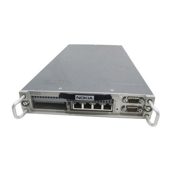
For more information and technical specifications, see “Technical Specifications” on page 87. Nokia IP200 Security Platform Appliance Overview The following figures show component locations for Nokia IP200 appliances. Figure 1 Component Locations Front View Status LEDs Auxiliary (AUX) port IP260 00024... -
Page 21: Built-In Ethernet Ports
Nokia products support NICs purchased from Nokia Corporation or Nokia-approved resellers only. The Nokia Global Support Services group can provide support only for Nokia products that use Nokia-approved accessories. For sales or reseller information, contact a Nokia service provider listed in the “Nokia Contact Information”... -
Page 22: Console And Serial (Aux) Ports
Caution Nokia recommends that you use the console cable that was delivered with your appliance for your console connection. Otherwise, ensure that the pin assignments for your cable match those provided in this section. -
Page 23: Figure 4 Pin Assignments For Console And Aux Connections
Figure 4 Pin Assignments for Console and AUX Connections Input or Pin# Assignment output Input (AUX port only; not used 00460 by the console port) Input Output Output Input Output Input not used Nokia IP200 Series Security Platform Installation Guide... -
Page 24: System Status Leds
8 (CTS) 7 (RTS) 4 (RTS) System Status LEDs You can monitor the basic operation of Nokia IP200 appliances by checking their status LEDs. The system status LEDs are located on the front panel of the appliance, as Figure 5 shows. -
Page 25: Table 4 Appliance Status Leds
LEDs for all indications they might display. Table 4 Appliance Status LEDs Indicator Color Description Caution None (off) Normal Yellow (steady) Initial boot flash activity Internal voltage problem Yellow (blinking) Temperature fault Nokia IP200 Series Security Platform Installation Guide... -
Page 26: Site Requirements
“Built-in Ethernet Ports” on page 21. Site Requirements Before you install a Nokia IP200 appliance, ensure that your computer room or wiring closet conforms to the environmental specifications listed in Appendix A, “Technical Specifications.” Product Disposal At the end of its useful life, your appliance and all peripherals included with it, including power cords and cables, must be disposed of in accordance with all applicable national, state, and local laws and regulations. -
Page 27: Safety Warnings And Cautions
Safety Warnings and Cautions Therefore, to help prevent damage to the environment, Nokia encourages you to dispose of these devices in an environmentally-friendly manner. The following resources are available to you to help with equipment-disposal decisions: Many Nokia products are labeled with information about the materials used in their manufacture that can help those who will process equipment after you have disposed of it. -
Page 28: Managing Ip200 Security Platform Appliances
HAR cordage and IEC fittings approved by the country of end use. Managing IP200 Security Platform Appliances You can manage Nokia IP200 appliances by using one of the following interfaces: Nokia Network Voyager—an SSL-secured, Web-based element management interface to Nokia IP security platforms. Network Voyager is preinstalled on the IP200 appliance and enabled through the IPSO operating system. - Page 29 Managing IP200 Security Platform Appliances For information about how to access the CLI, see the Nokia CLI Reference Guide for the version of IPSO you are using. Nokia Horizon Manager—a secure GUI-based software image management application. With Horizon Manager, you can securely install and upgrade the Nokia proprietary IPSO operating system, plus hardware and third-party applications such as Check Point FireWall-1.
- Page 30 Overview Nokia IP200 Series Security Platform Installation Guide...
-
Page 31: Installing A Nokia Ip200 Security Appliance
Installing a Nokia IP200 Security Appliance You can rack mount Nokia IP200 Security appliances in the following ways: A single appliance in a one-unit space (1U) Two appliances can be rack mounted in a 1U space if you install them in a rack-mountable shell, which you can order separately. -
Page 32: Figure 6 Installing The Mounting Brackets
Installing a Nokia IP200 Security Appliance Figure 6 Installing the Mounting Brackets Bracket position A Bracket position B 00423 You can mount IP200 appliances in a standard 19-inch rack with four mounting screws as Figure 7 shows. Nokia IP200 Series Security Platform Installation Guide... -
Page 33: Rack Mounting Two Nokia Ip200 Appliances Side By Side
00424 Rack Mounting Two Nokia IP200 Appliances Side by Side The following procedure describes how to install two Nokia IP200 appliances in a 1U rack space. This method does not allow you to change the position of the mounting brackets, as you can when you use the single-appliance installation method. - Page 34 1. Secure the rack-mountable shell on the rack with two screws on each side. Note To avoid damaging your equipment, Nokia recommends that you use all four rack-mounting screws when you install your appliance on the rack. Mounting Screws 00427 2.
- Page 35 Note Filler panels are shipped with the shell if you order it separately. If you do not have a filler panel available and need one, contact your Nokia sales representative. Filler panel...
- Page 36 To remove the appliance, use a screwdriver to turn the locking latch counterclockwise until you cannot turn it with light force. To secure the appliance To release the appliance 00426 Nokia IP200 Series Security Platform Installation Guide...
- Page 37 The following figure shows how the installation appears if you are using two appliances side-by-side in a 1U space. 00429 Nokia IP200 Series Security Platform Installation Guide...
- Page 38 Installing a Nokia IP200 Security Appliance Nokia IP200 Series Security Platform Installation Guide...
-
Page 39: Performing The Initial Configuration
Performing the Initial Configuration The first time you turn on power to a Nokia IP200 appliance, the initial configuration process begins. This process enables you to configure the network settings and provides access to the admin account. You can perform the initial configuration in two ways: Configure a DHCP server to provide the initial configuration information the first time the appliance is started. -
Page 40: Using A Console Connection
Chapter 6, “Installing Flash-Memory PC Cards.” Using a Console Connection If you do not use DHCP to perform the initial configuration of your Nokia IP200 appliance, you must use a serial console connection (cable included). After you perform the initial configuration, the console connection is no longer required. -
Page 41: Connecting Power And Turning The Power On
Connecting Power and Turning the Power On A power switch and a receptacle for the power cord are located on each power supply on the back of the appliance as shown in Figure Nokia IP200 Series Security Platform Installation Guide... -
Page 42: Figure 8 Power Switch Location
Note Because the flash-memory PC card is hot replaceable for the IP200, you do not need to install a flash-memory PC card to boot from before you turn on the appliance. Nokia IP200 Series Security Platform Installation Guide... -
Page 43: Performing The Initial Configuration
(115 VAC or 220 VAC [100 to 127 and 200 to 240]) and configures itself appropriately. 4. Check the power LED (the Nokia logo) on the front panel of the appliance to ensure that the power supply is operating correctly. - Page 44 If you verify the console connections and still do not see either the BOOTMGR> or Hostname? prompts, verify that the terminal or terminal emulator program settings are correct. If the settings are correct, contact your Nokia service provider as listed in “Nokia Contact Information”...
-
Page 45: Connecting Network Interfaces
Network Voyager to configure them. Connecting Network Interfaces Connect at least one network interface to the network to use as the Nokia Network Voyager system-management interface. You can also connect the remaining Ethernet interface cables at this point, although you are not required to do so. -
Page 46: Using Nokia Network Voyager To Manage Your Appliance
Performing the Initial Configuration how to use Network Voyager, the CLI, and Nokia Horizon Manager are provided in the following sections. Using Nokia Network Voyager to Manage Your Appliance You can use Nokia Network Voyager, an SSL-secured, Web-based element management interface to Nokia IP security platforms, to configure and monitor your appliance. -
Page 47: Viewing Nokia Ipso Documentation By Using Nokia Network Voyager
Using Nokia Network Voyager to Manage Your Appliance Viewing Nokia IPSO Documentation by Using Nokia Network Voyager Nokia Network As you use Voyager, the Nokia Network Voyager Reference Guide for the version of IPSO you are using and Network Voyager inline help (context-sensitive help) are available for you to use. -
Page 48: Using The Command-Line Interface To Manage Your Appliance
IPSO The Nokia Network Voyager Reference Guide is the comprehensive reference source for Nokia Network Voyager. To access this source if you are running Nokia IPSO, click Doc. You can also access the Nokia Network Voyager Reference Guide for IPSO... -
Page 49: Using Nokia Horizon Manager
For more information about how to access and use the CLI, see the Nokia CLI Reference Guide for the version of IPSO you are using. Using Nokia Horizon Manager You can use Nokia Horizon Manager to install and upgrade Nokia IPSO. For information about how to obtain Horizon Manager, see the “Nokia Contact... - Page 50 Performing the Initial Configuration Nokia IP200 Series Security Platform Installation Guide...
-
Page 51: Connecting To The Ethernet Ports
If you do not have a grounding wrist strap, make sure you are properly grounded before you touch any electronic component. Built-In Four-Port 10/100 Ethernet Interface Every Nokia IP200 appliance has four built-in dual-mode 10-Mbps and 100-Mbps ports. Nokia IP200 Series Security Platform Installation Guide... -
Page 52: Ethernet Features
“Using Nokia Network Voyager to Manage Your Appliance” on page 46. For information about how to access the CLI, see the Nokia CLI Reference Nokia Guide for the version of IPSO you are using. After the power is turned on, the Ethernet link LEDs on the appliance and on the remote equipment illuminate to indicate the connection. -
Page 53: Figure 10 Output Connector For The Ethernet Cable
The following figure shows the pin assignments for the cable. The RJ-45 cable output connector is numbered from left to right, with the copper tabs facing down and toward you. Figure 10 Output Connector for the Ethernet Cable Pin# Assignment 00270.1a Nokia IP200 Series Security Platform Installation Guide... -
Page 54: Figure 11 Ethernet Crossover Cable Pin Connections
Connecting to the Ethernet Ports The following figure shows the pin assignments for the RJ-45 crossover cable. Figure 11 Ethernet Crossover Cable Pin Connections 00017.1 Nokia IP200 Series Security Platform Installation Guide... -
Page 55: Configuring And Activating Encryption Acceleration
Perform the procedures in this section only if SecureXL is turned off. If SecureXL is turned on, the accelerator is automatically enabled. The accelerator card software package is part of Nokia IPSO, so the appliance automatically detects and configures the card. -
Page 56: Configuring Software To Use Hardware Acceleration
Acceleration Nokia Network Voyager to configure virtual private network (VPN) tunnels to use hardware acceleration. This step is necessary to use Nokia encryption acceleration on IP200 appliances. To enable encryption acceleration for a Check Point VPN 1. Access Nokia Network Voyager. -
Page 57: Installing Flash-Memory Pc Cards
IP200 appliance to provide non-volatile, random-access memory (RAM). You can use the flash-memory PC card to store local system logs, Nokia IPSO images, and configuration files. The IP200 appliance has two PC-card slots that each support an 8-MB or greater flash-memory PC card. -
Page 58: Before You Begin
00425 Before You Begin To install a flash-memory PC card, you need: Physical access to the appliance Access to the appliance by using Nokia Network Voyager or the command-line interface (CLI) Replacement flash-memory PC card and accompanying documentation Caution To avoid potential equipment malfunction, Nokia recommends that you obtain flash-memory PC cards only from Nokia or authorized resellers. -
Page 59: Installing A Flash-Memory Pc Card
PC card. Note You can use only one of the slots at a time, and Nokia recommends that you use only the top PC-card slot for optimum ESD protection. To install the flash-memory PC card 1. - Page 60 Installing Flash-Memory PC Cards To use Nokia Network Voyager to disable a flash-memory PC card you use for storing system logs before you remove it Click System Logging under System Configuration and check the Unselect check box. 2. Click Apply.
-
Page 61: Transferring Files With The Flash-Memory Pc Card
Transferring Files with the Flash-Memory PC Card You can copy Nokia IPSO images or configuration files between the internal compact flash memory and the flash-memory PC card. If you do not use Nokia Network Voyager to configure the flash-memory PC card as an... - Page 62 6. To remove the card, slowly push the eject button located to the left of the card. Caution Hold the flash-memory PC card while you push the eject button to prevent the card from ejecting too quickly. Nokia IP200 Series Security Platform Installation Guide...
-
Page 63: Using The Nokia Ipso Boot Manager
Installing new versions of Nokia IPSO (the operating system). For information on installing new version of Nokia IPSO images, see the Getting Started Guide and Release Notes for the version of IPSO that you are using. - Page 64 Unless you set the autoboot variable to no, the appliance automatically boots Nokia IPSO after waiting at the boot manager prompt for the number of seconds specified by the bootwait variable. For further information, see “Setting and Viewing Boot-Manager Variables”...
-
Page 65: Starting The Boot-Manager Command-Line Interface
If you do not press a key, the system continues to boot after the bootwait period expires. The boot manager command prompt appears: BOOTMGR[1]> 5. To exit the boot manager and continue booting up, type boot Nokia IP200 Series Security Platform Installation Guide... -
Page 66: Stopping The System From The Boot Manager
Using the Boot Manager to Boot the System Use can use the boot command to boot up the Nokia IPSO operating system. The command also allows you to specify the boot device, boot file, and any number of boot flags from the command line. -
Page 67: Setting And Viewing Boot-Manager Variables
Table 5 lists the boot-manager variables that you can set. Note Nokia recommends that you do not modify any of the default values for boot manager variables. Table 5 Boot Manager Variables Variable Description... -
Page 68: Table 6 Boot Flags
Exit single-user mode by pressing Control + D, or by pressing Enter, after which the system restarts. Verbose mode. Verbose during device probing and thereafter. Instructs the system not to identify the flash disk as wd0. Rarely used. Nokia IP200 Series Security Platform Installation Guide... - Page 69 This example command sets the value of autoboot to YES: BOOTMGR[2]> setenv autoboot YES unsetenv Use the unsetenv command to set a variable to null value. The command has the following syntax: unsetenv name Nokia IP200 Series Security Platform Installation Guide...
- Page 70 Use the unsetalias command to clear an alias. The command has the following syntax: unsetalias name where name is the name of the alias to be cleared. For example, the following command deletes the flash alias from the list of aliases: BOOTMGR[2]> unsetalias flash Nokia IP200 Series Security Platform Installation Guide...
-
Page 71: Viewing Other System Information
.description bootmgr ipso.tgz rfs_utils RFS_LINKS cdrom kernel sbin VERSION kernel.debug sysinfo Use the sysinfo command to view system information such as CPU speed and memory size. The command has the following syntax: sysinfo Nokia IP200 Series Security Platform Installation Guide... -
Page 72: Protecting The Boot Manager With A Password
BOOTMGR[3]> Protecting the Boot Manager with a Password To prevent accidental or unauthorized access to the information stored on your appliance, you can require that the user enter a password to access the Nokia IP200 Series Security Platform Installation Guide... - Page 73 The boot manager password gives access to the install command in boot manager, it does not give access to Nokia IPSO. To set or change the boot manager password 1. At the boot manager command prompt enter: BOOTMGR[0]>...
- Page 74 5. At the boot manager command prompt, type passwd. The New Password prompt appears. 6. Enter your new password. 7. Turn off the power to the appliance. 8. Reinstall the hard-disk drive. 9. Turn on the power to the appliance. Nokia IP200 Series Security Platform Installation Guide...
-
Page 75: Resetting The Admin Password
Resetting the Admin Password Note If your system is flash-based (diskless) and you have lost both the admin and boot manager passwords, contact Nokia Customer Support for further assistance. See “Nokia Contact Information” on page 3 for contact details Resetting the Admin Password... -
Page 76: Reinstalling Or Upgrading The Boot Manager
This command does not appear in the CLI help menu. Reinstalling or Upgrading the Boot Manager When you add a Nokia IPSO image, the Nokia IPSO boot manager is upgraded automatically if your system does not have the boot manager for the image you are adding. - Page 77 To install, upgrade, or downgrade the boot manager 1. Obtain the boot manager you want to install. If you have access to the Nokia support web site, you can download the boot manager from the same page you would use to download Nokia IPSO system software.
-
Page 78: Troubleshooting
IP bmslice: 4 No referenced boot-file or boot-device appears. Setting the boot manager to defaults causes the boot manager to determine that no environment variables are set, and it responds by importing the Nokia IP200 Series Security Platform Installation Guide... - Page 79 BOOTMGR[93]> printenv NOKIA IPSO BOOTMGR VERSION=3.8 09.05.2003-130000 autoboot: YES testboot: NO bootwait: 3 boot-file: /image/current/kernel boot-flags: boot-device: wd0 vendor: Nokia model: IP bmslice: 4 Issue the halt command to restart your appliance: BOOTMGR> halt Nokia IP200 Series Security Platform Installation Guide...
- Page 80 Using the Nokia IPSO Boot Manager Nokia IP200 Series Security Platform Installation Guide...
-
Page 81: Troubleshooting
Troubleshooting This chapter provides troubleshooting tips, problems, and solutions related to Nokia IP200 appliance installations. For information about how to reinstall Nokia IPSO on to your appliance, see Chapter 7, “Using the Nokia IPSO Boot Manager.” General Troubleshooting Information The information in this section relates to problems you might encounter during the Nokia IP200 appliance installation. - Page 82 Information” on page 3. Login Prompt Appears, But Password Not Accepted Problem Database is corrupt Solution Return to default settings or contact the Nokia customer support site listed in “Nokia Contact Information” on page 3. Nokia IP200 Series Security Platform Installation Guide...
- Page 83 For information about how to complete the full installation procedure, see the current release notes. The release notes are located on the Nokia customer support Web site as listed in the “Nokia Contact Information”...
- Page 84 Troubleshooting Not Able to Connect to Nokia Network Voyager Using the Ethernet Port, But Console Access Works Problem Network Voyager access or Ethernet port disabled. Solution Use the CLI over the console connection to verify the interface configuration and modify the configuration as necessary. For more information, see the CLI Reference Guide for the version of IPSO you are using.
- Page 85 Solution Verify from the Interface page in Network Voyager that the interface port is configured as active. Problem High collision rate on the hub. Solution Disconnect connections one at a time until the problem is localized to one computer and troubleshoot further. Nokia IP200 Series Security Platform Installation Guide...
- Page 86 Troubleshooting Nokia IP200 Series Security Platform Installation Guide...
-
Page 87: A Technical Specifications
• 23.6 lbs. (10.7 kg): Shell containing two base systems Space Requirements Nokia IP200 appliances are designed for front-screw mounting in a 19-inch rack. Each IP200 appliance requires the following space in a rack: 1.60 inches (4.06 centimeters) of vertical space for a single appliance 1.71 inches (4.34 centimeters) of vertical space for appliances in a shell... -
Page 88: Other Specifications
The appliance might overheat and become damaged. For information about changes to the software requirements or additional applications that have become available since this guide was published, contact your Nokia service provider, as listed in “Nokia Contact Information” on page 3. -
Page 89: Appliance Interfaces
Appliance Interfaces Appliance Interfaces Interface Cable Type Cable Output Connector Ethernet IEEE 802.3 10BASE-T, 100BASE-TX unshielded RJ-45 twisted pair, full-duplex or half-duplex Nokia IP200 Series Security Platform Installation Guide... - Page 90 Technical Specifications Nokia IP200 Series Security Platform Installation Guide...
-
Page 91: B Compliance Information
This appendix contains the following compliance information: Declaration of Conformity Compliance Statements FCC Notice (US) Declaration of Conformity According to ISO/IEC Guide 22 and EN 45014: Manufacturer’s Name: Nokia Inc. Manufacturer’s Address: 313 Fairchild Drive Mountain View, CA 94043-2215 Nokia IP200 Series Security Platform Installation Guide... - Page 92 EMC: EN55024 1998, EN55022A 1998, EN61000-3-2, EN61000-3-3 Supplementary information: Pursuant to directive 1999/5/EC this product complies with the requirements of the Low Voltage Directive 73/23/EEC and the EMC Directive 89/336/EEC with Amendment 93/68/EEC. Nokia IP200 Series Security Platform Installation Guide...
-
Page 93: Compliance Statements
Mountain View, CA Compliance Statements This hardware complies with the standards listed in this section. Emissions Standards FCC Part 15 Subpart B Class A US/Canada EN55022 (CISPR 22 Class A) European Community (CE) Nokia IP200 Series Security Platform Installation Guide... -
Page 94: Fcc Notice (Us)
This device generates, uses, and can radiate radio frequency energy and, if not installed and used in accordance with the instruction, may cause harmful interference to radio communications. However, there is no Nokia IP200 Series Security Platform Installation Guide... - Page 95 Consult the dealer or an experienced radio/TV technician for help. Caution Any changes or modifications not expressly approved by the grantee of this device could void the user’s authority to operate the equipment. 050316 Nokia IP200 Series Security Platform Installation Guide...
- Page 96 Compliance Information Nokia IP200 Series Security Platform Installation Guide...
-
Page 97: Index
Ethernet net- cables work interfaces 53 console 40 console commands cable 40 boot 66 console cable connection 40 halt 76 help 76 ls 71 data communications equipment device 41 passwd 73 Nokia IP200 Series Security Platform Installation Guide Index - 97... - Page 98 76 Ethernet crossover-cable 54 interfaces pin connections for Ethernet crossover connecting network 45 cables 54 IP200 appliances power connections 41 monitoring 24 printenv command 69 ls command 71 Index - 98 Nokia IP200 Series Security Platform Installation Guide...
- Page 99 65 sysinfo command 71 technical specifications See specifications testboot 68 troubleshooting 78, 81 unsetalias command 70 unsetenv command 69 variables autoboot 67 boot flags 67 boot-device 67 boot-file 67 Nokia IP200 Series Security Platform Installation Guide Index - 99...
- Page 100 Index - 100 Nokia IP200 Series Security Platform Installation Guide...