Table of Contents
Advertisement
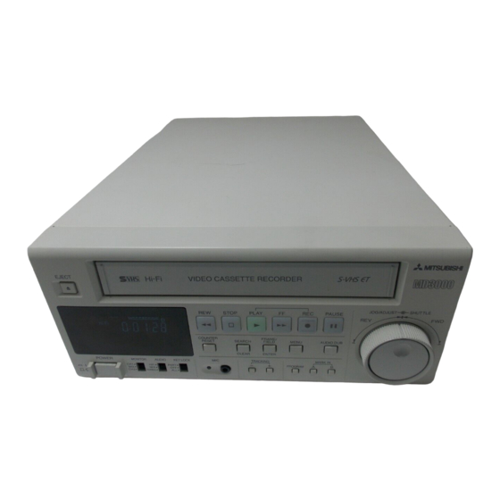
VIDEO CASSETTE RECORDER
MODEL
HS-MD3000E
INSTALLATION AND OPERATION MANUAL
625
Only video cassette tapes with the
The included power cord is used for 220 - 230 V, 50 Hz. Do not connect any outlet or
power supply having a different voltage or frequency.
This instruction manual is important to you.
Please read it before using your video cassette recorder.
This video cassette recorder complies with the requirements of the EC Directive 89/336/EEC,
93/42/EEC and 93/68/EEC.
The electro-magnetic susceptibility has been chosen at a level that gains proper operation in
residential areas, on business and light industrial premises and on small-scale enterprises,
inside as well as outside of the buildings. All places of operation are characterised by their
connection to the public low voltage power supply system.
VHS
PAL
mark or the
mark may be used with this model.
Advertisement
Table of Contents

Related Manuals for Mitsubishi Electric HS-MD3000E


Summary of Contents for Mitsubishi Electric HS-MD3000E
- Page 1 VIDEO CASSETTE RECORDER MODEL HS-MD3000E INSTALLATION AND OPERATION MANUAL Only video cassette tapes with the mark or the mark may be used with this model. The included power cord is used for 220 - 230 V, 50 Hz. Do not connect any outlet or power supply having a different voltage or frequency.
- Page 2 “CLASSIFIED BY UNDERWRITERS LABORATORIES INC.® WITH RESPECT TO ELECTRIC SHOCK, FIRE AND MECHANICAL HAZARDS ONLY IN ACCORDANCE WITH UL 2601-1 AND CAN/CSA C22.2 NO. 601.1.” According to Clause 5 in UL 2601-1 sec 6.8.1 or EN60601-1 sec 6.8.1, this unit is classified by the following;...
-
Page 3: Safety Precautions
Safety Precautions TECHNICAL DESCRIPTIONS The supplier will make available on request such circuit diagrams, component part lists, descriptions, calibration instructions or other information which will assist the USER’s appropriately qualified technical personnel to repair those parts of the EQUIPMENT which are classified by the manufacturer as repairable. -
Page 4: Caution And Care
Caution and Care CONDENSATION IS THE ENEMY OF VIDEO RECORDERS What is condensation? 1. When a very cold drink is poured into a glass, the water droplets which form on the outer surface of the glass are an example of condensation. -
Page 5: Table Of Contents
Features S-VHS Mode Easy Menu Setting on Screen with Multi Languages Hi-Fi Audio Recording All or Part Front Panel Lock Digital Frame/Field Still Picture Versatile Searching Function Blank Search Digital Noise Reduction Index Search Digital Y/C Separation Time Date Search Digital Time Base Corrector Audio Dubbing Swift and Reliable Mechanism... -
Page 6: Controls And Functions
Controls and Functions Front View EJECT JOG/ADJUST SHUTTLE STOP PLAY PAUSE COUNTER FRAME/ RESET SEARCH FIELD MENU AUDIO DUB CLEAR ENTER POWER MONITOR AUDIO KEY LOCK TRACKING MARK IN – PROGRAM HiFi PART NORMAL Symbol " ": on (power connection to the mains) Symbol "... - Page 7 SEARCH/CLEAR button Press to display the <SEARCH FUNCTION> menu. When setting the current time on MENU 3, use to select the setting item in the upward direction. TRACKING buttons Press to reduce/eliminate the noise during playback. FRAME/FIELD/ENTER button During playback, still picture or playback using the shuttle ring, press to display the freeze frame picture.
-
Page 8: Fluorescent Display
Controls and Functions (Cont.) Fluorescent Display (S-VHS) indicator (Audio Dubbing) indicator Illuminates during playback a tape recorded in S-VHS mode. Illuminates during audio dubbing. Also illuminates when “S-VHS” in “MENU 2” is set to “AUTO” (Index Search) indicator and a S-VHS tape or no tape is loaded. Flashes when recording an index signal and illuminates during (MENU) indicator the index number setup and the index search. -
Page 9: Rear View
Rear View AUDIO VIDEO S-VIDEO 75ohm 75ohm OFF ON OFF ON AUDIO LOOP THROUGH MONITOR RESET FOOT REMOTE Symbol " ": equipotentiality Symbol " ": alternating current Warning: The included power cord is used for 220 - 230 V, 50 Hz. Do not connect to any outlet or power supply having a different voltage or frequency. -
Page 10: Basic Functions
Loading/Unloading a Tape Manual Recording Tapes can be loaded into your VCR as long as the VCR is plugged 1. Turn on the VCR and peripheral into an outlet and turned on. Use only video cassette tapes marked devices. Important notice: 2. -
Page 11: Playback
Audio recording/playback Rewinding a tape When an AUDIO IN (CH-1/L) or AUDIO IN (CH-2/R) is connected, Press REW button. the normal audio signal is recorded on the linear track. Set To stop rewinding, press STOP button. NORMAL AUDIO IN in MENU 2 for selecting the audio signal to be recorded. -
Page 12: Advanced Functions
Programmed Playback Audio Dubbing This function allows you to repeatedly playback the desired This function allows you to record the audio signal from microphone portion of the tape which is marked with MARK IN A/B onto an already recorded tape. When the microphone is not buttons on the front panel. -
Page 13: Additional Features
Field playback Additional Features 1. To forward fields one by one, turn JOG during still picture. Memory backup in case of power failure • Turn to the right to forward. • Turn to the left to reverse. This VCR includes a built-in backup memory, so the preset day and present time and the counter display will remain in memory even if To forward fields continuously, keep turning JOG during still there is a power failure. -
Page 14: Searching Techniques
1. Press SEARCH button several times. Searching Techniques <SEARCH FUNCTION> BLANK SEARCH • SKIP SEARCH is highlighted. COUNTER MEMORY STOP SKIP SEARCH INDEX SEARCH The various search function helps you to find a picture you wish to TIME DATE SEARCH 2. -
Page 15: Time Date Search
Time date search You can easily find a picture recorded at specific date and time. 1. Press SEARCH button several times. <SEARCH FUNCTION> BLANK SEARCH COUNTER MEMORY STOP • TIME DATE SEARCH SKIP SEARCH highlighted. INDEX SEARCH TIME DATE SEARCH 2. -
Page 16: Installation
Connections Connecting with ultrasonic inspecting instrument, video monitor, etc Video input (S-video connector) Video input Ultrasonic inspecting (BNC-type connector) instrument, etc Audio input Video output Video output Audio output (S-video connector) (BNC-type connector) AUDIO VIDEO S-VIDEO 75ohm 75ohm OFF ON OFF ON AUDIO LOOP... -
Page 17: Clock Setting
Setting the current time to exact second Clock Setting Set the clock as described to the left, but set minute digits to Example : Setting the day and present time to 8:25 p.m., 9 July, one or two minutes ahead of the reference time being used. 2002. -
Page 18: Menu Settings
Menu Settings Menu Chart Press the MENU button <MENU 1> <MENU 2> <ELAPSED TIME> <MENU 3> REC TAPE END STOP S-VHS AUTO HEADS DAYLIGHT SAVINGS AUTO TAPE END STOP Y-NR POWER MONTH TAPE IN STOP C-NR TAPE LENGTH E-180 Y-ENHANCER YEAR 2002 VISS... -
Page 19: Language Selection
LANGUAGE SELECTION Displaying the time code (TIME DATE DISP.) : The time code is not displayed. The menu which appears on screen offers 7 languages. This menu appears by pressing MENU button, when the VCR is : The time code is displayed on the top of the screen. -
Page 20: Elapsed Time
MENU 2 S-VHS 201:00 Menu Settings (Cont.) AUTO 201:01 Setting the audio signal recorded on the linear track Y-NR 202:00 (NORMAL AUDIO IN) 202:01 : The audio signal from CH1 and CH2 are mixed and C-NR 203:00 recorded. 203:01 : The audio signal input from CH1 terminal is recorded. : The audio signal input from CH2 terminal is recorded. -
Page 21: Others
Before Calling for Service When you find any problem with this VCR, first check the following. If you still cannot solve the problem, stop using the VCR, unplug it from an outlet and contact your dealer. Symptom Check list/Remedy Installation No power supplied to VCR. -
Page 22: Warning Display
Warning Display Self-diagnostic function This VCR uses a self-diagnostic function to detect an internal malfunction. When a malfunction occurs in the VCR, the indication corresponding to each malfunction illuminates on the fluorescent display. The type of malfunction corresponding to the indication and countermeasures are given below. If the error is not cleared even after taking the remedial action described below, switch off the power, disconnect the power cable from the power outlet, and contact your dealer immediately. -
Page 23: Maintenance
Maintenance RECOMMEMDED TIME OF REPLACEMENT SPECIFICATION EVERY 1,000 HOURS UPPER DRUM ASSY EVERY 4,000 HOURS CAPSTAN MOTOR, CAPSTAN BRAKE UNIT, IDLER UNIT, REEL DISK, ASSY GEAR PULLEY, BRAKE BELT (SP, TU), CLEANING ROLLER EVERY 4,000 HOURS OR 3 YEARS PINCH ARM UNIT, REEL BELT EVERY 10,000 HOURS ASSY DRUM, A/C HEAD UNIT, LOADING MOTOR ASSY, FE HEAD 5 YEARS AFTER MANUFACTURING... - Page 24 MITSUBISHI DIGITAL ELECTRONICS AMERICA, INC. 9351 Jeronimo Road, Irvine, CA 92618, U.S.A. Phone 949-465-6000 www.mitsubishi-imaging.com Tech Support 888-307-0309 tsupport@mdea.mea.com Mitsubishi Electric Europe B.V. UK Branch Travellers Lane, Hatfield, Herts. AL10 8XB, England, U.K. Phone (0) 1707 276100 FAX (0) 1707 278755 German Branch Gothaer Strasse 8, 40880 Ratingen ;...