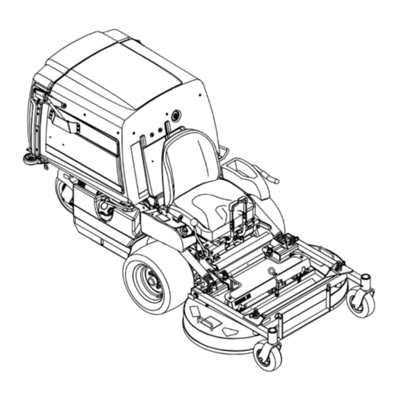
Toro 74312 Operator's Manual
Riding mower with 48in cutting unit
Hide thumbs
Also See for 74312:
- Operator's manual (64 pages) ,
- Setup instructions (12 pages) ,
- Setup instructions (12 pages)
Table of Contents

Related Manuals for Toro 74312


Summary of Contents for Toro 74312
- Page 1 Form No. 3414-678 Rev A Z Master ® 8000 Series Riding Mower with 48in Cutting Unit Model No. 74312—Serial No. 400000000 and Up Model No. 74313—Serial No. 400000000 and Up *3414-678* A Register at www.Toro.com. Original Instructions (EN)
- Page 2 Whenever you need service, genuine Toro parts, or additional information, contact an Authorized Service Dealer or Toro Customer Service and have the model and serial numbers of your product ready. Figure 1 identifies the location of the model and serial numbers on the product.
-
Page 3: Table Of Contents
Contents Servicing the Fuel Tank........39 Electrical System Maintenance ......39 Electrical System Safety ........39 Safety ............... 4 Servicing the Battery......... 39 General Safety ........... 4 Servicing the Fuses .......... 41 Slope Indicator ........... 5 Adjusting the Safety Switches......41 Safety and Instructional Decals ...... -
Page 4: Safety
Safety This machine has been designed in accordance to the ANSI B71.4–2012 specification of the American National Standards Institute with the addition of the optional ROPS accessory. General Safety This product is capable of amputating hands and feet and of throwing objects. Always follow all safety instructions to avoid serious personal injury. -
Page 5: Slope Indicator
Slope Indicator G011841 g011841 Figure 3 This page may be copied for personal use. 1. The maximum slope you can safely operate the machine on is 15 degrees. Use the slope chart to determine the degree of slope of hills before operating. Do not operate this machine on a slope greater than 15 degrees. Fold along the appropriate line to match the recommended slope. -
Page 6: Safety And Instructional Decals
Safety and Instructional Decals Safety decals and instructions are easily visible to the operator and are located near any area of potential danger. Replace any decal that is damaged or missing. decal93-6696 93-6696 1. Stored energy hazard—read the Operator's Manual. decal112-8760 112-8760 1. - Page 7 decal116-8936 116-8936 1. Danger—do not operate with deck in tilt-up position. decal116-8813 116-8813 1. Hopper up indicator 5. Parking brake 2. Battery 6. Neutral 3. Hour meter 7. Operator presence switch 4. PTO decal116-8941 116-8941 decal116-8934 decal116-8943 116-8934 116-8943 1. Warning—disengage 2.
- Page 8 decal116-8946 116-8946 1. Rotate counterclockwise 3. Unlock to push the to release machine 2. Rotate clockwise to lock 4. Read the instructions before servicing or performing maintenance. decal116-9044 116-9044 1. Read the Operator’s Manual before performing any 8. Grease the deck-lock mechanism every 100 hours. maintenance.
- Page 9 decal116-9049 116-9049 decal126-4207 1. Rotating driveline hazard—keep all driveline shields in 126-4207 place. Securely attach both ends of the driveline. 1. Refer to the Operator’s Manual for adjustment procedure. When the PTO is engaged, idler arm position must be in hatched area;...
- Page 10 decal126-4158 Molded into Front of Hopper 1. Warning—Read the Operator’s Manual. Do not operate this 5. Warning—Stay away from moving parts; keep all guards machine unless you are trained. Wear hearing protection. in place. Shut off the engine and remove the key before adjusting, servicing, or cleaning.
- Page 11 decalbatterysymbols Battery Symbols Some or all of these symbols are on your battery 1. Explosion hazard 6. Keep bystanders a safe distance away from the battery. 2. No fire, open flame, or 7. Wear eye protection; explosive gases can smoking cause blindness and other injuries 3.
- Page 12 decal130-2881 130-2881 1. Engine temperature 7. Retract the piston 2. Fast 8. Extend the piston 3. Slow 9. Fast 4. Neutral 10. Slow 5. Neutral 11. MIL toggle switch 6. Reverse...
-
Page 13: Product Overview
Ignition Switch Product Overview Use this switch to start the mower engine. It has 3 positions: S , and O TART Choke Control (Not on EFI machines) Use the choke to start a cold engine. Move the choke to the C position to start a cold engine. - Page 14 Contact your Battery-Indicator Light Authorized Service Dealer or Distributor or go to www.Toro.com for a list of all approved attachments If you turn the ignition key to the O position for a and accessories.
-
Page 15: Specifications
Specifications Operation Note: Specifications and design are subject to Note: Determine the left and right sides of the change without notice. machine from the normal operating position. Width Before Operation 42-inch Mower 48-inch Mower Deck Deck Without Mower 108.2 cm (42.6 108.2 cm (42.6 Before Operation Safety Deck... -
Page 16: Recommended Fuel
Using containers on the ground, away from your vehicle before filling. Stabilizer/Conditioner • Remove the equipment from the truck or trailer and refuel it while it is on the ground. If this is not Use a fuel stabilizer/conditioner in the machine to possible, then refuel from a portable container provide the following benefits: rather than a fuel-dispenser nozzle. -
Page 17: Think Safety First
Think Safety First Use protective equipment for your eyes, ears, hands, feet, and head. Please read all safety instructions and symbols in the safety section. Knowing this information could help you or bystanders avoid injury. DANGER Operating the machine on wet grass or steep G009027 slopes can cause sliding and loss of control. -
Page 18: Lowering The Mower Deck To The Operating Position
Lowering the Mower Deck to the Operating Position 1. While firmly holding onto deck-lift handle, unhook the mower-deck latch from the machine and slowly lower the mower deck to the ground (Figure 10). 2. Push the deck-locking pins inward and rotate them forward to securely lock the mower deck in the lowered position (Figure... -
Page 19: The Safety-Interlock System
g006787 Figure 11 1. Hairpin cotter and clevis pin 5. Loosen the locknuts on the rear studs of the FRS baffles. g007577 Figure 13 1. Baffles—closed position 2. Baffles—open position 3. Bolt 4. Washer 5. Baffles 9. Lower the mower deck; refer to Lowering the Mower Deck to the Operating Position (page 18). -
Page 20: During Operation
Understanding the 3. Sit on the seat, disengage the parking brake, move the PTO-engagement lever to the O Safety-Interlock System position, and move the speed-control lever to the N position. Try starting the engine; The safety-interlock system is designed to prevent the EUTRAL the engine should not start. -
Page 21: Operating The Throttle
15 seconds between • Use accessories and attachments approved by attempts. Failure to follow these instructions Toro only. can burn out the starter motor. Note: You may need multiple attempts to start Slope Safety the engine when you start it the first time after •... -
Page 22: Operating The Pto-Engagement Lever
Operating the Disengaging the PTO-Engagement Lever PTO-Engagement Lever The PTO-engagement lever starts and stops the mower blades and blower. WARNING An uncovered discharge opening allows objects to be thrown at you and bystanders. Also, contact with the blower blades could occur. -
Page 23: Starting And Shutting Off The Engine
Disengaging the Parking Brake g032727 Figure 20 Starting and Shutting Off the Engine Starting the Engine 1. Move the speed-control lever to the N EUTRAL position. 2. Engage the parking brake; refer to Engaging the Parking Brake (page 22). 3. Move the PTO-engagement lever to the O position (Figure 21). -
Page 24: Driving Forward Or Backward
Shutting Off the Engine CAUTION Children or bystanders may be injured if they move or attempt to operate the machine while it is unattended. Always remove the ignition key and engage the parking brake when leaving the machine unattended, even if just for a few minutes. Important: Make sure that the fuel-shutoff valve is closed before transporting or storing the... -
Page 25: Adjusting The Height Of Cut
Driving Forward Note: To begin movement (forward or backward), , sit in the seat, disengage (push down) the brake lever, then move the speed-control lever forward; otherwise, the engine will stop. To stop the machine, pull the speed control lever to the N position. -
Page 26: Operating Tips
It is best to cut only about a third of the grass blade. genuine Toro replacement blade. Cutting more than that is not recommended unless grass is sparse, or it is late fall when grass grows After Operation more slowly. -
Page 27: Clearing The Hopper Screen
Clearing the Hopper Screen 1. Move the speed-control lever to the N EUTRAL position to stop the machine. Remove the screen by firmly lifting the screen handles 2. Disengage the PTO lever, engage the parking (Figure 24). brake, shut off the engine, and wait for all moving parts to stop. -
Page 28: Loading The Machine
Loading the Machine Use extreme caution when loading or the unloading machine onto a trailer or a truck. Use a full-width ramp that is wider than the machine for this procedure. Important: If a full-width ramp is not available, use enough individual ramps to simulate a full-width ramp. -
Page 29: Maintenance
• Adjust the caster-pivot bearings. • Check the parking brake adjustment. • Change the hydraulic filter and reservoir hydraulic fluid when using Toro® HYPR-OIL™ 500 hydraulic fluid (more often in dirty or dusty conditions). • Change the oil in all 3 gearbox housings and add oil as needed. -
Page 30: Pre-Maintenance Procedures
– Disconnect the spark-plug wire. safety certification of the machine, use only • Park the machine on a level surface. genuine Toro replacement parts and accessories. • Clean grass and debris from the cutting unit, Replacement parts and accessories made by drives, mufflers, and engine to help prevent fires. -
Page 31: Lubrication
Lubrication Lubricating the Machine Service Interval: Before each use or daily—Grease the front caster wheel hubs (more often in dirty or dusty conditions). Every 40 hours—Grease the drive shaft (more often in dirty or dusty conditions). Every 100 hours—Grease the mower-deck flip-up pivot (more often in dirty or dusty conditions). - Page 32 Lubricating the Caster-Wheel 12. Insert the second bearing and new seal into the wheel. Hubs 13. Apply a thread-locking compound to the second Service Interval: Yearly spacer nut and thread it onto the axle with the wrench flats facing outward. 1.
- Page 33 Lubricating the Brake-Rod 5. Remove the small magnetic plugs and wipe away any material accumulated on the plugs. Bushings and Steering-Linkage 6. Apply a Teflon ® pipe sealant to all small magnetic Rod Ends plugs and install them into the gearbox. Service Interval: Every 160 hours 7.
-
Page 34: Engine Maintenance
Engine Maintenance WARNING Contact with hot surfaces may cause personal injury. Keep your hands, feet, face, clothing, and other body parts away the muffler and other hot surfaces. Engine Safety g032301 Figure 29 Shut off the engine before checking the oil or adding 1. -
Page 35: Servicing The Engine Oil
Installing the Filters Checking the Engine-Oil Level Important: To prevent engine damage, always Service Interval: Before each use or daily operate the engine with both air filters and the Note: Check the oil when the engine is cold. cover installed. Important: Do not overfill the crankcase with oil 1. - Page 36 Changing the Engine Oil Changing the Engine-Oil Filter Service Interval: Every 200 hours Service Interval: Every 100 hours (more often in dirty or dusty conditions). Note: Change the engine-oil filter more frequently when operating conditions are extremely dusty or Note: Dispose of the used oil at a recycling center.
-
Page 37: Servicing The Spark Plugs
Servicing the Spark Plugs Checking the Spark Plugs Important: Replace the spark plugs when they Service Interval: Every 200 hours—Check and gap have: a black coating, worn electrodes, an oily the spark plug (EFI engines only). film, cracks or reuse is questionable. Every 500 hours—Check and gap the spark If you see light brown or gray on the insulator, the plug (Non-EFI engines only). -
Page 38: Checking The Spark Arrester
Checking the Spark Fuel System Arrester Maintenance For a Model with a Spark Arrester WARNING Service Interval: Every 50 hours Fuel system components are under high pressure. The use of improper components WARNING can result in system failure, fuel leakage, and possible explosion. -
Page 39: Servicing The Fuel Tank
Electrical System Maintenance Electrical System Safety • Disconnect the battery before repairing the machine. Disconnect the negative terminal first and the positive last. Connect the positive terminal first and the negative last. • Charge the battery in an open, well-ventilated area, away from sparks and flames. - Page 40 Removing the Battery WARNING Battery terminals or metal tools could short against metal machine components causing sparks. Sparks can cause the battery gases to explode, resulting in personal injury. • When removing or installing the battery, do not allow the battery terminals to touch any metal parts of the machine.
-
Page 41: Servicing The Fuses
Adjusting the Safety 3. Install the battery in the machine and connect the battery cables, refer to Installing the Battery Switches (page 40). Note: Do not run the machine with the battery Adjust all safety switches so that the plunger extends disconnected;... - Page 42 systems. Make sure that the cables are color 5. Connect the black negative (–) cable to the other coded or labeled for the correct polarity. terminal (negative) of the booster battery. 6. Make the final connection on the engine block CAUTION of the stalled vehicle (not to the negative battery post) away from the battery and stand back.
-
Page 43: Drive System Maintenance
Drive System Note: The front tires are semi-pneumatic tires and does not require air pressure maintenance. Maintenance Adjusting the Tracking Note: The tracking knob is located under the seat. Note: Rotating this knob allows fine tuning adjustments so that the machine tracks straight with the drive levers in the full forward position. -
Page 44: Cooling System Maintenance
Cooling System 4. Tighten the locknut until the spring washers are flat and then back off 1/4 turn to properly set the Maintenance pre-load on the bearings (Figure 44 Figure 45). Important: Make sure that the spring Cleaning the Engine Screen washers are installed correctly as shown in Figure 44 Figure... -
Page 45: Checking And Cleaning The Hydraulic Pumps
Checking and Cleaning the Brake Maintenance Hydraulic Pumps Adjusting the Parking Service Interval: Before each use or daily Brake 1. Move the speed-control lever to the N EUTRAL position to stop the machine. Service Interval: After the first 100 hours 2. - Page 46 g020525 Figure 48 1. 22.7 to 23.3 cm (8.92 to 2. Nuts 9.16 inches) 9. Engage and disengage the brakes to check for proper engagement and disengagement. Adjust g020489 Figure 47 if necessary. 1. Parking brake 4. Vertical spring assembly Note: When the brakes are disengaged, there 2.
-
Page 47: Belt Maintenance
Belt Maintenance 10. Rotate the brake band down into the original position. 11. Install the clevis pin and hairpin cotter to secure Inspecting the Belts the brake band. 12. Engage the PTO lever. Service Interval: Every 40 hours 13. Loosen the jam nuts and adjust the linkage until 1. -
Page 48: Replacing The Pump-Drive Belt
Replacing the Pump-Drive Adjusting the Belt Guides Belt 1. Stop the machine and move the speed-control lever to the N position. EUTRAL 1. Stop the machine and move the speed-control 2. Disengage the PTO, engage the parking brake, lever to the N position. -
Page 49: Controls System Maintenance
Controls System F. Repeat steps through until you achieve up to 3 mm (1/8 inch) Maintenance movement. G. Install the seat frame assembly, if removed in step A. Adjusting the Reverse-Stop Adjusting the 1. Stop the machine and move the speed-control Speed-Control Lever lever to the N position. -
Page 50: Adjusting The Speed-Control Linkage
Adjusting the 11. Adjust the right pump linkage by using a wrench to turn the double nuts on the assembly (Figure Speed-Control Linkage WARNING The engine must be running and the drive wheels must be turning to adjust the motion controls. -
Page 51: Aligning The Pump-Drive Pulley
3. Remove the fuel-tank mounting nuts and swing 1. Shut off the machine and move the speed-control out the fuel tank. lever to the N position. EUTRAL 4. Verify that the blower is installed and tightly 2. Disengage the PTO, engage the parking brake, secured. -
Page 52: Adjusting The Hopper Door
Adjusting the Hopper Door Adjusting the Locking-Pin Stop on the Mower Deck 1. Stop the machine and move the speed-control lever to the N position. EUTRAL 1. Slide the mower-deck locking pins in on both 2. Disengage the PTO, engage the parking brake, sides of the mower deck and rotate them to lock shut off the engine, and wait for all moving parts the mower deck in the operation position. -
Page 53: Hydraulic System Maintenance
Figure 60 Servicing the Hydraulic 1. Full 2. Add System WARNING Hydraulic Fluid Type: Toro ® HYPR-OIL ™ hydraulic oil or Mobil ® 1 15W-50. Hydraulic fluid escaping under pressure can penetrate skin and cause injury. -
Page 54: Mower Deck Maintenance
Changing the hydraulic fluid unnecessarily could damage the hydraulic system by introducing contaminates into the system. 5. Before installing the new filter, fill it with Toro ® HYPR-OIL ™ 500 hydraulic fluid and apply a thin coat of oil on the surface of the rubber seal. -
Page 55: Servicing The Cutting Blades
Inspecting the Blades Note: The front pins are thread into the mower deck and have a jam nut. The rear pins have a Service Interval: Before each use or daily rod end threaded into them with a jam nut. 1. Lift the mower deck and secure it in the raised position. - Page 56 Replace a blades if it hits a solid object, is out of balance, or is bent. To ensure optimum performance and continued safety conformance of the machine, use genuine Toro replacement blades. Replacement blades made by other manufacturers may result in non-conformance with safety standards.
- Page 57 2. Balancer • Replace the blade bolt after striking a foreign object. 3. Repeat this procedure until the blade is balanced. • Use only genuine Toro replacement parts. • Do not lubricate the threads of the bolt or spindle before assembly.
-
Page 58: Removing The Mower Deck
• Do not operate up or down a trailer ramp. • Avoid sudden acceleration or deceleration. Important: Do not transport this machine without an approved Toro front mount attachment. 1. Shut off the engine, wait for all moving parts to stop, and remove the key. Engage the parking brake. -
Page 59: Installing The Mower Deck
Installing the Mower Deck Important: Do not transport the machine without an approved Toro front mount attachment. 1. Shut off the engine, wait for all moving parts to g007581 stop and remove the key. Engage the parking Figure 71 brake. -
Page 60: Cleaning
Cleaning Storage Cleaning and Storage Cleaning under the Mower 1. Disengage the power takeoff (PTO), engage the Service Interval: Before each use or daily parking brake, shut off the engine, and remove the key. 1. Move the speed-control lever to the N EUTRAL position to stop the machine. - Page 61 C. Shut off the engine, wait for it to cool, and drain the fuel tank; refer to Servicing the Fuel Tank (page 39). D. Start the engine and run it until it stops. E. Dispose of fuel properly. Recycle as per local codes.
-
Page 62: Troubleshooting
Troubleshooting Problem Possible Cause Corrective Action The malfunction indicator light (MIL) 1. The engine is too hot. 1. Turn the engine off and let it cool. comes on. 2. There is old gas in the gas tank. 2. Use new gas. 3. - Page 63 Problem Possible Cause Corrective Action The engine loses power. 1. The engine load is excessive. 1. Reduce the ground speed. 2. The air cleaner is dirty. 2. Clean the air-cleaner element. 3. The oil level in the crankcase is low. 3.
-
Page 64: Schematics
Schematics g020385 Wire Diagram (Not EFI machines) (Rev. A) - Page 65 g020386 Wire Diagram (EFI machines) (Rev. A)
- Page 66 g020536 Hydraulic Diagram (Rev. A)
- Page 67 Notes:...
- Page 68 Customers who have purchased Toro products outside the United States or Canada should contact their Toro Distributor (Dealer) to obtain guarantee policies for your country, province, or state. If for any reason you are dissatisfied with your Distributor's service or have difficulty obtaining guarantee information, contact the Toro importer. If all other remedies fail, you may contact us at Toro Warranty Company.