Advertisement
Quick Links
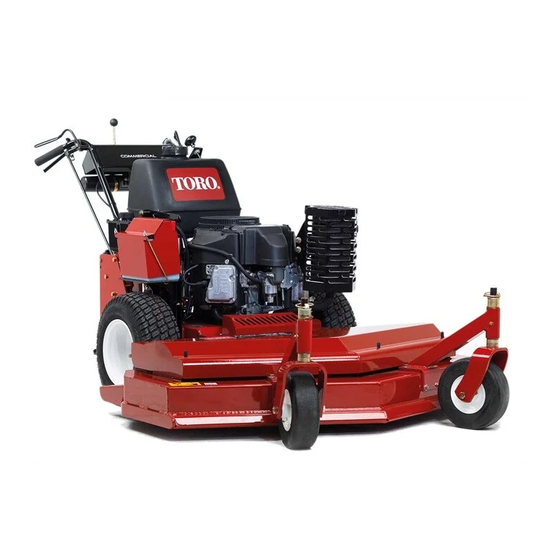
32RD, 36RD, and 48RD Mid-Size Rear-Discharge
Deck
Model No. 02710—Serial No. 312000001 and Up
Model No. 02711—Serial No. 312000001 and Up
Model No. 02712—Serial No. 312000001 and Up
These instructions must not be supplied to the customer.
These instructions cover the procedure for a dealer to
install a cutting deck (02710, 02711, or 02712) to a Mid
Size Power Unit (30069).
This equipment has been designed and constructed so
that, in so far as is reasonably practical, they meet the
safety requirements of European standard EN 836 and
they will not endanger the health and safety of those
working with them. This is, however, subject to the
machine being properly maintained and used according
to the conditions stated in the Operator's Manual, and
elsewhere, which have been found necessary as a result
of the research and testing of the Toro company.
WARNING
If the engine needs to be running to perform
any maintenance adjustments, keep hands, feet,
clothing, and parts of the body away from the
cutting unit and moving parts.
WARNING
Engine exhaust contains carbon monoxide, which
is an odorless, deadly poison that can kill you.
Do not run engine indoors or in an enclosed area.
Important: Read and understand these assembly
instructions before proceeding. Refer to the Parts
Catalog and Operator's Manual for the machine to
which these parts are to be fitted.
Important: Ensure that all lifting equipment is
in good condition and has a safe and adequate
capacity. Always seek assistance when lifting
awkward or heavy loads.
Important: Torque all fasteners to the specified
torque settings. The parts being fitted must not be
drilled, cut or altered in any way.
© 2012—The Toro® Company
8111 Lyndale Avenue South
Bloomington, MN 55420
1
Installing the Cutting Deck
Parts needed for this procedure:
1
Center discharge guard
2
Carriage bolt (M10 x 25 mm)
4
Washer (M8–17)
2
Locknut (M8)
8
Flange nut (3/8 inch)
1
Underside guard
2
Bolt (M8 x 25 mm)
1
Drive pulley guard
8
Bolt (3/8 x 1 inch)
2
Heavy washer (M10)
2
Nut (M10)
8
Curved washer
1
Drag shield
2
Spring washer (M10)
Procedure
1. Raise and support the traction unit using a suitable
lifting method.
2. Remove both wheels from the traction unit
(Figure 1).
Register at www.Toro.com.
Form No. 3367-846 Rev C
Setup Instructions
Original Instructions (EN)
All Rights Reserved
Advertisement

Related Manuals for Toro 02710


Summary of Contents for Toro 02710
- Page 1 These instructions must not be supplied to the customer. These instructions cover the procedure for a dealer to install a cutting deck (02710, 02711, or 02712) to a Mid Size Power Unit (30069). This equipment has been designed and constructed so...
- Page 2 Figure 3 Figure 1 1. Flange nut (3/8 inch) 3. Bolt (3/8 x 1 inch) 2. Curved washer 3. Remove the deck cover and the PTO engagement linkage rod before lifting and manoeuvring the rotary Note: Figure 3 shows the fasteners out side of the cutting deck into position against the power unit mowing unit to better illustrate which configuration (Figure 2).
- Page 3 the belt guide under the engine frame and adjust the setting of the rear axle depending on what height of belt guide. cut is required. 13. Install the traction wheels to the hubs and secure with drive wheel lug nuts. Torque Nuts to 122 - 129 N-m.
- Page 4 Directive, the dealer is required to verify the correct engine speed 2900 RPM when the power unit is connected to models 02710 and 02711 and 3500 RPM when the power unit is connected to model 02712. 2900/3500 RPM is the unloaded engine rpm, adjust with the PTO Off (Disengaged).