
Related Manuals for Toro TX 1300


Summary of Contents for Toro TX 1300
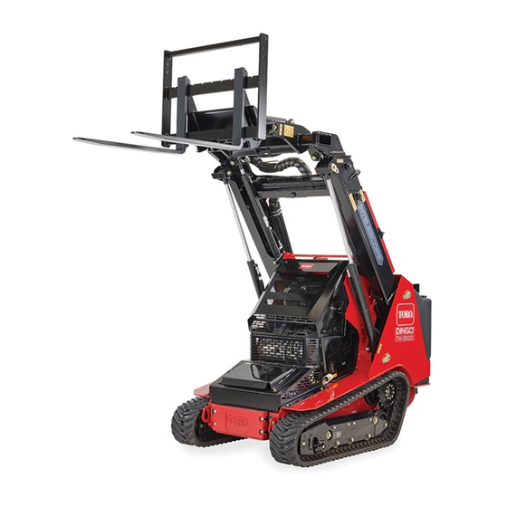
- Page 1 Form No. 3438-963 Rev A TX 1300 Compact Tool Carrier Model No. 22370—Serial No. 400000000 and Up *3438-963* Register at www.Toro.com. Original Instructions (EN)
- Page 2 Section 4442 or 4443 to use or operate the engine on additional information, contact an Authorized Service any forest-covered, brush-covered, or grass-covered Dealer or Toro Customer Service and have the model land unless the engine is equipped with a spark and serial numbers of your product ready.
-
Page 3: Table Of Contents
This manual uses 2 words to highlight information. Draining the Fuel Tank(s)........50 Important calls attention to special mechanical Electrical System Maintenance ......51 information and Note emphasizes general information Electrical System Safety ........51 worthy of special attention. Using the Battery-Disconnect Switch ....51 Servicing the Battery......... -
Page 4: Safety
Safety • Keep your hands and feet away from the moving components and attachments. • Do not operate the machine without the guards This machine has been designed in accordance with and other safety protective devices in place and ISO 20474-15:2019. working on the machine. -
Page 5: Safety And Instructional Decals
Safety and Instructional Decals Safety decals and instructions are easily visible to the operator and are located near any area of potential danger. Replace any decal that is damaged or missing. decal115-4855 115-4855 1. Hot surface/burn hazard—wear protective gloves when handling the hydraulic couplers and read the Operator's decalbatterysymbols Battery Symbols... - Page 6 decal117-3276 117-3276 1. Engine coolant under 3. Warning—do not touch the pressure hot surface. 2. Explosion hazard—read 4. Warning—read the the Operator's Manual. Operator's Manual. decal125-6694 125–6694 1. Tie down location decal120-0625 120-0625 1. Pinch point, hand—keep hands away. decal125-8483 125-8483 1.
- Page 7 decal139-1159 139-1159 1. Warning—keep bystanders away. decal139-1162 decal131-8026 139-1162 131-8026 1. Warning—read the 2. Tipping hazard—do not 1. Battery 3. On Operator’s Manual for drive the machine with the power—disconnect the bucket maximum load raised or the arms 2. Off 4.
- Page 8 decal139-1173 139-1173 1. High-pressure fluid hazard, injection into the body—read the Operator’s Manual before performing maintenance. decal145-4273 decal145-4274 145-4273 145-4274 1. Retract the hydraulic 4. Extend the arms 1. Read the Operator’s 9. Engine oil cylinder (optional) (telescoping model only) Manual before performing maintenance.
- Page 9 decal131-0708 131-0708 3. Move rearward 1. Move forward 4. Turn right 2. Turn left decal144-4253 144-4253 1. Parking brake—engaged 5. Engine—stop 2. Parking brake—disengaged 6. Engine—run 3. Fast 7. Engine—start 4. Slow 8. Horn...
- Page 10 decal145-0637 145-0637 1. Warning—read the Operator's Manual. 7. Cutting/severing hazard of hand or foot—wait for all moving parts to stop before servicing; keep away from moving parts; keep all guards and shields in place. 2. Warning—receive training before operating the machine. 8.
-
Page 11: Product Overview
Product Overview g318043 Figure 3 1. Hood 5. Lower loader arm 9. Control panel 13. Fuel gauge 2. Auxiliary hydraulic couplers 6. Upper loader arm 10. Hydraulic tank 14. Tie-down point 3. Mount plate 7. Track 11. Auxiliary hydraulics lock 15. -
Page 12: Controls
Controls Reference Bar When driving the traction unit, use the reference bar as a handle and a leverage point for controlling the Control Panel traction control and the joystick lever. To ensure smooth, controlled operation, do not take your hands Become familiar with all the controls before you start off the reference bars while operating the machine. - Page 13 Loader Arm/Attachment-Tilt Lever • To turn right, rotate the traction control clockwise. Slowly move the lever to operate the loader arms and tilt the attachment. Note: The detent (float) position allows attachments such as the leveler and the hydraulic blade to follow the contours of the ground (i.e., float) when grading.
- Page 14 Loader-Valve Lock Joystick Controls The loader-valve lock secures the loader arm/attachment-tilt lever so that you cannot push it forward. This helps to ensure that no one accidentally lowers the loader arms during maintenance. Secure the loader valve with the lock, in addition to the cylinder locks, any time you need to shut off the machine with the loader arms raised.
-
Page 15: Infocenter Display
Fuel Gauge InfoCenter Icon Descriptions This gauge measures the amount of fuel in the fuel Menu access tank(s). Next Previous Scroll down g371278 Enter Figure 14 Change the next value in the list InfoCenter Display Increase The InfoCenter LCD display shows information about Decrease your machine, such as the operating status, various diagnostics and other information about the machine. - Page 16 Using the Menus InfoCenter Icon Descriptions (cont'd.) To access the InfoCenter menu system, press the menu access button while at the main screen. Parking brake This will bring you to the main menu. Refer to the following tables for a synopsis of the options available from the menus: Engine Main Menu...
- Page 17 Service Settings Menu Item Description Menu Item Description Hours Lists the total number of hours Units Controls the units used on the that the machine, engine, and InfoCenter; the menu choices auxiliary hydraulics have been are Imperial or Metric. on, as well as the number of Language Controls the language used hours for engine service and...
-
Page 18: Specifications
Authorized Service Dealer or authorized Toro Note: If the InfoCenter accepts the PIN code distributor or go to www.Toro.com for a list of all and the protected menu is unlocked, the word Toro-manufactured attachments and accessories. “PIN” displays in the upper right corner of the To ensure optimum performance, use genuine Toro screen. -
Page 19: Before Operation
Fuel Safety Operation • Use extreme care when handling fuel. It is flammable and its vapors are explosive. Note: Determine the left and right sides of the • Extinguish all cigarettes, cigars, pipes, and other machine from the normal operating position. sources of ignition. -
Page 20: Performing Daily Maintenance
Biodiesel Ready Performing Daily Maintenance This machine can also use a biodiesel blended fuel of up to B5 (5% biodiesel, 95% petrodiesel). The Before starting the machine each day, perform the petrodiesel portion should be low or ultra low sulfur. Each Use/Daily procedures listed in the Maintenance Observe the following precautions:... - Page 21 Slope Safety • Wear appropriate clothing including eye protection, long pants, substantial slip-resistant footwear, and • Operate the machine up and down slopes with hearing protection; also wear a respirator or dust the heavy end of the machine uphill. Weight mask in dusty conditions.
-
Page 22: Starting The Engine
Starting the Engine The machine could suddenly roll over if a track goes over the edge or the edge caves in. Maintain Ensure that the battery-disconnect switch a safe distance between the machine and any is in the O position; refer to Using the hazard. -
Page 23: Shutting Off The Engine
Check the receiver plate and Installing an Attachment clean it if necessary. Important: Use only Toro-approved attachments. WARNING Attachments can change the stability and the operating characteristics of the machine. The If you do not fully seat the quick-attach... - Page 24 CAUTION Hydraulic couplers, hydraulic lines/valves, and hydraulic fluid may be hot. If you contact hot components, you may be burned. • Wear gloves when operating the hydraulic couplers. • Allow the machine to cool before touching hydraulic components. • Do not touch hydraulic fluid spills. If the attachment requires hydraulics for operation, connect the hydraulic hoses as follows: Shut off the engine and remove the key.
-
Page 25: Understanding The Smart Load System
Removing an Attachment Understanding the Smart Park the machine on a level surface. Load System Lower the attachment to the ground. The Smart Load system also measures the hydraulic Shut off the engine and remove the key. pressure in the loader arm cylinders to determine the maximum reach. -
Page 26: Diesel Particulate Filter (Dpf) Regeneration
Diesel Particulate Filter (DPF) Regeneration Understanding DPF Regeneration The diesel particulate filter (DPF) is part of the exhaust system. The diesel-oxidation catalyst of the DPF reduces harmful gasses, and the soot filter removes soot from the engine exhaust. The DPF regeneration process uses heat from the engine exhaust to incinerate the soot accumulated on the soot filter, converting the soot to ash, and clears the channels of the soot filter so that filtered engine... - Page 27 DPF Soot Accumulation • Over time, the diesel particulate filter accumulates soot in the soot filter. The computer for the engine monitors the soot level in the DPF. • When enough soot accumulates, the computer informs you that it is time to regenerate the DPF. •...
- Page 28 DPF Ash Accumulation • The lighter ash is discharged through the exhaust system; the heavier ash collects in the soot filter. • Ash is a residue of the regeneration process. Over time, the diesel particulate filter accumulates ash that does not discharge with the engine exhaust. •...
- Page 29 Types of DPF Regeneration Types of DPF regeneration that are performed while the machine is operating: Type of Regeneration Conditions that cause DPF regeneration DPF description of operation • Passive Occurs during normal operation of the machine at The InfoCenter does not display an icon high-engine speed or high-engine load indicating passive regeneration.
- Page 30 Types of DPF regeneration that require you to park the machine: (cont'd.) Type of Regeneration Conditions that cause DPF regeneration DPF description of operation • Recovery Occurs because the operator ignored requests for When the reset-standby/parked or recovery a parked regeneration and continued operating the regeneration icon #190 ADVISORY...
- Page 31 Passive DPF Regeneration DPF Operation Table • Passive regeneration occurs as part of normal State Description engine operation. Normal The DPF is in normal-operating mode—passive regeneration. • While operating the machine, run the engine at full-engine speed and high load when possible to Assist Regen The engine computer is performing an assist regeneration.
- Page 32 Periodic Reset Regeneration Allowing a Reset Regeneration If the engine has not completed a successful Reset, The InfoCenter displays the high exhaust-temperature Parked, or Recovery regeneration in the previous 100 icon when the reset regeneration is in process. hours of engine operation, the engine computer will attempt to perform a reset regeneration.
- Page 33 Parked or Recovery Regeneration DPF Status-Limitation • If the engine computer requests a parked • When the engine computer requests either a regeneration or is processing a parked parked regeneration or a recovery regeneration, regeneration, the P option locks and ARKED EGEN the regeneration request icon...
- Page 34 Ensure that the machine has at least the At the I DPF R screen, press the NITIATE EGEN specified amount fuel in the tank for the type of right button to continue. regeneration you are performing: • Parked Regeneration: 1/4 tank of fuel •...
- Page 35 The engine computer checks the engine state When the engine computer completes a and fault information. The InfoCenter may parked or recovery regeneration, the InfoCenter display the following messages: displays A #183; if it fails, the InfoCenter DVISORY displays A #184.
-
Page 36: After Operation
Moving a Non-Functioning After Operation Machine After Operation Safety Important: Do not tow or pull the machine without first opening the tow valves, or you will damage the hydraulic system. General Safety Shut off the engine and remove the key. •... -
Page 37: Hauling The Machine
Tighten the nut to release the brake. you or bystanders avoid injury. Refer to your local ordinances for trailer and tie-down requirements. WARNING Driving on the street or roadway without turn signals, lights, reflective markings, or a slow-moving-vehicle emblem is dangerous and can lead to accidents causing personal injury. - Page 38 Loading the Machine Important: Do not use the tie-down loops to lift the machine. WARNING Loading or unloading a machine onto a trailer or truck increases the possibility of tip-over and could cause serious injury or death. • Use extreme caution when operating a machine on a ramp.
-
Page 39: Lifting The Machine
Lifting the Machine Remove any attachments and lift the machine using the 4 lift points. Do not exceed a 30-degree angle when lifting the machine; use the minimum chain lengths provided below. g371939 Figure 56 1. Chain length for rear lift point (2)—143.0 cm (56.3 inches) 2. -
Page 40: Maintenance
Attachments can change the stability and the machine. operating characteristics of the machine. • Use jack stands to support the components when • Use only genuine Toro replacement parts. required. • If any maintenance or repair requires the loader • Carefully release pressure from components arms to be in the raised position, secure the arms with stored energy;... - Page 41 • Check the fuel lines and connections for deterioration, damage, or loose connections. Every 400 hours • Replace the hydraulic oil and filters (if not using Toro fluid). • Service the air cleaner. (Service more frequently in extremely dusty or dirty conditions).
-
Page 42: Pre-Maintenance Procedures
Pre-Maintenance Slide the cylinder lock over the lift-cylinder rod. Procedures Using the Cylinder Locks WARNING The loader arms may lower when in the raised position, crushing anyone under them. Install the cylinder lock(s) before performing maintenance that requires raised loader arms. Installing the Cylinder Locks g267536 Figure 58... -
Page 43: Accessing Internal Components
Removing and Storing the Accessing Internal Cylinder Locks Components Important: Remove the cylinder locks from the rods and fully secure them in the storage position WARNING before operating the machine. Opening or removing covers, hoods, and Start the engine. screens while the engine is running could allow you to contact moving parts, seriously Raise the loader arms to the fully raised position. -
Page 44: Removing The Front Cover
Removing the Rear Cover Removing the Bottom Plate Remove the 2 bolts securing the top of the rear Remove the 2 bolts securing the bottom plate. cover. g359291 Figure 63 Remove the bottom plate. Removing the Front Cover g359278 Figure 61 Raise the loader arms and secure them with the cylinder locks. -
Page 45: Removing The Front Cover Assembly
Removing the Front Cover Lubrication Assembly Greasing the Machine Raise the loader arms and secure them with the cylinder locks. Service Interval: Before each use or daily (Grease Open the hood. immediately after every washing.) Remove the 4 bolts securing the cover assembly Grease Type: General-purpose grease. -
Page 46: Engine Maintenance
Engine Maintenance Ensure that the cover seats correctly and seals with the air-cleaner body. Engine Safety Servicing the Air Cleaner • Shut off the engine before checking the oil or Note: If the foam gasket in the cover is damaged, adding oil to the crankcase. -
Page 47: Servicing The Engine Oil
SAE 10W-30 or 5W-30 (all temperatures) • SAE 15W-40 (above 0° F) Note: Toro Premium Engine oil is available from your Authorized Service Dealer. Checking the Engine-Oil Level Park the machine on a level surface, engage the parking brake, and lower the loader arms. - Page 48 Changing the Engine Oil and Filter Open the hood. Remove any attachments. Remove the left screen; refer to Removing the Side Screens (page 45). Start the engine and let it run for 5 minutes. Place a shallow pan or rag under the filter to Note: This warms the oil so that it drains better.
-
Page 49: Servicing The Diesel-Oxidation Catalyst (Doc) And The Soot Filter
Servicing the Fuel System Diesel-Oxidation Catalyst Maintenance (DOC) and the Soot Filter DANGER Service Interval: Every 3,000 hours or if engine In certain conditions, fuel is extremely faults 3251 3720 flammable and highly explosive. A fire or 0, or 3720 16 display in the explosion from fuel can burn you and others InfoCenter. -
Page 50: Replacing The Water Separator Filter
Replacing the Water Bleeding the Fuel System Separator Filter You must bleed the fuel system before starting the engine if any of the following situations have occurred: Service Interval: Every 500 hours • Initial startup of a new machine Park the machine on a level surface, engage the •... -
Page 51: Electrical System Maintenance
Servicing the Battery Electrical System Maintenance Service Interval: Every 50 hours—Check the battery condition. Electrical System Safety Removing the Battery • Disconnect the battery before making any repairs; WARNING refer to Using the Battery-Disconnect Switch (page 51). Incorrect battery cable routing could damage the machine and cables, causing sparks. - Page 52 Removing the Battery (page 51). Coat the battery posts and cable connectors with Grafo 112X (skin-over) grease (Toro Part No. Charge the battery for 4 to 8 hours at a rate of 3 505-47) or petroleum jelly to prevent corrosion.
-
Page 53: Jump-Starting The Machine
Installing the Battery Jump-Starting the Machine WARNING WARNING Incorrect battery cable routing could damage Jump-starting the battery can produce gasses the machine and cables, causing sparks. that can explode. Sparks can cause the battery gasses to Do not smoke near the battery, and keep explode, resulting in personal injury. - Page 54 systems are off and at the same rated system voltage. These instructions are for negative ground systems only. Connect the positive (+) cable to the positive (+) terminal of the discharged battery that is wired to the starter or solenoid as shown in Figure g012785 Figure 81...
-
Page 55: Servicing The Fuses
Servicing the Fuses The electrical system is protected by fuses. It requires no maintenance; however, if a fuse blows, check the component/circuit for a malfunction or a short. g362178 Figure 82 Fuse Layout Horn Joystick Attachment Power Accessory Tec Power (10 A) (5 A) (20 A) -
Page 56: Drive System Maintenance
Drive System Maintenance Servicing the Tracks Service Interval: After the first 8 hours—Check and adjust the track tension. After the first 50 hours—Check and adjust the track tension. g361234 Every 50 hours—Check and adjust the track Figure 83 tension. 1. Sectional drive sprocket 4. - Page 57 Replacing the Tracks Loosen the bolts on the rear cover and remove the cover. Removing the Tracks Remove any attachments. Park the machine on a level surface, ensuring that only 1 sprocket half is engaged with the track. g363402 Figure 85 1.
- Page 58 Loosen the jam nut and turn the tensioning Remove the track from the track frame, drive screw to release the tension. hub, then front wheel. Installing the Tracks Wrap the new track around the front wheel. g363401 Figure 89 1. Tensioning screw 2.
-
Page 59: Cooling System Maintenance
Cooling System Apply thread-locking compound to the bolts of the drive sprocket half that you removed and Maintenance install the other sprocket half. Torque the bolts to 80 to 99 N∙m (59 to 73 ft-lb). Cooling System Safety • Swallowing engine coolant can cause poisoning; keep out of reach from children and pets. -
Page 60: Changing The Engine Coolant
Checking the Engine-Coolant Belt Maintenance Level Checking the Service Interval: Before each use or daily—Check the coolant level in the expansion Alternator-Belt Tension tank. The cooling system is filled with a 50/50 solution of Service Interval: Every 100 hours water and permanent ethylene-glycol antifreeze. Apply 44 N (10 lb) of force to the alternator belt, Park the machine on a level surface, lower the midway between the pulleys. -
Page 61: Controls System Maintenance
Controls System Hydraulic System Maintenance Maintenance Adjusting the Controls Hydraulic System Safety • Seek immediate medical attention if fluid is injected The factory adjusts the controls before shipping the into skin. Injected fluid must be surgically removed machine. However, after many hours of use, you within a few hours by a doctor. -
Page 62: Hydraulic-Fluid Specifications
Toro PX Extended Life Hydraulic Fluid (refer to your Authorized Service Dealer for more information) • If either of the above Toro fluids are not available, you may use another Universal Tractor Hydraulic Fluid (UTHF), but they must be only conventional, petroleum-based products. The... -
Page 63: Replacing The Hydraulic Filters
If the level is low, add enough fluid to raise it to Check the fluid level in the hydraulic tank; refer the proper level. Checking the Hydraulic-Fluid Level (page and add fluid to raise the level to mark on Install the filler cap. dipstick. -
Page 64: Loader Maintenance
Loader Maintenance Cleaning Removing Debris Torquing the Loader Arm Adjustment Screws Service Interval: Before each use or daily Important: Operating the engine with blocked Service Interval: Every 25 hours screens and/or cooling shrouds removed will Check the torque whenever the lower loader arms result in engine damage from overheating. -
Page 65: Cleaning The Chassis
Cleaning the Chassis Storage Service Interval: Every 100 hours—Check for dirt Storage Safety buildup in the chassis. (More often in dirty conditions.) • Shut off the engine, remove the key, wait for all Over time, the chassis under the engine collects dirt moving parts to stop, and allow the machine to and debris that must be removed. -
Page 66: Troubleshooting
Troubleshooting Problem Possible Cause Corrective Action The engine does not start. 1. Dirt, water, stale fuel, or incorrect fuel 1. Drain and flush the fuel system; add is in the fuel system. fresh fuel. 2. The fuel filter is clogged. 2. - Page 67 Problem Possible Cause Corrective Action The machine does not drive. 1. The parking brake is engaged. 1. Disengage the parking brake. 2. The hydraulic-fluid level is low. 2. Add hydraulic fluid to the reservoir. 3. The hydraulic system is damaged. 3.
- Page 68 Notes:...
- Page 69 Notes:...
- Page 70 The Toro Company (“Toro”) respects your privacy. When you purchase our products, we may collect certain personal information about you, either directly from you or through your local Toro company or dealer. Toro uses this information to fulfil contractual obligations - such as to register your warranty, process your warranty claim or to contact you in the event of a product recall - and for legitimate business purposes - such as to gauge customer satisfaction, improve our products or provide you with product information which may be of interest.
- Page 71 While the exposure from Toro products may be negligible or well within the “no significant risk” range, out of an abundance of caution, Toro has elected to provide the Prop 65 warnings. Moreover, if Toro does not provide these warnings, it could be sued by the State of California or by private parties seeking to enforce Prop 65 and subject to substantial penalties.