Mitsubishi Electric MELSEQ FX3S Series User Manual
Hide thumbs
Also See for MELSEQ FX3S Series:
- User manual (282 pages) ,
- Quick start manual (19 pages) ,
- Hardware manual (4 pages)
Table of Contents
Advertisement
Quick Links
FX
SERIES PROGRAMMABLE CONTROLLERS
3S
USER'S MANUAL
Hardware Edition
Main Unit
AC Power Type
FX
-MR/ES
3S
FX
-MT/ES
3S
FX
-MT/ESS
3S
FX
-30MR/ES-2AD
3S
FX
-30MT/ES-2AD
3S
FX
-30MT/ESS-2AD
3S
DC Power Type
FX
-MR/DS
3S
FX
-MT/DS
3S
FX
-MT/DSS
3S
Display Module
FX
-5DM
3S
Memory Cassette
FX
-EEPROM-32L
3G
Advertisement
Table of Contents
Troubleshooting

Related Manuals for Mitsubishi Electric MELSEQ FX3S Series


Summary of Contents for Mitsubishi Electric MELSEQ FX3S Series
- Page 1 SERIES PROGRAMMABLE CONTROLLERS USER'S MANUAL Hardware Edition Main Unit AC Power Type -MR/ES -MT/ES -MT/ESS -30MR/ES-2AD -30MT/ES-2AD -30MT/ESS-2AD DC Power Type -MR/DS -MT/DS -MT/DSS Display Module -5DM Memory Cassette -EEPROM-32L...
- Page 3 Safety Precautions Safety Precautions (Read these precautions before use.) (Read these precautions before use.) Before installation, operation, maintenance or inspection of this product, thoroughly read through and understand this manual and all of the associated manuals. Also, take care to handle the module properly and safely.
- Page 4 Safety Precautions (Read these precautions before use.) 3. INSTALLATION PRECAUTIONS Reference • Make sure to cut off all phases of the power supply externally before attempting installation or wiring work. Failure to do so may cause electric shock or damage to the product. Reference •...
- Page 5 Safety Precautions (Read these precautions before use.) 4. WIRING PRECAUTIONS Reference • Make sure to cut off all phases of the power supply externally before attempting installation or wiring work. Failure to do so may cause electric shock or damage to the product. •...
- Page 6 • Do not disassemble or modify the PLC. Doing so may cause fire, equipment failures, or malfunctions. For repair, contact your local Mitsubishi Electric representative. • Turn off the power to the PLC before connecting or disconnecting any connection cable.
-
Page 7: Safety Precautions
This manual confers no industrial property rights or any rights of any other kind, nor does it confer any patent licenses. Mitsubishi Electric Corporation cannot be held responsible for any problems involving industrial property rights which may occur as a result of using the contents noted in this manual. © 2013 MITSUBISHI ELECTRIC CORPORATION... - Page 8 • Since the examples indicated by this manual, technical bulletin, catalog, etc. are used as a reference, please use it after confirming the function and safety of the equipment and system. Mitsubishi Electric will accept no responsibility for actual use of the product based on these illustrative examples.
-
Page 9: Table Of Contents
Series Programmable Controllers User's Manual - Hardware Edition Table of Contents Table of Contents SAFETY PRECAUTIONS ....................(1) Standards..........................10 Certification of UL, cUL standards ..................... 10 Compliance with EC directive (CE Marking) ..................10 Requirement for Compliance with EMC directive .................. 10 Requirement for Compliance with LVD directive ................... - Page 10 Series Programmable Controllers User's Manual - Hardware Edition Table of Contents 4.7 Terminal Layout ..........................37 4.7.1 Interpretation of terminal block layout.................... 37 4.7.2 FX -10M........................... 38 4.7.3 FX -14M........................... 38 -20M........................... 39 4.7.4 FX 4.7.5 FX -30M........................... 39 5. Version Information and Peripheral Equipment Connectability 5.1 Version Information ........................
- Page 11 Series Programmable Controllers User's Manual - Hardware Edition Table of Contents 8. Preparation for Wiring and Power Supply Wiring Procedures 8.1 Preparation for Wiring ........................66 8.1.1 Wiring procedures ......................... 66 8.2 Cable Connecting Procedures ...................... 67 8.2.1 Terminal block [Main unit]......................67 8.2.2 Terminal block (for European) [expansion board and special adapters] ........
- Page 12 Series Programmable Controllers User's Manual - Hardware Edition Table of Contents 11. Use of Built-in Analog 11.1 Outline............................99 11.2 Built-in variable analog potentiometer function ................99 11.2.1 Outline of functions........................99 11.2.2 Applicable PLC ..........................99 11.2.3 Special data register........................99 11.2.4 Use example of variable analog potentiometer .................
- Page 13 Series Programmable Controllers User's Manual - Hardware Edition Table of Contents 14.3 Operation and Test [Power ON and PLC Running] ..............130 14.3.1 Self-diagnostic function ......................130 14.3.2 Test functions ..........................130 14.3.3 Program modification function ....................130 14.4 Maintenance and Periodic Inspection ..................131 14.4.1 Periodic inspection ........................
- Page 14 Series Programmable Controllers User's Manual - Hardware Edition Table of Contents 16.5 Monitor/Test ..........................157 16.5.1 Relevant devices ........................157 16.5.2 Selecting a device ........................157 16.5.3 When "Input (X)", "Output (Y)", "Auxiliary relay (M)" or "State (S)" is selected ......158 16.5.4 When "Timer (T)"...
- Page 15 Series Programmable Controllers User's Manual - Hardware Edition Table of Contents Appendix A: Special Device List Appendix A-1 Special Auxiliary Relay (M8000 to M8511) ............187 Appendix A-2 Special Data Register (D8000 to D8511) ............193 Appendix A-3 Analog expansion boards [M8260 to M8269 and D8260 to D8269] ....198 Appendix A-3-1 Special auxiliary relays (M8260 to M8269)..............
-
Page 16: Standards
EC directive. Compliance to EMC directive and LVD directive of the entire mechanical module should be checked by the user / manufacturer. For more details please contact to the local Mitsubishi Electric sales site. Requirement for Compliance with EMC directive... -
Page 17: Requirement For Compliance With Lvd Directive
Series Programmable Controllers User's Manual - Hardware Edition Standards Type: Programmable Controller (Open Type Equipment) Models: MELSEC FX series, FX series, FX series manufactured from June 1st, 2005 -232ADP -485ADP -4AD-ADP -4DA-ADP -4AD-PT-ADP -4AD-TC-ADP from April 1st, 2007 -232ADP-MB -485ADP-MB from December 1st, 2007 -4AD-PTW-ADP -4AD-PNK-ADP... -
Page 18: Caution For Compliance With Ec Directive
(integral with sensors or actuators), these users should follow those manufacturers' installation requirements. Mitsubishi Electric recommends that shielded cables be used. If NO other EMC protection is provided, users may experience temporary loss or accuracy between +10% / -10% in very heavy industrial areas. -
Page 19: Introduction
Series Programmable Controllers 1 Introduction User's Manual - Hardware Edition 1.1 Introduction of Manuals Introduction This manual explains the procedures for selecting the system components, main unit specifications and procedures for installing the main unit, and procedures for operating the display module etc. FX PLCs can make various kinds of control in combination with the main unit functions and many extension devices (expansion board and special adapters). -
Page 20: Manual Organization And Position Of This Manual
Series Programmable Controllers 1 Introduction User's Manual - Hardware Edition 1.1 Introduction of Manuals 1.1.2 Manual organization and position of this manual This manual describes detail on the hardware, including the system configuration, installation and wiring. The instructions, communication control, analog control and positioning control are explained in separate manuals. -
Page 21: List Of Manuals
Series Programmable Controllers 1 Introduction User's Manual - Hardware Edition 1.1 Introduction of Manuals 1.1.3 List of manuals Series PLC main units supplied only with the hardware manual. For the details of the hardware of FX Series, refer to this manual. For instructions for programming and hardware information on special function devices, refer to the relevant manuals. - Page 22 Series Programmable Controllers 1 Introduction User's Manual - Hardware Edition 1.1 Introduction of Manuals Manual Model Manual Name Contents Number Code RS-232C/RS-422/RS-485 When using each product, refer also to the User's Manual - Hardware Edition for the PLC main unit to be installed and FX Series User's Manual - Data Communication Edition.
- Page 23 Series Programmable Controllers 1 Introduction User's Manual - Hardware Edition 1.1 Introduction of Manuals Manual Model Manual Name Contents Number Code Analog output When using each product, refer to the User's Manual - Hardware Edition for the PLC main unit to be installed and FX Series User's Manual - Analog Control Edition.
-
Page 24: Generic Names And Abbreviations Used In Manuals
Series Programmable Controllers 1 Introduction User's Manual - Hardware Edition 1.2 Generic Names and Abbreviations Used in Manuals Generic Names and Abbreviations Used in Manuals Abbreviation/generic name Description PLCs Series Generic name for FX Series PLCs Series Generic name for FX Series PLCs Series Generic name for FX... -
Page 25: Features And Part Names
Series Programmable Controllers 2 Features and Part Names User's Manual - Hardware Edition 2.1 Major Features Features and Part Names Major Features 1. Basic functions 2. Input/output high-speed processing functions of main unit [Up to 30 input/output points] Main units are available in models of 10, 14, 20 [High-speed counter function] and 30 total input/output points. - Page 26 Series Programmable Controllers 2 Features and Part Names User's Manual - Hardware Edition 2.1 Major Features 3. Display functions (display module) 5. Analog functions (Supported in Ver. 1.20 or later) The expansion board and special adapter for each analog function are connected. -5DM Display Module (option) can be →...
-
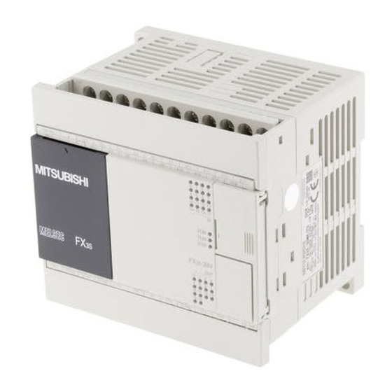
Page 27: Names And Functions Of Parts
Series Programmable Controllers 2 Features and Part Names User's Manual - Hardware Edition 2.2 Names and Functions of Parts Names and Functions of Parts 2.2.1 Front Panel Factory default configuration (standard) [10] [1] Top cover Mount the expansion board, display module and memory cassette under this cover. [2] Terminal names The signal names for power supply, input and output terminals are shown. - Page 28 Series Programmable Controllers 2 Features and Part Names User's Manual - Hardware Edition 2.2 Names and Functions of Parts When the top covers are open □ □ [In the case of FX -30M -2AD] [1] Optional equipment connector These holes are designed to secure the expansion board, display module and memory cassette with screws.
-
Page 29: Sides
Series Programmable Controllers 2 Features and Part Names User's Manual - Hardware Edition 2.2 Names and Functions of Parts 2.2.2 Sides [AC Power Type] Left side Right side [ 2 ] [ 3 ] [ 4 ] [ 5 ] [DC power type] Left side Right side... -
Page 30: Introduction Of Products
Series Programmable Controllers 3 Introduction of Products User's Manual - Hardware Edition 3.1 List of Products and Interpretation of Model Names Introduction of Products List of Products and Interpretation of Model Names The following system configuration is classified into product groups A to F in the product introduction sections given below. -
Page 31: Main Units
Series Programmable Controllers 3 Introduction of Products User's Manual - Hardware Edition 3.1 List of Products and Interpretation of Model Names 3.1.1 Main units The main unit incorporates a CPU, memory, input and output terminals and power supply. To establish a system, at least one main unit is necessary. Incorporating power supply •... -
Page 32: Expansion Boards
Series Programmable Controllers 3 Introduction of Products User's Manual - Hardware Edition 3.1 List of Products and Interpretation of Model Names 3.1.2 Expansion boards Model name Description 4 points general-purpose input -4EX-BD 2 points transistor output -2EYT-BD -232-BD For RS-232C communication -422-BD For RS-422 communication -485-BD... -
Page 33: Connector Types And Cables For Program Communication
Series Programmable Controllers 3 Introduction of Products User's Manual - Hardware Edition 3.2 Connector Types and Cables for Program Communication Connector Types and Cables for Program Communication RS-232C/RS-422 cable Connection cabling Connection cabling for Peripheral device connector extension device FX-232AWC-H RS-232C RS-422 FX-30P... -
Page 34: Programming Tool
Series Programmable Controllers 3 Introduction of Products User's Manual - Hardware Edition 3.2 Connector Types and Cables for Program Communication 3.2.1 Programming tool The following programming tools support FX Series PLCs. → For more information, refer to 5. Version Information and Peripheral Equipment Connectability. Model name Description GX Works2... -
Page 35: Specifications, External Dimensions And Terminal Layout (Main Units)
Series Programmable Controllers 4 Specifications, External Dimensions and Terminal Layout (Main Units) User's Manual - Hardware Edition 4.1 Generic Specifications Specifications, External Dimensions and Terminal Layout (Main Units) This chapter explains the specifications, external dimensions and terminal layout of the main units. Generic Specifications The generic specifications for the main unit are explained below. -
Page 36: Dielectric Withstand Voltage Test And Insulation Resistance Test
Series Programmable Controllers 4 Specifications, External Dimensions and Terminal Layout (Main Units) User's Manual - Hardware Edition 4.2 Power Supply Specifications 4.1.1 Dielectric withstand voltage test and insulation resistance test Perform dielectric withstand voltage test and insulation resistance test at the following voltage between each terminals and the main unit ground terminal. -
Page 37: Input Specifications
Series Programmable Controllers 4 Specifications, External Dimensions and Terminal Layout (Main Units) User's Manual - Hardware Edition 4.3 Input Specifications Input Specifications The input specifications for the main unit are explained below. → For the specifications of the built-in analog input, refer to Chapter 11. 4.3.1 24 V DC Input (sink/source) →... -
Page 38: Output Specifications
Series Programmable Controllers 4 Specifications, External Dimensions and Terminal Layout (Main Units) User's Manual - Hardware Edition 4.4 Output Specifications Output Specifications The output specifications for the main unit are explained below. 4.4.1 Relay output specifications Relay output specification Item -10MR... -
Page 39: Transistor Output Specifications
Series Programmable Controllers 4 Specifications, External Dimensions and Terminal Layout (Main Units) User's Manual - Hardware Edition 4.4 Output Specifications 4.4.2 Transistor output specifications Transistor output specification Item -10MT -14MT -20MT -30MT Number of output points 4 points 6 points 8 points 14 points Output connecting type... -
Page 40: Performance Specifications
Series Programmable Controllers 4 Specifications, External Dimensions and Terminal Layout (Main Units) User's Manual - Hardware Edition 4.5 Performance Specifications Performance Specifications The performance specifications for the main unit are explained below. Item Performance Operation control system Stored program repetitive operation system with interruption function. Batch processing system (when END instruction is executed) Input/output control system Input/output refresh instruction and pulse catch function are provided. - Page 41 Series Programmable Controllers 4 Specifications, External Dimensions and Terminal Layout (Main Units) User's Manual - Hardware Edition 4.5 Performance Specifications Item Performance 1-phase 1-count input in both directions (32 bits up/down) C235 to C245 (EEPROM keep) 1-phase 2-count input in both High-speed counter directions (32 bits up/down) C246 to C250...
-
Page 42: External Dimensions (Weight/Accessories/Installation)
Series Programmable Controllers 4 Specifications, External Dimensions and Terminal Layout (Main Units) User's Manual - Hardware Edition 4.6 External Dimensions (Weight/Accessories/Installation) External Dimensions (Weight/Accessories/Installation) The external dimensions of the main unit are explained. 4.6.1 Main units 2-φ4.5 mounting holes Unit: mm (inches) W1 (Mounting hole pitches) 8 (0.32'') 75 (2.96") : AC power type... -
Page 43: Terminal Layout
Series Programmable Controllers 4 Specifications, External Dimensions and Terminal Layout (Main Units) User's Manual - Hardware Edition 4.7 Terminal Layout Terminal Layout The terminal layout of the main unit are explained. 4.7.1 Interpretation of terminal block layout Input terminals Power supply terminals [•] Vacant terminal Output terminals -30MR/ES, FX... -
Page 44: Fx 3S -10M
Series Programmable Controllers 4 Specifications, External Dimensions and Terminal Layout (Main Units) User's Manual - Hardware Edition 4.7 Terminal Layout 4.7.2 -10M • AC power type • • -10MR/ES, FX -10MT/ES • COM0 COM1 COM2 COM3 • -10MT/ESS • +V1 +V2 •... -
Page 45: Fx 3S -20M
Series Programmable Controllers 4 Specifications, External Dimensions and Terminal Layout (Main Units) User's Manual - Hardware Edition 4.7 Terminal Layout 4.7.4 -20M • AC power type -20MR/ES, FX -20MT/ES • COM0 COM1 COM2 COM3 COM4 -20MT/ESS • +V1 +V2 +V3 +V4 •... -
Page 46: Version Information And Peripheral Equipment Connectability
Series Programmable Controllers 5 Version Information and Peripheral Equipment Connectability User's Manual - Hardware Edition 5.1 Version Information Version Information and Peripheral Equipment Connectability Version Information 5.1.1 Manufacturer's serial number check method The year and month of production of the product can be checked on the nameplate, and "LOT" indicated on the front of the product. -
Page 47: Version Check Method
Series Programmable Controllers 5 Version Information and Peripheral Equipment Connectability User's Manual - Hardware Edition 5.2 Programming Tool Applicability 5.1.2 Version check method The PLC version number can be checked by reading the last three digits of device D8001/D8101. D8001/D8101 PLC type and Version information (Example: Ver. -
Page 48: Program Transfer Speed And Programming Tools
Series Programmable Controllers 5 Version Information and Peripheral Equipment Connectability User's Manual - Hardware Edition 5.2 Programming Tool Applicability 5.2.3 Program transfer speed and programming tools 1. Built-in USB communication The FX PLC has a built-in USB communication port, and performs program writing, program reading and monitoring at high speed (12 Mbps) with a personal computer that supports USB. -
Page 49: Cautions On Write During Run
Series Programmable Controllers 5 Version Information and Peripheral Equipment Connectability User's Manual - Hardware Edition 5.2 Programming Tool Applicability 5.2.5 Cautions on write during RUN Write during RUN (program changes during RUN) is available in the FX PLC when GX Works2 is used. However, list programs and SFC programs cannot be written during RUN. - Page 50 Series Programmable Controllers 5 Version Information and Peripheral Equipment Connectability User's Manual - Hardware Edition 5.2 Programming Tool Applicability Item Caution Avoid write during RUN to a circuit block including the following instructions during execution. If write during RUN is executed to such a circuit block, the PLC decelerates and stops pulse output. •...
-
Page 51: Use Of (Built-In Usb) Programming Port
Series Programmable Controllers 5 Version Information and Peripheral Equipment Connectability User's Manual - Hardware Edition 5.3 Use of (Built-in USB) Programming Port Use of (Built-in USB) Programming Port Make sure to set the contents described in this section when executing circuit monitor, device monitor, program reading/writing, etc. -
Page 52: Cautions On Using Fa Transparent Function In Got1000 Series
Series Programmable Controllers 5 Version Information and Peripheral Equipment Connectability User's Manual - Hardware Edition 5.4 Cautions on using FA transparent function in GOT1000 Series Cautions on using FA transparent function in GOT1000 Series When monitoring circuits, device monitor, etc. or reading/writing programs in an FX PLC from GX Works2 using the FA transparent function by way of USB in the GOT1000 Series, make sure to execute the following setting. -
Page 53: Cautions On Using Transparent Port (2-Port) Function Of Got-F900 Series
Series Programmable Controllers 5 Version Information and Peripheral Equipment Connectability User's Manual - Hardware Edition 5.5 Cautions on using transparent port (2-port) function of GOT-F900 Series Cautions on using transparent port (2-port) function of GOT-F900 Series When monitoring circuits, device monitor, etc. in an FX PLC from GX Works2 using the transparent (2-port) function in the GOT-F900 Series, make sure to execute the following setting. -
Page 54: Other Peripheral Equipment Applicability
Series Programmable Controllers 5 Version Information and Peripheral Equipment Connectability User's Manual - Hardware Edition 5.6 Other Peripheral Equipment Applicability Other Peripheral Equipment Applicability 5.6.1 Other peripheral equipment applicability Model name Applicability Remarks Standard monitor OS, communication driver and option OS which support the FX PLC are required. -
Page 55: Examination Of System Configuration
Series Programmable Controllers 6 Examination of System Configuration User's Manual - Hardware Edition 6.1 Configuration of a Whole System Examination of System Configuration Configuration of a Whole System The configuration of a whole system is shown below as an example. Configuration of a whole system Memory cassette Display module... -
Page 56: Special Adapter System Configuration
Series Programmable Controllers 6 Examination of System Configuration User's Manual - Hardware Edition 6.1 Configuration of a Whole System Restrictions in the use of the FX -422-BD When connecting a device (such as GOT) which consumes an internal 5 V DC to each of the RS-422 port built in the main unit and the FX -422-BD at the same time, avoid continuous use of either device. -
Page 57: Installation In Enclosure
Series Programmable Controllers 7 Installation In Enclosure User's Manual - Hardware Edition Installation In Enclosure DESIGN PRECAUTIONS • Make sure to have the following safety circuits outside of the PLC to ensure safe system operation even during external power supply problems or PLC failure. - Page 58 Series Programmable Controllers 7 Installation In Enclosure User's Manual - Hardware Edition INSTALLATION PRECAUTIONS • Use the product within the generic environment specifications described in Section 4.1 of this manual. Never use the product in areas with excessive dust, oily smoke, conductive dusts, corrosive gas (salt air, Cl S, SO or NO flammable gas, vibration or impacts, or expose it to high temperature, condensation, or rain and wind.
-
Page 59: Installation Location
Series Programmable Controllers 7 Installation In Enclosure User's Manual - Hardware Edition 7.1 Installation location Installation location Use the PLC under the environmental conditions complying with the generic specifications (Section 4.1). Notes • Keep a space of 50 mm (1.97") or more between the unit main body and another device or structure. Install the unit as far away as possible from high-voltage lines, high-voltage devices and power equipment. -
Page 60: Examination For Installing Method In Enclosure
Series Programmable Controllers 7 Installation In Enclosure User's Manual - Hardware Edition 7.2 Examination for Installing Method in Enclosure Examination for Installing Method in Enclosure Examine the installation location of PLC in consideration of the environmental conditions (generic specifications). The PLC can be installed by the following two methods. 1. -
Page 61: Installation Of Main Unit
Series Programmable Controllers 7 Installation In Enclosure User's Manual - Hardware Edition 7.3 Procedures for Installing on and Detaching from DIN Rail 7.3.2 Installation of main unit The main unit must be installed before installing a special adapter or connector conversion adapter (FX CNV-ADP) on the enclosure. -
Page 62: Removal Of Main Unit
Series Programmable Controllers 7 Installation In Enclosure User's Manual - Hardware Edition 7.3 Procedures for Installing on and Detaching from DIN Rail 7.3.3 Removal of main unit Removal procedure Open the terminal block cover, and remove the lower terminal block cover (A in the right figure). Disconnect the connecting cables (including expansion board and special adapters). -
Page 63: Procedures For Installing Directly (With M4 Screws)
Series Programmable Controllers 7 Installation In Enclosure User's Manual - Hardware Edition 7.4 Procedures for Installing Directly (with M4 screws) Procedures for Installing Directly (with M4 screws) The product can be installed directly in the enclosure (with screws). 7.4.1 Hole pitches for direct mounting The product mounting hole pitches are shown below. -
Page 64: Example Of Mounting Hole Pitches
Series Programmable Controllers 7 Installation In Enclosure User's Manual - Hardware Edition 7.5 Connecting Methods for Main Unit and Extension Devices 7.4.2 Example of mounting hole pitches The figure below shows an example when the FX -30MT/ES, FX -CNV-ADP and FX -232ADP(-MB) are used. -
Page 65: Connecting Method A - Connection Of Expansion Board
Series Programmable Controllers 7 Installation In Enclosure User's Manual - Hardware Edition 7.5 Connecting Methods for Main Unit and Extension Devices 7.5.2 Connecting method A - connection of expansion board This subsection explains how to connect the expansion board to the main unit. Connection procedure Remove the top cover (A in the right figure) from the front face of the main unit. -
Page 66: Connecting Method B - Connection Of Connector Conversion Adapter
Series Programmable Controllers 7 Installation In Enclosure User's Manual - Hardware Edition 7.5 Connecting Methods for Main Unit and Extension Devices 7.5.3 Connecting method B - connection of connector conversion adapter This subsection explains how to connect the connector conversion adapter to the main unit. Connection procedure Remove the top cover (A in the right figure) from the front face of the main unit. -
Page 67: Connecting Method C - Connection Of Special Adapter
Series Programmable Controllers 7 Installation In Enclosure User's Manual - Hardware Edition 7.5 Connecting Methods for Main Unit and Extension Devices Fix the connector conversion adapter (main body) to the main unit with M3 tapping screws (G in the follow figure) supplied as accessories of the connector conversion adapter. -
Page 68: Application Of Labels
Series Programmable Controllers 7 Installation In Enclosure User's Manual - Hardware Edition 7.6 Application of labels Application of labels The label is packed together with the expansion board (FX -485-BD, FX -485-BD-RJ, FX -8AV-BD). Place it in a position where it can be seen easily for simple reference. 7.6.1 Application of Station No. -
Page 69: Application Of Trimmer Layout Label (Fx 3G -8Av-Bd)
Series Programmable Controllers 7 Installation In Enclosure User's Manual - Hardware Edition 7.6 Application of labels 7.6.3 Application of trimmer layout Label (FX -8AV-BD) The trimmer layout label is packed together with the FX -8AV-BD. Adhere it in a position where it can be seen easily for quick reference (as shown in the figure below). -
Page 70: Preparation For Wiring And Power Supply Wiring Procedures
Series Programmable Controllers 8 Preparation for Wiring and Power Supply Wiring Procedures User's Manual - Hardware Edition Preparation for Wiring and Power Supply Wiring Procedures DESIGN PRECAUTIONS • Make sure to have the following safety circuits outside of the PLC to ensure safe system operation even during external power supply problems or PLC failure. - Page 71 Series Programmable Controllers 8 Preparation for Wiring and Power Supply Wiring Procedures User's Manual - Hardware Edition WIRING PRECAUTIONS • Make sure to cut off all phases of the power supply externally before attempting installation or wiring work. Failure to do so may cause electric shock or damage to the product. •...
-
Page 72: Preparation For Wiring
Series Programmable Controllers 8 Preparation for Wiring and Power Supply Wiring Procedures User's Manual - Hardware Edition 8.1 Preparation for Wiring Preparation for Wiring 8.1.1 Wiring procedures Before starting wiring work, make sure that the main power is off. Prepare the parts for wiring. Prepare the solderless terminals and cables necessary for wiring. -
Page 73: Cable Connecting Procedures
Series Programmable Controllers 8 Preparation for Wiring and Power Supply Wiring Procedures User's Manual - Hardware Edition 8.2 Cable Connecting Procedures Cable Connecting Procedures The cable connecting procedures are explained below. 8.2.1 Terminal block [Main unit] The terminal block of main unit is the M3 screw. →... -
Page 74: Terminal Block (For European) [Expansion Board And Special Adapters]
Series Programmable Controllers 8 Preparation for Wiring and Power Supply Wiring Procedures User's Manual - Hardware Edition 8.2 Cable Connecting Procedures 8.2.2 Terminal block (for European) [expansion board and special adapters] The expansion boards and special adapters of a terminal block type have terminal blocks for European. 1. -
Page 75: Grounding Terminal Of The Fx 3G -485-Bd-Rj
Series Programmable Controllers 8 Preparation for Wiring and Power Supply Wiring Procedures User's Manual - Hardware Edition 8.2 Cable Connecting Procedures 8.2.3 Grounding terminal of the FX -485-BD-RJ The grounding terminal of the FX -485-BD-RJ is a terminal blocks for Europe. 1. -
Page 76: Grounding Terminal Of The Fx 3U -Enet-Adp
Series Programmable Controllers 8 Preparation for Wiring and Power Supply Wiring Procedures User's Manual - Hardware Edition 8.2 Cable Connecting Procedures 8.2.4 Grounding terminal of the FX -ENET-ADP The grounding terminal of the FX -ENET-ADP is a M2.5 screw. 1. Applicable cables Electric wire size 0.5 to 1.5 mm (AWG 20 to 16) -
Page 77: Grounding
Series Programmable Controllers 8 Preparation for Wiring and Power Supply Wiring Procedures User's Manual - Hardware Edition 8.3 Grounding Grounding Ground the PLC as stated below. • Perform class D grounding. (Grounding resistance: 100 Ω or less) • Ground the PLC independently if possible. If it cannot be grounded independently, ground it jointly as shown below. -
Page 78: Examples Of External Wiring [Ac Power Type]
Series Programmable Controllers 8 Preparation for Wiring and Power Supply Wiring Procedures User's Manual - Hardware Edition 8.4 Examples of External Wiring [AC power type] Examples of External Wiring [AC power type] 24 V DC service power supply of the main unit can be used as a power supply for loads. 100 to 240 V AC Breaker Power ON... -
Page 79: Examples Of External Wiring [Dc Power Type]
Series Programmable Controllers 8 Preparation for Wiring and Power Supply Wiring Procedures User's Manual - Hardware Edition 8.5 Examples of External Wiring [DC power type] Examples of External Wiring [DC power type] 24 V DC Circuit protector Power ON In the case of sink input wiring Emergency stop Main unit... -
Page 80: Input Wiring Procedures
Series Programmable Controllers 9 Input Wiring Procedures User's Manual - Hardware Edition Input Wiring Procedures DESIGN PRECAUTIONS • Make sure to have the following safety circuits outside of the PLC to ensure safe system operation even during external power supply problems or PLC failure. - Page 81 Series Programmable Controllers 9 Input Wiring Procedures User's Manual - Hardware Edition WIRING PRECAUTIONS • Make sure to cut off all phases of the power supply externally before attempting installation or wiring work. Failure to do so may cause electric shock or damage to the product. •...
-
Page 82: Before Starting Input Wiring
Series Programmable Controllers 9 Input Wiring Procedures User's Manual - Hardware Edition 9.1 Before Starting Input Wiring Before Starting Input Wiring 9.1.1 Sink and source input The input terminals (X) of the main unit are common to sink/source input of 24 V DC internal power. 1. -
Page 83: Dc Input (Sink And Source Input Type)
Series Programmable Controllers 9 Input Wiring Procedures User's Manual - Hardware Edition 9.2 24 V DC input (Sink and source input type) 24 V DC input (Sink and source input type) This section explains handling of 24 V DC inputs in the main unit, precautions on input device connection, and external wiring examples. -
Page 84: Instructions For Connecting Input Devices
Series Programmable Controllers 9 Input Wiring Procedures User's Manual - Hardware Edition 9.2 24 V DC input (Sink and source input type) 3. Input sensitivity The PLC input current and input sensitivity are shown in the following table. When there is a series diode or resistance at the input contact or there is a parallel resistance or leakage current at the input contact, wire the terminals in accordance with the Subsection 9.2.2. - Page 85 Series Programmable Controllers 9 Input Wiring Procedures User's Manual - Hardware Edition 9.2 24 V DC input (Sink and source input type) 3. In the case of input device with built-in parallel resistance Use a device having a parallel resistance, Rp, of 15 kΩ or more. If the resistance is less than 15 kΩ, connect a bleeder resistance, Rb (kΩ), obtained by the following formula as shown in the following figure.
-
Page 86: Examples Of External Wiring [Ac Power Type]
Series Programmable Controllers 9 Input Wiring Procedures User's Manual - Hardware Edition 9.2 24 V DC input (Sink and source input type) 9.2.3 Examples of external wiring [AC power type] 1. Sink input Main unit Fuse Class D grounding 24 V Three-wire sensor Two-wire... -
Page 87: Examples Of External Wiring [Dc Power Type]
Series Programmable Controllers 9 Input Wiring Procedures User's Manual - Hardware Edition 9.2 24 V DC input (Sink and source input type) 9.2.4 Examples of external wiring [DC power type] 1. Sink input Main unit Fuse Class D grounding • •... -
Page 88: Input Interruption (I00 To I50)
Series Programmable Controllers 9 Input Wiring Procedures User's Manual - Hardware Edition 9.3 Input Interruption (I00 to I50 Input Interruption (I00 to I50) The main unit is provided with an input interruption function and has 6 interruption input points. Make sure that the ON duration or OFF duration of interruption input signals is 10 μs or more (X000, X001) or 50 μs or more (X002 to X005). -
Page 89: Examples Of External Wiring
Series Programmable Controllers 9 Input Wiring Procedures User's Manual - Hardware Edition 9.3 Input Interruption (I00 to I50 9.3.3 Examples of external wiring It is recommended to use shielded twisted-pair cables for connection cables. Ground the shield of each shielded cable only on the PLC side. 1. -
Page 90: Pulse Catch (M8170 To M8175)
Series Programmable Controllers 9 Input Wiring Procedures User's Manual - Hardware Edition 9.4 Pulse Catch (M8170 to M8175) Pulse Catch (M8170 to M8175) The main unit is provided with a pulse catch function and has 6 pulse catch input points. →... -
Page 91: Examples Of External Wiring
Series Programmable Controllers 9 Input Wiring Procedures User's Manual - Hardware Edition 9.4 Pulse Catch (M8170 to M8175) 9.4.3 Examples of external wiring It is recommended to use shielded twisted-pair cables for connection cables. Ground the shield of each shielded cable only on the PLC side. 1. -
Page 92: Use Of High-Speed Counters
Series Programmable Controllers 10 Use of High-speed Counters User's Manual - Hardware Edition 10.1 Outline 10. Use of High-speed Counters 10.1 Outline High-speed counters use input terminals (X000 to X007) of the main unit for inputs, and offer counting up to 60 kHz (1-phase). -
Page 93: List Of Device Numbers And Functions
Series Programmable Controllers 10 Use of High-speed Counters User's Manual - Hardware Edition 10.3 List of Device Numbers and Functions 10.3 List of Device Numbers and Functions → For details on the high-speed counter number (OP), refer to Subsection 10.2.2. Response Device No. -
Page 94: Allocation Of Device Numbers To Input Numbers
Series Programmable Controllers 10 Use of High-speed Counters User's Manual - Hardware Edition 10.4 Allocation of Device Numbers to Input Numbers 10.4 Allocation of Device Numbers to Input Numbers The high-speed counter numbers are allocated to the input terminals X000 to X007 as shown in the following table. -
Page 95: Handling Of High-Speed Counters
Series Programmable Controllers 10 Use of High-speed Counters User's Manual - Hardware Edition 10.5 Handling of High-speed Counters 10.5 Handling of High-speed Counters 10.5.1 1-phase 1-count input These counters are 32-bit up-count/down-count binary counters. Examples of program 1) For C235 •... -
Page 96: 1-Phase 2-Count Input
Series Programmable Controllers 10 Use of High-speed Counters User's Manual - Hardware Edition 10.5 Handling of High-speed Counters • C235 is set to the up-count or down-count mode through interruption by the count input X000. • When the current value increases from -6 to -5, the output contact is set, and when the value decreases from -5 to -6, it is reset. -
Page 97: 2-Phase 2-Count Input
Series Programmable Controllers 10 Use of High-speed Counters User's Manual - Hardware Edition 10.5 Handling of High-speed Counters 10.5.3 2-phase 2-count input These counters are 32-bit up-count/down-count binary counters. The operations of the output contact according to the current value are the same as those of the above- mentioned 1-phase 1-count input high-speed counters. -
Page 98: Timing Of Updating Of Current Value And Comparison Of Current Value
Series Programmable Controllers 10 Use of High-speed Counters User's Manual - Hardware Edition 10.6 Timing of Updating of Current Value and Comparison of Current Value 10.6 Timing of Updating of Current Value and Comparison of Current Value 10.6.1 Timing of updating of current value When pulses are input to an input terminal for a high-speed counter, the high-speed counter executes up- counting or down-counting. -
Page 99: Response Frequency And Overall Frequency
Series Programmable Controllers 10 Use of High-speed Counters User's Manual - Hardware Edition 10.7 Response Frequency and Overall Frequency 10.7 Response Frequency and Overall Frequency 1. Response frequency and overall frequency When any of the following functions/instructions is used, the overall frequency is restricted without regard to the operand of the instruction. -
Page 100: Examples Of External Wiring (Rotary Encoder)
Series Programmable Controllers 10 Use of High-speed Counters User's Manual - Hardware Edition 10.8 Examples of External Wiring (Rotary Encoder) 10.8 Examples of External Wiring (Rotary Encoder) 10.8.1 1-phase 1-input [C235 to C245] The following examples of wiring apply to the cases where C235 is used. When another high-speed counter number is used, wire the counter referring to the following diagrams. -
Page 101: 2-Phase 2-Input [C251 To C255]
Series Programmable Controllers 10 Use of High-speed Counters User's Manual - Hardware Edition 10.8 Examples of External Wiring (Rotary Encoder) 10.8.2 2-phase 2-input [C251 to C255] The following examples of wiring apply to the cases where C251 is used. When another high-speed counter number is used, wire the counter referring to the following diagrams. It is recommended to use shielded twisted-pair cables for connection cables. -
Page 102: Related Devices And Function Switching Procedures
Series Programmable Controllers 10 Use of High-speed Counters User's Manual - Hardware Edition 10.9 Related Devices and Function Switching Procedures 10.9 Related Devices and Function Switching Procedures 10.9.1 Related devices 1. For switching 1-phase 1-count input counter mode to up-count or down-count High-speed counter type High-speed counter No. -
Page 103: Function Switching] Switching Of Allocation And Functions Of Input Terminals
Series Programmable Controllers 10 Use of High-speed Counters User's Manual - Hardware Edition 10.10 Cautions on Use 10.9.2 [Function switching] switching of allocation and functions of input terminals When the counters C248 and C253 are combined with the auxiliary relays (M8388), the allocation of the input terminals and functions are changed. -
Page 104: Use Of Built-In Analog
Series Programmable Controllers 11 Use of Built-in Analog User's Manual - Hardware Edition 11. Use of Built-in Analog WIRING PRECAUTIONS • Make sure to cut off all phases of the power supply externally before attempting installation or wiring work. Failure to do so may cause electric shock or damage to the product. •... -
Page 105: Outline
Series Programmable Controllers 11 Use of Built-in Analog User's Manual - Hardware Edition 11.1 Outline 11.1 Outline This section explains handling of the built-in variable analog potentiometer and built-in analog input. → For the built-in variable analog potentiometer function, refer to Section 11.2. →... -
Page 106: Use Example Of Variable Analog Potentiometer
Series Programmable Controllers 11 Use of Built-in Analog User's Manual - Hardware Edition 11.2 Built-in variable analog potentiometer function 11.2.4 Use example of variable analog potentiometer 1. Example 1 The current value of VR1 is used as the set value of a timer (T0). D8030 •... -
Page 107: Built-In Analog Input Function
Series Programmable Controllers 11 Use of Built-in Analog User's Manual - Hardware Edition 11.3 Built-in analog input function 11.3 Built-in analog input function 11.3.1 Outline of functions The main unit has two built-in analog voltage inputs (shown in the figure below). A/D conversion data will be automatically written to special data registers of the PLC. -
Page 108: Analog Input Terminal Block
Series Programmable Controllers 11 Use of Built-in Analog User's Manual - Hardware Edition 11.3 Built-in analog input function 11.3.4 Analog input terminal block The analog inputs use a European terminal block. Use the following cables to connect with the counterpart equipment. Terminate the cable ends as shown below. -
Page 109: Terminal Layout
Series Programmable Controllers 11 Use of Built-in Analog User's Manual - Hardware Edition 11.3 Built-in analog input function 11.3.5 Terminal layout Terminal layout is arranged as follows: • • • channel 1 analog input • • • channel 2 analog input •... - Page 110 Series Programmable Controllers 11 Use of Built-in Analog User's Manual - Hardware Edition 11.3 Built-in analog input function 2. Averaging time If the averaging time is set in the PLC, the averaged data will be stored as the input data. The averaging time can be set for each channel.
-
Page 111: Program Example
Series Programmable Controllers 11 Use of Built-in Analog User's Manual - Hardware Edition 11.3 Built-in analog input function 11.3.8 Program example Create the following program to read out analog conversion (A/D conversion) data. The following program will store the converted A/D value of channel-1 data into D100 and that of channel-2 data into D101. -
Page 112: Troubleshooting When Using Built-In Analog Input
Series Programmable Controllers 11 Use of Built-in Analog User's Manual - Hardware Edition 11.3 Built-in analog input function 11.3.10 Troubleshooting when using built-in analog input This subsection describes troubleshooting methods and error statuses. If the A/D conversion data is not input, or if the proper digital value is not input, check the following items: •... - Page 113 The adjustment data which was set in the EEPROM before delivery from our factory cannot be read out properly or has been destroyed. b) Remedy Please contact your local Mitsubishi Electric representative. 3) Averaging time setting error (b5) a) Description of error The averaging time set for one of the channels (channels 1 to 2) is outside the specified range: 1 to 4095.
-
Page 114: Output Wiring Procedures
Series Programmable Controllers 12 Output Wiring Procedures User's Manual - Hardware Edition 12. Output Wiring Procedures DESIGN PRECAUTIONS • Make sure to have the following safety circuits outside of the PLC to ensure safe system operation even during external power supply problems or PLC failure. - Page 115 Series Programmable Controllers 12 Output Wiring Procedures User's Manual - Hardware Edition WIRING PRECAUTIONS • Make sure to cut off all phases of the power supply externally before attempting installation or wiring work. Failure to do so may cause electric shock or damage to the product. •...
-
Page 116: External Wiring For Relay Output Type
Series Programmable Controllers 12 Output Wiring Procedures User's Manual - Hardware Edition 12.1 External Wiring for Relay Output Type 12.1 External Wiring for Relay Output Type This section explains "handling of relay output", "external wiring precautions" and "example of external wiring". -
Page 117: External Wiring Precautions
Series Programmable Controllers 12 Output Wiring Procedures User's Manual - Hardware Edition 12.1 External Wiring for Relay Output Type 12.1.3 External wiring precautions 1. Protection circuit for load short-circuiting A short-circuit at a load connected to an output terminal Main unit could cause burnout at the output element or the PCB. -
Page 118: Example Of External Wiring
Series Programmable Controllers 12 Output Wiring Procedures User's Manual - Hardware Edition 12.1 External Wiring for Relay Output Type 12.1.4 Example of external wiring 100 to 240 V AC Main unit relay output Fuse COM0 Breaker Y000 Power ON COM1 Y001 Load Fuse... -
Page 119: External Wiring Of Transistor Output (Sink/Source) Type
Series Programmable Controllers 12 Output Wiring Procedures User's Manual - Hardware Edition 12.2 External Wiring of Transistor Output (Sink/Source) Type 12.2 External Wiring of Transistor Output (Sink/Source) Type This section explains "handling of transistor output", "external wiring precautions" and "example of external wiring". - Page 120 Series Programmable Controllers 12 Output Wiring Procedures User's Manual - Hardware Edition 12.2 External Wiring of Transistor Output (Sink/Source) Type 2. External power supply For driving the load, use a smoothing power supply of 5-30 V DC that can output current two or more times the rated current of the fuse connected to the load circuit.
-
Page 121: External Wiring Precautions
Series Programmable Controllers 12 Output Wiring Procedures User's Manual - Hardware Edition 12.2 External Wiring of Transistor Output (Sink/Source) Type 12.2.3 External wiring precautions 1. Protection circuit for load short-circuits A short-circuit at a load connected to an output terminal could cause Sink output type burnout at the output element or the PCB. -
Page 122: Example Of External Wiring
Series Programmable Controllers 12 Output Wiring Procedures User's Manual - Hardware Edition 12.2 External Wiring of Transistor Output (Sink/Source) Type 12.2.4 Example of external wiring 1. Transistor output (Sink) 100 to 240 V AC Main unit transistor output (sink) Fuse COM0 Breaker Y000... - Page 123 Series Programmable Controllers 12 Output Wiring Procedures User's Manual - Hardware Edition 12.2 External Wiring of Transistor Output (Sink/Source) Type 2. Transistor output (Source) 100 to 240 V AC Main unit transistor output (source) Fuse Breaker Y000 Load Power ON Y001 Emergency Fuse...
-
Page 124: Examples Of Wiring For Various Uses
Series Programmable Controllers 13 Examples of Wiring for Various Uses User's Manual - Hardware Edition 13. Examples of Wiring for Various Uses DESIGN PRECAUTIONS • Make sure to have the following safety circuits outside of the PLC to ensure safe system operation even during external power supply problems or PLC failure. -
Page 125: Notes About Examples Of Wiring
Series Programmable Controllers 13 Examples of Wiring for Various Uses User's Manual - Hardware Edition 13.1 Notes about Examples of Wiring WIRING PRECAUTIONS • Make sure to cut off all phases of the power supply externally before attempting installation or wiring work. Failure to do so may cause electric shock or damage to the product. -
Page 126: Digital Switch [Dsw Instruction (Fnc 72)/Bin Instruction (Fnc 19)]
Series Programmable Controllers 13 Examples of Wiring for Various Uses User's Manual - Hardware Edition 13.2 Digital Switch [DSW Instruction (FNC 72)/BIN Instruction (FNC 19)] 13.2 Digital Switch [DSW Instruction (FNC 72)/BIN Instruction (FNC 19)] 13.2.1 When DSW instruction (FNC 72) is used Examples of wiring for capturing values from a 4-digit digital switch to the data register D100 are given below. -
Page 127: When Bin Instruction (Fnc 19) Is Used
Series Programmable Controllers 13 Examples of Wiring for Various Uses User's Manual - Hardware Edition 13.2 Digital Switch [DSW Instruction (FNC 72)/BIN Instruction (FNC 19)] 13.2.2 When BIN instruction (FNC 19) is used Examples of wiring for capturing values from a 2-digit digital switch to the data register D102 are given below. Example of program M8000 FNC 19... -
Page 128: Input Matrix [Mtr Instruction (Fnc 52)]
Series Programmable Controllers 13 Examples of Wiring for Various Uses User's Manual - Hardware Edition 13.3 Input Matrix [MTR Instruction (FNC 52)] 13.3 Input Matrix [MTR Instruction (FNC 52)] This section gives examples of wiring for capturing the ON/OFF status of 24 switches to M30 to M37, M40 to M47 and M50 to M57 using MTR instruction (FNC 52). -
Page 129: Seven Segment With Latch [Segl Instruction (Fnc 74)/Bcd Instruction (Fnc 18)]
Series Programmable Controllers 13 Examples of Wiring for Various Uses User's Manual - Hardware Edition 13.4 Seven Segment with Latch [SEGL Instruction (FNC 74)/ BCD Instruction (FNC 18)] 13.4 Seven Segment with Latch [SEGL Instruction (FNC 74)/ BCD Instruction (FNC 18)] 13.4.1 When SEGL instruction (FNC 74) is used This subsection gives examples of wiring for displaying the current value of D100 on the 4-digit 7-segment display. -
Page 130: When Bcd Instruction (Fnc 18) Is Used
Series Programmable Controllers 13 Examples of Wiring for Various Uses User's Manual - Hardware Edition 13.4 Seven Segment with Latch [SEGL Instruction (FNC 74)/ BCD Instruction (FNC 18)] 13.4.2 When BCD instruction (FNC 18) is used This subsection gives examples of wiring for displaying the current value of D100 on the 2-digit 7-segment display. -
Page 131: Test Operation, Adjustment, Maintenance And Troubleshooting
• Do not disassemble or modify the PLC. Doing so may cause fire, equipment failures, or malfunctions. For repair, contact your local Mitsubishi Electric representative. • Turn off the power to the PLC before connecting or disconnecting any connection cable. -
Page 132: Preparation For Test Operation
Series Programmable Controllers 14 Test Operation, Adjustment, Maintenance and Troubleshooting User's Manual - Hardware Edition 14.1 Preparation for Test Operation 14.1 Preparation for Test Operation 14.1.1 Preliminary inspection [power OFF] Incorrect connection of the power supply terminal, contact of the DC input wire and power supply wire, or short-circuiting of output wires may result in serious damage. -
Page 133: Connection To Peripheral Device Connecting Connector (Usb)
Series Programmable Controllers 14 Test Operation, Adjustment, Maintenance and Troubleshooting User's Manual - Hardware Edition 14.1 Preparation for Test Operation 14.1.3 Connection to peripheral device connecting connector (USB) Connect and disconnect the communication cable for the peripheral device (personal computer). At connection, confirm the cable and connector shape. -
Page 134: Running And Stopping Procedures [Power On]
Series Programmable Controllers 14 Test Operation, Adjustment, Maintenance and Troubleshooting User's Manual - Hardware Edition 14.2 Running and Stopping Procedures [Power ON] 14.2 Running and Stopping Procedures [Power ON] 14.2.1 Methods of running and stopping PLCs can be started or stopped by any of the following three methods. Two of the methods can be combined. -
Page 135: Use Of Several Running/Stopping Methods
Series Programmable Controllers 14 Test Operation, Adjustment, Maintenance and Troubleshooting User's Manual - Hardware Edition 14.2 Running and Stopping Procedures [Power ON] 14.2.2 Use of several running/stopping methods 1. When the built-in RUN/STOP switch and the general-purpose RUN terminal are used (without remote running/stopping operation from the programming tool) The RUN/STOP status of the PLC is determined by the conditions shown in the following table. -
Page 136: Operation And Test [Power On And Plc Running]
Series Programmable Controllers 14 Test Operation, Adjustment, Maintenance and Troubleshooting User's Manual - Hardware Edition 14.3 Operation and Test [Power ON and PLC Running] 14.3 Operation and Test [Power ON and PLC Running] 14.3.1 Self-diagnostic function When the PLC’s power is turned on, its self-diagnostic function starts automatically. If there are no problems with the hardware, parameters or program, the PLC will start and the RUN command (refer to Section 14.2) is given (RUN LED is lit). -
Page 137: Maintenance And Periodic Inspection
Series Programmable Controllers 14 Test Operation, Adjustment, Maintenance and Troubleshooting User's Manual - Hardware Edition 14.4 Maintenance and Periodic Inspection 14.4 Maintenance and Periodic Inspection This PLC does not incorporate consumable parts that are factors in the reduction of service life. However, the output relays (points of contact) have a limited life expectancy. -
Page 138: Troubleshooting With Leds
Fit a noise filter onto the power supply line. 3) If the ERR LED does not go off even after the measures stated in (1) and (2) are taken, consult your local Mitsubishi Electric representative. One of the following errors has occurred in the PLC. -
Page 139: Judgment By Error Codes And Representation Of Error Codes
Series Programmable Controllers 14 Test Operation, Adjustment, Maintenance and Troubleshooting User's Manual - Hardware Edition 14.6 Judgment by Error Codes and Representation of Error Codes 14.6 Judgment by Error Codes and Representation of Error Codes Error codes can be checked with the programming tool. 14.6.1 Operation and check by GX Works2 Connect the personal computer and the PLC. -
Page 140: Representation Of Errors
Series Programmable Controllers 14 Test Operation, Adjustment, Maintenance and Troubleshooting User's Manual - Hardware Edition 14.6 Judgment by Error Codes and Representation of Error Codes 14.6.2 Representation of errors Errors are represented in this manual and GX Works2 as shown in the following table. This manual GX Works2 PLC hardware error... -
Page 141: Error Code List And Action
If the problem persists or if the memory cassette is not used, Stops something may be malfunctioning inside the PLC. Consult operation your local Mitsubishi Electric representative. Check user program. 6105 Watchdog timer error The scan time exceeds the value stored in D8000. - Page 142 Series Programmable Controllers 14 Test Operation, Adjustment, Maintenance and Troubleshooting User's Manual - Hardware Edition 14.6 Judgment by Error Codes and Representation of Error Codes Error operation Contents of error Action code at error occurrence Parameter error [M8064 (D8064)] 0000 No error 6401 Program sum check error...
- Page 143 Series Programmable Controllers 14 Test Operation, Adjustment, Maintenance and Troubleshooting User's Manual - Hardware Edition 14.6 Judgment by Error Codes and Representation of Error Codes Error operation Contents of error Action code at error occurrence Circuit error [M8066 (D8066)] 6620 FOR-NEXT instruction nesting level exceeded 6621 Numbers of FOR and NEXT instructions do not match.
- Page 144 Series Programmable Controllers 14 Test Operation, Adjustment, Maintenance and Troubleshooting User's Manual - Hardware Edition 14.6 Judgment by Error Codes and Representation of Error Codes Error operation Contents of error Action code at error occurrence Operation error [M8067 (D8067)] <Auto tuning is continued.> 6740 Sampling time (T ) ≤...
- Page 145 Memory access error If the problem persists or if the memory cassette is not used, something may be malfunctioning inside the PLC. Consult your local Mitsubishi Electric representative. The write-protect switch of the EEPROM memory cassette 6772 EEPROM memory cassette is protected against writing.
-
Page 146: Troubleshooting
Check the configuration of the connected devices. If the configuration of the external wiring and connected devices are acceptable, the output circuit may be damaged. Consult your local Mitsubishi Electric representative. 2. Output does not turn off. Stop the PLC, and check that the output turns off. -
Page 147: Cautions In Registering Keyword
Series Programmable Controllers 14 Test Operation, Adjustment, Maintenance and Troubleshooting User's Manual - Hardware Edition 14.7 Troubleshooting 14.7.3 Cautions in registering keyword 1. Cautions in registering keyword The keyword limits access to the program prepared by the user from peripheral devices. Keep the keyword carefully. -
Page 148: Other Extension Devices And Optional Units (External Dimensions And Terminal Arrangement)
Series Programmable Controllers 15 Other Extension Devices and Optional Units (External Dimensions and Terminal Arrangement) User's Manual - Hardware Edition 15.1 Special Adapters 15. Other Extension Devices and Optional Units (External Dimensions and Terminal Arrangement) 15.1 Special Adapters 15.1.1 FX -4AD-ADP External Dimensions, Terminal Layout •... -
Page 149: Fx 3U -3A-Adp
Series Programmable Controllers 15 Other Extension Devices and Optional Units (External Dimensions and Terminal Arrangement) User's Manual - Hardware Edition 15.1 Special Adapters 15.1.3 FX -3A-ADP External Dimensions, Terminal Layout • MASS (Weight): Approx. 0.1 kg (0.22 lbs) 2-φ4.5 mounting holes Unit: mm (inches) •... -
Page 150: Fx 3U -4Ad-Tc-Adp
Series Programmable Controllers 15 Other Extension Devices and Optional Units (External Dimensions and Terminal Arrangement) User's Manual - Hardware Edition 15.1 Special Adapters 15.1.6 FX -4AD-TC-ADP External Dimensions, Terminal Layout • MASS (Weight): Approx. 0.1 kg (0.22 lbs) 2-φ4.5 mounting holes Unit: mm (inches) •... -
Page 151: Fx 3U -485Adp(-Mb)
Series Programmable Controllers 15 Other Extension Devices and Optional Units (External Dimensions and Terminal Arrangement) User's Manual - Hardware Edition 15.1 Special Adapters 15.1.8 FX -485ADP(-MB) External Dimensions • MASS (Weight): Approx. 80 g (0.18 lbs) 2-φ4.5 mounting holes Unit: mm (inches) •... -
Page 152: Expansion Board
Series Programmable Controllers 15 Other Extension Devices and Optional Units (External Dimensions and Terminal Arrangement) User's Manual - Hardware Edition 15.2 Expansion Board 15.2 Expansion Board 15.2.1 FX -4EX-BD External Dimensions • MASS(Weight): Approx. 20g (0.05lbs) Unit:mm (inches) • Accessories: Two M3×8 tapping screws (for installation of board), Side cover,... -
Page 153: Fx 3G -232-Bd
Series Programmable Controllers 15 Other Extension Devices and Optional Units (External Dimensions and Terminal Arrangement) User's Manual - Hardware Edition 15.2 Expansion Board 15.2.3 FX -232-BD External Dimensions • MASS (Weight): Approx. 20 g (0.05 lbs) Unit: mm (inches) • Accessories: Two M3×8 tapping screws (for installation of board), Side cover,... -
Page 154: Fx 3G -485-Bd
Series Programmable Controllers 15 Other Extension Devices and Optional Units (External Dimensions and Terminal Arrangement) User's Manual - Hardware Edition 15.2 Expansion Board 15.2.5 FX -485-BD External Dimensions • MASS (Weight): Approx. 20 g (0.05 lbs) Unit: mm (inches) • Accessories: Two M3×8 tapping screws (for installation of board), Side cover, Label for... -
Page 155: Fx 3G -2Ad-Bd
Series Programmable Controllers 15 Other Extension Devices and Optional Units (External Dimensions and Terminal Arrangement) User's Manual - Hardware Edition 15.2 Expansion Board 15.2.7 FX -2AD-BD External Dimensions • MASS (Weight): Approx. 20 g (0.05 lbs) Unit: mm (inches) • Accessories: Two M3×8 tapping screws (for installation of board), Side cover,... -
Page 156: Fx 3G -8Av-Bd
Series Programmable Controllers 15 Other Extension Devices and Optional Units (External Dimensions and Terminal Arrangement) User's Manual - Hardware Edition 15.2 Expansion Board 15.2.9 FX -8AV-BD External Dimensions • MASS (Weight): Approx. 20 g (0.05 lbs) Unit: mm (inches) • Accessories: Two M3×8 tapping screws (for installation of board), Side cover, Trimmer layout... -
Page 157: Connector Conversion Adapter
Series Programmable Controllers 15 Other Extension Devices and Optional Units (External Dimensions and Terminal Arrangement) User's Manual - Hardware Edition 15.3 Connector Conversion Adapter 15.3 Connector Conversion Adapter 15.3.1 FX -CNV-ADP External Dimensions • MASS (Weight): Approx. 0.1 kg (0.22 lbs) [Connector conversion adapter (main body)] •... -
Page 158: Display Module (Fx 3S -5Dm)
• Do not disassemble or modify the PLC. Doing so may cause fire, equipment failures, or malfunctions. For repair, contact your local Mitsubishi Electric representative. • Turn off the power to the PLC before attaching or detaching the following devices. -
Page 159: External Dimensions And Part Names
Series Programmable Controllers 16 Display Module (FX3S-5DM) User's Manual - Hardware Edition 16.2 Installation and Removal 16.1.3 External Dimensions and Part Names Unit: mm (inches) Cut off this part when using an expansion board at the same time. 35 (1.38") 9.6 (0.38") 12 (0.48") [OK] button... -
Page 160: (When The Expansion Board/Connector Conversion Adapter Is Used Together)
Series Programmable Controllers 16 Display Module (FX3S-5DM) User's Manual - Hardware Edition 16.2 Installation and Removal 16.2.2 Installation and Removal (when the expansion board/connector conversion adapter is used together) The FX -30MT/ES is used as the main unit and the expansion board is used together in this example. Attach the expansion board/connector conversion adapter to the main unit. -
Page 161: Summary Of Functions
Series Programmable Controllers 16 Display Module (FX3S-5DM) User's Manual - Hardware Edition 16.3 Summary of Functions 16.3 Summary of Functions The display module functions are summarized below. The function to control the display module from programs are called "5DM control functions". Item Function Remarks... -
Page 162: Flowing Of The Screen Display
Series Programmable Controllers 16 Display Module (FX3S-5DM) User's Manual - Hardware Edition 16.4 Flowing of the Screen Display 16.4 Flowing of the Screen Display Time display Time setting Hold for 2 seconds or longer →Refer to Section 16.6. Selecting a device Error display →Refer to Subsection 16.5.2. -
Page 163: Monitor/Test
Series Programmable Controllers 16 Display Module (FX3S-5DM) User's Manual - Hardware Edition 16.5 Monitor/Test 16.5 Monitor/Test 16.5.1 Relevant devices Monitoring and testing can be performed from the "Monitor/Test" menu for the devices listed below. : Possible : Not possible -: Item not supported by this device Monitored Items Test Items Device... -
Page 164: When "Input (X)", "Output (Y)", "Auxiliary Relay (M)" Or "State (S)" Is Selected
Series Programmable Controllers 16 Display Module (FX3S-5DM) User's Manual - Hardware Edition 16.5 Monitor/Test 16.5.3 When "Input (X)", "Output (Y)", "Auxiliary relay (M)" or "State (S)" is selected "Input (X)", "Output (Y)", "Auxiliary relay (M)" and "State (S)" can be monitored. "Output (Y)", "Auxiliary relay (M)"... - Page 165 Series Programmable Controllers 16 Display Module (FX3S-5DM) User's Manual - Hardware Edition 16.5 Monitor/Test 3. Test mode operation 1) Press the [OK] button in the monitor mode to select the forced set/reset mode. However, the forced set/reset mode does not support "Input (X)". 2) Select a device using the [+] and [-] buttons.
-
Page 166: When "Timer (T)" Is Selected
Series Programmable Controllers 16 Display Module (FX3S-5DM) User's Manual - Hardware Edition 16.5 Monitor/Test 16.5.4 When "Timer (T)" is selected Monitoring and testing can be performed for the timer (T). 1. Description of display [4] [5] Display Content Displayed device Displayed device No. - Page 167 Series Programmable Controllers 16 Display Module (FX3S-5DM) User's Manual - Hardware Edition 16.5 Monitor/Test 3. Test mode operation 1) Press the [OK] button once in the monitor mode to change the current Changing the current value value. Press the [OK] button twice in the monitor mode to change the set value.
-
Page 168: When "Counter (C)" Is Selected
Series Programmable Controllers 16 Display Module (FX3S-5DM) User's Manual - Hardware Edition 16.5 Monitor/Test 16.5.5 When "Counter (C)" is selected Monitoring and testing can be performed for the counter (C). 1. Description of display Counter (C) 16-bit Counter (C) 32-bit Counter (C) 32-bit Display Content Displayed device... - Page 169 Series Programmable Controllers 16 Display Module (FX3S-5DM) User's Manual - Hardware Edition 16.5 Monitor/Test 3. Test mode operation Counter (C) 16-bit The operation is same as the test mode operation of timer (T). → Refer to Subsection 16.5.4 for test mode operation of timer (T). Counter (C) 32-bit 1) Press the [OK] button on the displayed screen to change the current Changing the current value...
-
Page 170: When "Data Register (D)" Is Selected
Series Programmable Controllers 16 Display Module (FX3S-5DM) User's Manual - Hardware Edition 16.5 Monitor/Test 16.5.6 When "Data register (D)" is selected Monitoring and testing can be performed for the data register (D). 1. Description of display [1] [2] Display Content Displayed device Displayed device No. - Page 171 Series Programmable Controllers 16 Display Module (FX3S-5DM) User's Manual - Hardware Edition 16.5 Monitor/Test Example when data register (D) 32-bit is monitored Press the [+] button to increase the device number by "2". Press the [-] button to decrease the device number by "1".
-
Page 172: Time Display And Setting
Series Programmable Controllers 16 Display Module (FX3S-5DM) User's Manual - Hardware Edition 16.6 Time Display and Setting 16.6 Time Display and Setting Display and setting can be performed for the current time. 1. Time display Year, month, day, hour and minute are displayed when the power is turned ON. -
Page 173: 5Dm Control Functions (Restrictions From Plc)
Series Programmable Controllers 16 Display Module (FX3S-5DM) User's Manual - Hardware Edition 16.8 5DM Control Functions (Restrictions From PLC) 16.8 5DM Control Functions (Restrictions From PLC) Some of the display module functions require system information settings in order to enable program control of these functions. -
Page 174: System Information Setting Program Example
Series Programmable Controllers 16 Display Module (FX3S-5DM) User's Manual - Hardware Edition 16.9 Specified Device Monitor Function 16.8.2 System information setting program example The following is a program example in which the system information has been assigned to D130 to D134 and M400 to M414. -
Page 175: Program Example1
Series Programmable Controllers 16 Display Module (FX3S-5DM) User's Manual - Hardware Edition 16.9 Specified Device Monitor Function Rule in the special device monitor • When a device number not existing in the program is specified while a timer (T) or counter (C) is monitored in the specified device monitor function, the following operations occur. -
Page 176: Program Example2 (When Monitoring Consecutive Timers Using Operation Button)
Series Programmable Controllers 16 Display Module (FX3S-5DM) User's Manual - Hardware Edition 16.9 Specified Device Monitor Function 16.9.3 Program example2 (when monitoring consecutive timers using operation button) In this program example, the device type to be displayed on the specified device monitor screen is set to "timer (T)". -
Page 177: Program Example3 (When Monitoring Non-Consecutive Timers Using Operation Buttons)
Series Programmable Controllers 16 Display Module (FX3S-5DM) User's Manual - Hardware Edition 16.9 Specified Device Monitor Function 16.9.4 Program example3 (when monitoring non-consecutive timers using operation buttons) In this program example, the device type to be displayed on the specified device monitor screen is set to "timer (T)". -
Page 178: Specified Device Editing Function
Series Programmable Controllers 16 Display Module (FX3S-5DM) User's Manual - Hardware Edition 16.9 Specified Device Monitor Function 16.9.5 Specified device editing function Devices displayed in the specified device monitor function can be edited. 1. System signal 1 Special data register System Information Description Device type to be displayed... - Page 179 Series Programmable Controllers 16 Display Module (FX3S-5DM) User's Manual - Hardware Edition 16.9 Specified Device Monitor Function Program example In this program example, the counter C10 is displayed, and current value/set value edit (data change) is enabled when the [OK] button is pressed. System information is assigned from D130 to D134 and from M400 to M414.
-
Page 180: Back Light Off Function
Series Programmable Controllers 16 Display Module (FX3S-5DM) User's Manual - Hardware Edition 16.10 Back light off function 16.10 Back light off function Use this function to turn OFF the backlight after the specified time. The initial value is "10 minutes". The backlight will turn OFF 10 minutes later if the backlight off time is not set. -
Page 181: Display Screen Protect Function
Series Programmable Controllers 16 Display Module (FX3S-5DM) User's Manual - Hardware Edition 16.11 Display Screen Protect Function 16.11 Display Screen Protect Function The display screen protect function prevents accidental operation by restricting the display module functions. The display screen protect function is enabled when no keyword is registered. The display screen protect function's protection level is specified in the system information (system signal 1) "D +3". -
Page 182: Operation Button On/Off Information
Series Programmable Controllers 16 Display Module (FX3S-5DM) User's Manual - Hardware Edition 16.13 Operation Button ON/OFF Information 16.13 Operation Button ON/OFF Information Operation button ON/OFF information can be monitored at the system information (system signal 2) "M +4 to M +7" while the PLC is running. →... -
Page 183: Memory Cassette
• Do not disassemble or modify the PLC. Doing so may cause fire, equipment failures, or malfunctions. For repair, contact your local Mitsubishi Electric representative. 17.1 Outline The memory cassette can be installed at the main unit, and when installed, the memory cassette's internal program is used in place of the internal EEPROM memory. -
Page 184: Installation
Series Programmable Controllers 17 Memory Cassette User's Manual - Hardware Edition 17.3 Installation 17.3 Installation Be sure that the power is OFF when installing the memory cassette. 17.3.1 Installation (when the expansion board/connector conversion adapter is not used together) Installation procedure Remove the top cover (A in the right figure). -
Page 185: Installation (When The Expansion Board/Connector Conversion Adapter Is Used Together)
Series Programmable Controllers 17 Memory Cassette User's Manual - Hardware Edition 17.3 Installation 17.3.2 Installation (when the expansion board/connector conversion adapter is used together) Installation procedure Attach the expansion board/connector conversion adapter to the main unit. → For the attachment method, refer to Chapter 7. Caution Make sure to attach the expansion board/connector conversion adapter before the memory cassette. - Page 186 Series Programmable Controllers 17 Memory Cassette User's Manual - Hardware Edition 17.3 Installation Fix the memory cassette (F in the right figure) with provided M3 tapping screws (E in the right figure) to the expansion board or connector conversion adapter. •...
-
Page 187: Removal
Series Programmable Controllers 17 Memory Cassette User's Manual - Hardware Edition 17.4 Removal 17.4 Removal Be sure that the power is OFF when removing the memory cassette. 17.4.1 Removal (when the expansion board/connector conversion adapter are not used together) Removal procedure Raise the memory cassette detachment lever (A in the right figure). -
Page 188: Removal (When The Expansion Board/Connector Conversion Adapter Are Used Together)
Series Programmable Controllers 17 Memory Cassette User's Manual - Hardware Edition 17.4 Removal 17.4.2 Removal (when the expansion board/connector conversion adapter are used together) Removal procedure Raise the memory cassette detachment lever (A in the right figure). Remove the tapping screws (B in the right figure) which fix the memory cassette. -
Page 189: Saved Data Content
Series Programmable Controllers 17 Memory Cassette User's Manual - Hardware Edition 17.5 Saved Data Content 17.5 Saved Data Content The following data is saved on the memory cassette. Item Description • Memory capacity setting Memory capacity 2 k/4 k/16 k steps Comment capacity Parameters File register capacity... -
Page 190: Protect Switch
Series Programmable Controllers 17 Memory Cassette User's Manual - Hardware Edition 17.6 PROTECT Switch 17.6 PROTECT Switch 17.6.1 PROTECT switch setting Reading from and writing to memory cassette operations can be performed by using the programming tool. Because sequence programs are written by an electronic format, a special ROM writer and ultraviolet eraser are not required. -
Page 191: Memory Cassette <-> Plc (Eeprom Memory) Transfers By Loader Function
Series Programmable Controllers 17 Memory Cassette User's Manual - Hardware Edition 17.7 Memory Cassette <-> PLC (EEPROM Memory) Transfers by Loader Function 17.7 Memory Cassette <-> PLC (EEPROM Memory) Transfers by Loader Function The FX -EEPROM-32L loader function ([WR] and [RD] key operation) is explained in this section. •... -
Page 192: Reading (Rd: Fx 3G -Eeprom-32L <- Plc)
Series Programmable Controllers 17 Memory Cassette User's Manual - Hardware Edition 17.8 Memory cassette precautions for use 17.7.2 Reading (RD: FX -EEPROM-32L <- PLC) Programs are read from the PLC's internal RAM memory to the memory cassette. Required condition: The PLC must be stopped, and the PROTECT switch must be OFF. Install the memory cassette on the main unit. -
Page 193: Appendix A: Special Device List
Series Programmable Controllers Appendix A: Special Device List User's Manual - Hardware Edition Appendix A-1 Special Auxiliary Relay (M8000 to M8511) Appendix A: Special Device List The device numbers and functions of the special auxiliary relays (indicated as "special M" in tables) and special data registers (indicated as "special D"... - Page 194 Series Programmable Controllers Appendix A: Special Device List User's Manual - Hardware Edition Appendix A-1 Special Auxiliary Relay (M8000 to M8511) Correspond- Correspond- Number and name Operation and function ing special Number and name Operation and function ing special device device Step ladder Error detection...
- Page 195 Series Programmable Controllers Appendix A: Special Device List User's Manual - Hardware Edition Appendix A-1 Special Auxiliary Relay (M8000 to M8511) Correspond- Correspond- Number and name Operation and function ing special Number and name Operation and function ing special device device RS instruction (FNC 80) and Computer link [ch1] Advanced function...
- Page 196 Series Programmable Controllers Appendix A: Special Device List User's Manual - Hardware Edition Appendix A-1 Special Auxiliary Relay (M8000 to M8511) Correspond- Correspond- Number and name Operation and function ing special Number and name Operation and function ing special device device Counter up/down counter counting direction High-speed counter up/down counter monitoring...
- Page 197 Series Programmable Controllers Appendix A: Special Device List User's Manual - Hardware Edition Appendix A-1 Special Auxiliary Relay (M8000 to M8511) Correspond- Correspond- Number and name Operation and function ing special Number and name Operation and function ing special device device Positioning RS2 instruction (FNC 87) [ch1]...
- Page 198 Series Programmable Controllers Appendix A: Special Device List User's Manual - Hardware Edition Appendix A-1 Special Auxiliary Relay (M8000 to M8511) Correspond- Number and name Operation and function ing special device -ENET-ADP [ch1] [M]8490 to [M]8491 Not used IP address storage area write M 8492 request IP address storage area write...
-
Page 199: Appendix A-2 Special Data Register (D8000 To D8511)
Series Programmable Controllers Appendix A: Special Device List User's Manual - Hardware Edition Appendix A-2 Special Data Register (D8000 to D8511) Appendix A-2 Special Data Register (D8000 to D8511) Correspond- Correspond- Number and name Content of register ing special Number and name Content of register ing special device... - Page 200 Series Programmable Controllers Appendix A: Special Device List User's Manual - Hardware Edition Appendix A-2 Special Data Register (D8000 to D8511) Correspond- Correspond- Number and name Content of register ing special Number and name Content of register ing special device device Error detection (Refer to Subsection 14.6.3 for details) Positioning...
- Page 201 Series Programmable Controllers Appendix A: Special Device List User's Manual - Hardware Edition Appendix A-2 Special Data Register (D8000 to D8511) Correspond- Correspond- Number and name Content of register ing special Number and name Content of register ing special device device N:N Network (setting) N:N Network (monitoring)
- Page 202 Series Programmable Controllers Appendix A: Special Device List User's Manual - Hardware Edition Appendix A-2 Special Data Register (D8000 to D8511) Correspond- Correspond- Number and name Content of register ing special Number and name Content of register ing special device device Positioning RS2 instruction (FNC 87) [ch1]...
- Page 203 Series Programmable Controllers Appendix A: Special Device List User's Manual - Hardware Edition Appendix A-2 Special Data Register (D8000 to D8511) Correspond- Number and name Content of register ing special device -ENET-ADP [ch1] [D]8400 IP Address (Low-order) [D]8401 IP Address (High-order) [D]8402 Subnet mask (Low-order) [D]8403...
-
Page 204: Appendix A-3 Analog Expansion Boards [M8260 To M8269 And D8260 To D8269]
Series Programmable Controllers Appendix A: Special Device List User's Manual - Hardware Edition Appendix A-3 Analog expansion boards [M8260 to M8269 and D8260 to D8269] Appendix A-3 Analog expansion boards [M8260 to M8269 and D8260 to D8269] When analog expansion boards are connected, operations and functions are assigned to the devices shown in the tables. -
Page 205: Appendix A-4 Analog Special Adapters [M8280 To M8289 And D8280 To D8289]
Series Programmable Controllers Appendix A: Special Device List User's Manual - Hardware Edition Appendix A-4 Analog special adapters [M8280 to M8289 and D8280 to D8289] Appendix A-4 Analog special adapters [M8280 to M8289 and D8280 to D8289] When analog special adapters are connected, operations and functions are assigned to the devices shown in the tables below. -
Page 206: Appendix A-4-2 Special Data Registers (D8280 To D8289)
Series Programmable Controllers Appendix A: Special Device List User's Manual - Hardware Edition Appendix A-4 Analog special adapters [M8280 to M8289 and D8280 to D8289] Appendix A-4-2 Special data registers (D8280 to D8289) Operation and function Number -4AD-ADP -4DA-ADP -3A-ADP D 8280 Input data Ch1 Output data Ch1... -
Page 207: Appendix B: Instruction List
Series Programmable Controllers Appendix B: Instruction List User's Manual - Hardware Edition Appendix B-1 Basic Instructions Appendix B: Instruction List Appendix B-1 Basic Instructions Mnemonic Function Mnemonic Function Contact Instruction Out Instruction Initial logical operation contact type NO (normally open) Final logical operation type coil drive Initial logical operation contact type NC (normally closed) SET Bit device latch ON... -
Page 208: Appendix B-3 Applied Instructions
Series Programmable Controllers Appendix B: Instruction List User's Manual - Hardware Edition Appendix B-3 Applied Instructions ... in Ascending Order of FNC Number Appendix B-3 Applied Instructions ... in Ascending Order of FNC Number FNC No. Mnemonic Function FNC No. Mnemonic Function Program Flow... - Page 209 Series Programmable Controllers Appendix B: Instruction List User's Manual - Hardware Edition Appendix B-3 Applied Instructions ... in Ascending Order of FNC Number FNC No. Mnemonic Function FNC No. Mnemonic Function External FX Device External Device Serial Communication Decimal to Gray Code Conversion PRUN Parallel Run (Octal Mode) GBIN...
- Page 210 Series Programmable Controllers Appendix B: Instruction List User's Manual - Hardware Edition Appendix B-3 Applied Instructions ... in Ascending Order of FNC Number MEMO...
-
Page 211: Appendix C: Discontinued Models
Series Programmable Controllers Appendix C: Discontinued models User's Manual - Hardware Edition Appendix C: Discontinued models The table below lists the discontinued MELSEC-F Series PLC models and programming tools described in this manual. Discontinued model Production stop date Repair acceptance period -232ADP September 30, 2013 Until September 30, 2020... - Page 212 Series Programmable Controllers Appendix C: Discontinued models User's Manual - Hardware Edition MEMO...
-
Page 213: Warranty
Series Programmable Controllers User's Manual - Hardware Edition Warranty Warranty Please confirm the following product warranty details before using this product. 1. Gratis Warranty Term and Gratis Warranty Range 2. Onerous repair term after discontinuation of If any faults or defects (hereinafter "Failure") found to be the production responsibility of Mitsubishi occurs during use of the product Mitsubishi shall accept onerous product repairs for... -
Page 214: Revised History
Series Programmable Controllers User's Manual - Hardware Edition Revised History Revised History Date Revision Description 5/2013 First Edition 9/2013 • The following products are added: - Main unit of the built-in analog input -30MR/ES-2AD, FX -30MT/ES-2AD, FX -30MT/ESS-2AD - Main unit of DC power supply type -10MR/DS, FX -14MR/DS, FX -20MR/DS, FX... - Page 216 SERIES PROGRAMMABLE CONTROLLERS USER'S MANUAL Hardware Edition HEAD OFFICE: TOKYO BUILDING, 2-7-3 MARUNOUCHI, CHIYODA-KU, TOKYO 100-8310, JAPAN FX3S-HW-E MODEL 09R535 MODEL CODE JY997D48601F Effective April 2021 (MEE) Specifications are subject to change without notice.