Table of Contents
Advertisement
Quick Links
JY997D49401H
1/2
FX
Series
3GE
Programmable Controller
HARDWARE MANUAL
Manual Number
JY997D49401
Revision
H
Date
December 2017
This manual describes the part names, dimensions, mounting, and specifications
of the product. Before use, read this manual and the manuals of all relevant
products fully to acquire proficiency in handling and operating the product. Make
sure to learn all the product information, safety information, and precautions.
Store this manual in a safe place so that it can be taken out and read whenever
necessary. Always forward it to the end user.
Registration
Ethernet is a trademark of Xerox Corporation.
Phillips is a registered trademark of Phillips Screw Company.
The company and product names described in this manual are registered
trademarks or the trademarks of their respective companies.
Effective December 2017
Specifications are subject to change without notice.
©
2013 Mitsubishi Electric Corporation
Safety Precautions
(Read these precautions before use.)
If the equipment is used in a manner not specified by the manufacturer, the
protection provided by the equipment may be impaired.
This manual classifies the safety precautions into two categories:
and
.
Indicates that incorrect handling may cause hazardous
conditions, resulting in death or severe injury.
Indicates that incorrect handling may cause hazardous
conditions, resulting in medium or slight personal injury
or physical damage.
Depending on the circumstances, procedures indicated by
cause severe injury.
It is important to follow all precautions for personal safety.
STARTUP AND
MAINTENANCE
PRECAUTIONS
• Do not touch any terminal while the PLC's power is on.
Doing so may cause electric shock or malfunctions.
• Before cleaning or retightening terminals, cut off all phases of the power
supply externally.
Failure to do so may cause electric shock.
• This product shall be powered by a UL Listed or Recognized 24 V DC
isolating source when the DC power supply type product is powered by a
power supply converted from hazardous voltages.
• Use the battery for memory backup correctly in conformance to FX
User's Manual - Hardware Edition.
- Use the battery only for the specified purpose.
- Connect the battery correctly.
- Do not charge, disassemble, heat, put in fire, short-circuit, connect
reversely, weld, swallow or burn the battery, or apply excessive forces
(vibration, impact, drop, etc.) to the battery.
- Do not store or use the battery at high temperatures or expose to direct
sunlight.
STARTUP AND
MAINTENANCE
PRECAUTIONS
- Do not expose to water, bring near fire or touch liquid leakage or other contents
directly.
- When replacing the battery, make sure to use our specified product (FX
32BL).
- When a battery error occurs ("ALM" LED is lit in red), follow the description in
FX
Series User's Manual - Hardware Edition.
3G
- Incorrect handling of the battery may cause heat excessive generation,
bursting, ignition, liquid leakage or deformation, and lead to injury, fire or
failures and malfunctions of facilities and other equipment.
• Before modifying or disrupting the program in operation or running the PLC,
carefully read through this manual and the associated manuals and ensure the
safety of the operation.
An operation error may damage the machinery or cause accidents.
STARTUP AND
MAINTENANCE
PRECAUTIONS
• Turn off the power to the PLC before attaching or detaching the memory cassette.
If the memory cassette is attached or detached while the PLC's power is on, the
data in the memory may be destroyed, or the memory cassette may be damaged.
• Do not disassemble or modify the PLC.
Doing so may cause fire, equipment failures, or malfunctions.
For repair, contact your local Mitsubishi Electric representative.
• Turn off the power to the PLC before connecting or disconnecting any extension
cable.
Failure to do so may cause equipment failures or malfunctions.
• Turn off the power to the PLC before attaching or detaching the following devices.
Failure to do so may cause equipment failures or malfunctions.
- Peripheral devices, display module, and expansion boards
- Extension units/blocks and special adapters
- Battery and memory cassette
• For cleaning, perform dry wiping without using chemicals.
• If there is the possibility of touching the PLC inside a control panel in
maintenance,make sure to discharge to avoid the influence of static electricity.
DISPOSAL PRECAUTIONS
• Please contact a certified electronic waste disposal company for the
environmentally safe recycling and disposal of your device.
When disposing of batteries, separate them from other waste according to local
regulations.
(For details of the Battery Directive in EU countries, refer to FX
Manual - Hardware Edition.)
TRANSPORTATION AND
STORAGE PRECAUTIONS
• When transporting the FX
Series PLC incorporating the optional battery, turn
3GE
on the PLC before shipment, confirm that the battery mode is set using a
parameter and the ALM LED is OFF, and check the battery life.
If the PLC is transported with the ALM LED on or the battery exhausted, the
battery-backed data may be unstable during transportation.
• The PLC is a precision instrument. During transportation, avoid impacts larger
may also
than those specified in Section 3.1. Failure to do so may cause failures in the
PLC.
After transportation, verify the operations of the PLC.
• When transporting lithium batteries, follow required transportation regulations.
(For details of the regulated products, refer to FX
Hardware Edition.)
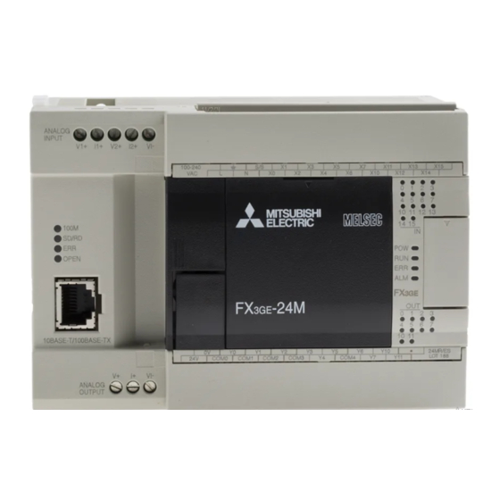
Overview
FX
3GE
PLC has an Ethernet communication function and analog input/output function
built into a base that is FX
3G
PLC.
The Ethernet communication function is equivalent to FX
The analog input/output function (analog input 2 channels, analog output 1 channel) is
equivalent to FX
3U
-3A-ADP.
3G
Series
Associated manuals
How to obtain manuals
For the necessary product manuals or documents, consult with your local Mitsubishi
Electric representative.
Associated manuals
FX
3GE
Series PLC (main unit) comes with this document (hardware manual).
For a detailed explanation of the FX
for PLC programming and special function unit/block, refer to the relevant documents.
Specifications not described in this manual are same as FX
the following manual.
-
3U
→ Refer to FX
Manual name
FX
Series User's Manual
3G
MODEL CODE:
- Hardware Edition
FX
/FX
/FX
/FX
/
3S
3G
3GC
3U
FX
Series
3UC
Programming Manual
MODEL CODE:
- Basic & Applied Instruction
Edition
MELSEC-Q/L/F Structured
Programming Manual
MODEL CODE:
(Fundamentals)
FXCPU Structured
Programming Manual
MODEL CODE:
[Device & Common]
FXCPU Structured
Programming Manual
MODEL CODE:
[Basic & Applied Instruction]
FXCPU Structured
Programming Manual
MODEL CODE:
[Application Functions]
FX Series User's Manual
MODEL CODE:
- Data Communication Edition
FX
/FX
/FX
/FX
/
3S
3G
3GC
3U
FX
Series User's Manual
MODEL CODE:
3UC
- Analog Control Edition
FX
/FX
/FX
/FX
/
3S
3G
3GC
3U
FX
Series User's Manual
MODEL CODE:
3UC
Series User's
3G
- Positioning Control Edition
FX
3U
-ENET-ADP
MODEL CODE:
User's Manual
Certification of UL, cUL standards
Please consult with Mitsubishi Electric for information on UL, cUL standard practices
and the corresponding types of equipment.
Compliance with EC directive (CE Marking)
Series User's Manual -
3G
This product complies with EC directive, however, this document does not guarantee
that a mechanical system including this product will comply with the following
standards.
Compliance to EMC directive and LVD directive of the entire mechanical system should
be checked by the user/manufacturer. For more details please contact the local
Mitsubishi Electric sales site.
Requirement for Compliance with EMC directive
The following products have shown compliance through direct testing (of the identified
-ENET-ADP.
3U
standards below) and design analysis (through the creation of a technical construction
file) to the European Directive for Electromagnetic Compatibility (2014/30/EU) when
used as directed by the appropriate documentation.
Attention
This product is designed for use in industrial applications.
Type :
Programmable Controller (Open Type Equipment)
Models : MELSEC FX
3GE
series manufactured
from March 1st, 2013
FX
3GE
from June 1st, 2013
FX
3GE
from August 1st, 2013
FX
3GE
FX
3GE
Where indicates: 24, 40
Series hardware and information on instructions
3GE
EN61131-2:2007
Programmable controllers
PLC. For details, refer to
3G
- Equipment requirements and
tests
Series User's Manual - Hardware Edition.
3G
Manual No.
Description
Explains FX
Series PLC
3G
JY997D31301
specification details for I/O,
wiring, installation, and
09R521
maintenance.
JY997D16601
Describes PLC programming for
basic/applied instructions STL/
09R517
SFC programming and devices.
Requirement for Compliance with LVD directive
Programming methods,
The following products have shown compliance through direct testing (of the
SH-080782
specifications, functions, etc.
identified standards below) and design analysis (through the creation of a
required to create structured
technical construction file) to the European Directive for Low Voltage (2014/35/
13JW06
EU) when used as directed by the appropriate documentation.
programs.
Type :
Programmable Controller (Open Type Equipment)
JY997D26001
Devices, parameters, etc.
provided in structured projects of
Models : MELSEC FX
09R925
GX Works2.
from March 1st, 2013
from June 1st, 2013
JY997D34701
Sequence instructions provided
from August 1st, 2013
in structured projects of GX
09R926
Works2.
For the products above,PLCs manufactured
JY997D34801
before February 28th, 2018 are compliant with EN61131-2:2007,
Application functions provided in
PLCs manufactured after March 1st, 2018 are compliant with EN61010-2-
structured projects of GX Works2.
09R927
*1
201:2013.
Explains N:N link, parallel link,
JY997D16901
computer link, no protocol
communication by RS
EN61131-2:2007
09R715
instructions/FX
-232IF.
Programmable controllers
2N
- Equipment requirements and tests
Describes specifications for
JY997D16701
analog control and programming
EN61010-2-201:2013
methods for FX
3S
/FX
3G
/FX
3GC
/
09R619
Safety of electrical equipment for
FX
3U
/FX
3UC
Series PLC.
measurement,control,and test
Explains the specifications for
JY997D16801
positioning control of FX
/FX
/
3S
3G
FX
3GC
/FX
3U
/FX
3UC
Series and
09R620
programming procedures
*1 For some models, PLCs manufactured after January 1st, 2018 are
compliant.
JY997D45801
Describes FX
-ENET-ADP
3U
Caution for compliance with EC Directive
Ethernet communication special
09R725
adapter details.
• Please use the FX
conductive shielded control boxes.
• Please secure the control box lid to the control box (for conduction).
Installation within a control box greatly affects the safety of the system and aids
in shielding noise from the programmable controller.
• For the control panel, use the product having sufficient strength, fire
protectiveness and shielding property to an installation environment.
Caution for compliance with the LVD directive (EN61010-2-201:2013)
• To an external connection port other than AC power supply terminal and AC
input/output terminal, connect the circuit separated from a dangerous voltage
by a double/reinforced insulation.
• Between the commons having the adjacent relay output terminals, if an
external power supply is higher than 120 V AC, the insulation is basic.
Therefore, when using 120 V AC or higher external power supply and 30 V DC/
AC or lower external power supply between the adjacent commons, do not
handle 30 V DC/AC or lower external power supply as a touchable part, (When
handling 30 V DC/AC or lower external power supply as a touchable part, add
a basic insulation.)
• Do not wire two or more crimp terminals to one terminal. (If the wiring with two
or more wires is needed,take an appropriate action such as adding an external
terminal.)
• For crimp terminals to be used for the wiring applied with 30 V AC or higher,
use the products with insulating sleeves.
• Cutoff device such as a breaker or a circuit protector should be installed in
accordance with the following precautions.
- Use EN60947-1 or EN60947-3 standards.
-MR/ES
- Place the cutoff device so that it can be operated easily.
-MT/ES
FX
3GE
-MT/ESS
- Specify that the cutoff device is for this equipment.
-MR/DS
FX
3GE
-MT/DS
*2 For the time of compliance with the LVD directive (EN61010-2-201:2013),
-MT/DSS
refer to FX3G Series User's Manual - Hardware Edition.
Standard
Remark
Compliance with all relevant aspects of
the standard.
EMI
• Radiated Emission
• Conducted Emission
EMS
• Radiated electromagnetic field
• Fast transient burst
• Electrostatic discharge
• High-energy surge
• Voltage drops and interruptions
• Conducted RF
• Power frequency magnetic field
3GE
series manufactured
FX
3GE
-MR/ES
FX
3GE
-MT/ES
FX
3GE
-MT/ESS
FX
3GE
-MR/DS
Where indicates: 24, 40
Standard
Remark
The equipment has been assessed
as a component for fitting in a
suitable control box which meets the
requirements of EN61131-2:2007
The equipment has been assessed
as a component for fitting in a
suitable control box which meets the
requirements of EN61010-2-
201:2013
Series programmable controllers while installed in
3GE
*2
Advertisement
Table of Contents

Related Manuals for Mitsubishi Electric FX3GE-24M series


Summary of Contents for Mitsubishi Electric FX3GE-24M series
- Page 1 • For the control panel, use the product having sufficient strength, fire Please consult with Mitsubishi Electric for information on UL, cUL standard practices • The PLC is a precision instrument. During transportation, avoid impacts larger protectiveness and shielding property to an installation environment.
- Page 2 10BASE-T/100BASE-TX connector (RJ45) these users should follow those manufacturers' installation requirements. - 40 point I/O type cannot use the BD1 slot. Mitsubishi Electric recommends that shielded cables be used. If NO other EMC - FX -CNV-ADP, FX -ENET-ADP cannot be connected.
-
Page 3: Installation Precautions
3.2 Installation location Built-in Ethernet part *2 Dielectric withstand voltage and insulation resistance are shown in the following INSTALLATION table. PRECAUTIONS Install the PLC in an environment conforming to the generic specifications (section Status Description display color Insulation 3.1), installation precautions and notes. •... -
Page 4: Design Precautions
3.3 Procedures for installing to and detaching from DIN rail 4.2 Power supply specifications and example of external Notes 4. Power supply/input/output specifications and external wiring The products can be installed on a DIN46277 rail [35mm (1.38”) wide]. wiring example of the main unit part •... -
Page 5: Specification
JY997D49401H 4.2.3 Example of external wiring (DC power type) 4.4 Input specifications and external wiring 4.4.3 Examples of input wiring [DC power type] 4.5 Relay output specifications and example of external wiring 24V DC power is supplied to the main unit and input/output extension unit. As for the details of the input specifications of I/O extension unit/block and external 1.Sink input type 2.Source input type... - Page 6 • Do not disassemble or modify this product. Doing so may cause fire, equipment failures, or malfunctions. For repair, contact your local Mitsubishi Electric representative. • The adapter case is made of resin. If dropped or subjected to strong impact, the adapter may be damaged.
- Page 7 3) Termination Failure to do so may cause fire, equipment failures or malfunctions. For repair, contact your local Mitsubishi Electric representative. Strip the coating of strand wire and twist the cable core before connecting it, • Make sure to observe the following precautions in order to prevent any + side of receiving data •...
-
Page 8: For Safe Use
• - Analog Control Edition. The grounding resistance should be 100Ω or less. nor does it confer any patent licenses. Mitsubishi Electric Corporation cannot be resistance is 2kΩ. resistance is 250Ω. held responsible for any problems involving industrial property rights which may occur as a result of using the contents noted in this manual. -
Page 9: Safety Precautions
• For the control panel, use the product having sufficient strength, fire Please consult with Mitsubishi Electric for information on UL, cUL standard practices • The PLC is a precision instrument. During transportation, avoid impacts larger protectiveness and shielding property to an installation environment. - Page 10 Built-in Ethernet part *2 Dielectric withstand voltage and insulation resistance are shown in the following 3.2 Installation location INSTALLATION table. PRECAUTIONS Install the PLC in an environment conforming to the generic specifications (section Status Description display color Insulation 3.1), installation precautions and notes. •...
- Page 11 • Do not disassemble or modify this product. Doing so may cause fire, equipment failures, or malfunctions. For repair, contact your local Mitsubishi Electric representative. • The adapter case is made of resin. If dropped or subjected to strong impact, the adapter may be damaged.
- Page 12 • - Analog Control Edition. The grounding resistance should be 100Ω or less. nor does it confer any patent licenses. Mitsubishi Electric Corporation cannot be resistance is 2kΩ. resistance is 250Ω. held responsible for any problems involving industrial property rights which may occur as a result of using the contents noted in this manual.