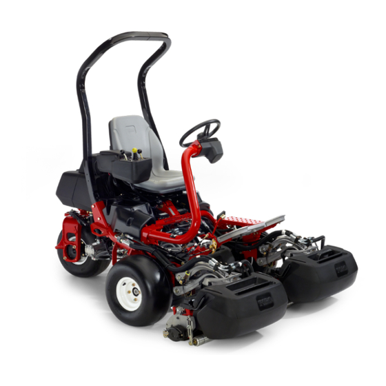
Toro Greensmaster TriFlex 3300 Operator's Manual
Traction unit
Hide thumbs
Also See for Greensmaster TriFlex 3300:
- Manual (334 pages) ,
- Service manual (332 pages) ,
- Operator's manual (52 pages)

Related Manuals for Toro Greensmaster TriFlex 3300


Summary of Contents for Toro Greensmaster TriFlex 3300
- Page 1 Form No. 3419-302 Rev A Greensmaster ® 3300 TriFlex ® Traction Unit Model No. 04510—Serial No. 401390001 and Up *3419-302* A Register at www.Toro.com. Original Instructions (EN)
- Page 2 For more information on safe operating practices, including safety tips and training materials, go to www.Toro.com. Whenever you need service, genuine Toro parts, or additional information, contact an Authorized Toro Distributor and have the model and serial numbers of your product ready.
-
Page 3: Table Of Contents
Contents Locating the Fuses ........... 34 Drive System Maintenance ........34 Checking the Tire Pressure....... 34 Safety ............... 4 Checking the Torque of the Wheel General Safety ........... 4 Nuts .............. 34 Safety and Instructional Decals ......4 Adjusting the Transmission for Neutral....34 Setup ................ -
Page 4: Safety
Safety • Do not operate the machine without all guards and other safety protective devices in place and working on the machine. This machine has been designed in accordance • Keep clear of any discharge opening. Keep with EN ISO 5395:2013 and ANSI B71.4-2017 bystanders and pets a safe distance away from and meets these standards when you add the the machine. - Page 5 decal117-2718 117–2718 decal119-9346 119-9346 1. Press the pedal to unlock. 2. Read the Operator's Manual for more information. decal115-8226 115-8226 1. Tipping hazard—read the Operator's Manual; always wear a seat belt when operating; do not remove the rollover protection system (ROPS).
- Page 6 decal132-9548 132-9548 1. Engine speed—fast 7. Reel speed—neutral 2. Engine speed—slow 8. Reel—transport 3. Lower and engage the reels 9. Reel—mow 4. Raise and disengage the reels 10. Reel—backlaping 5. Reel speed—fast 11. Move forward 6. Reel speed—slow decal132-9549 132-9549 1.
- Page 7 decalbatterysymbols Battery Symbols decal131-2046 Some or all of these symbols are on your battery. 131-2046 1. Explosion hazard 6. Keep bystanders a safe 1. Double lights 3. Off distance away from the 2. Single light battery. 2. No fire, open flame, or 7.
- Page 8 decal115-8156 115-8156 1. Reel height 3. 8–Blade cutting unit 5. 14–Blade cutting unit 7. Fast 2. 5–Blade cutting unit 4. 11–Blade cutting unit 6. Reel speed 8. Slow decal119-9345 119-9345...
-
Page 9: Setup
Grass-basket hook Install the grass-basket hooks. Flange bolts Gauge bar Cutting unit (obtain from your authorized Install the cutting units. Toro Distributor) Grass basket Weight kit (Part No. 119-7129)—sold Add rear weight. separately Warning decal (Part No. 136-8505) Install the CE decals, if required. -
Page 10: Installing The Roll Bar
Installing the Roll Bar Installing the Seat Parts needed for this procedure: Parts needed for this procedure: Seat Roll bar Seat wire harness Bolt (1/2 x 3-3/4 inches) Flange nut (1/2 inch) Procedure Procedure Note: Mount the seat in the front set of mounting holes to gain an additional 7.6 cm (3 inches) in the Remove the top crate support from the crate. -
Page 11: Installing The Steering Wheel
seat moves, and connect it to the port on the bottom of the seat. Activating and Charging the Battery Installing the Steering Wheel No Parts Required Procedure Parts needed for this procedure: Use only electrolyte (1.265 specific gravity) to fill the Steering wheel battery initially. - Page 12 When the battery is charged, disconnect the charger from the electrical outlet and battery posts. Note: After the battery has been activated, add only distilled water to replace normal loss, although maintenance-free batteries should not require water under normal operating conditions. Important: Failure to correctly activate the battery may result in battery gassing and/or...
-
Page 13: Installing The Oil Cooler
(Part No. 119-1691). Installing the Cutting Units Parts needed for this procedure: Installing the Grass-Basket Gauge bar Hooks Cutting unit (obtain from your authorized Toro Distributor) Grass basket Parts needed for this procedure: Grass-basket hook Procedure Flange bolts Prepare the cutting units for installation;... -
Page 14: Adding Rear Weight
Adding Rear Weight Reducing the Tire Pressure Parts needed for this procedure: No Parts Required Weight kit (Part No. 119-7129)—sold separately Procedure Procedure The tires are overinflated at the factory for shipping purposes. Reduce the pressure to the proper levels This machine complies with ANSI B71.4-2017 and before starting the machine;... -
Page 15: Product Overview
Product Overview g014603 Figure 12 1. Traction pedal—forward 3. Steering-arm-locking pedal 2. Taction pedal—reverse g014674 Figure 11 1. Engine 5. Steering wheel 2. Roll bar 6. Traction pedal 3. Control panel 7. Footrest 4. Seat 8. Cutting units Controls g005105 Traction Pedal Figure 13 The traction pedal... - Page 16 Ignition Switch Insert the key into the switch (Figure 14) and turn it clockwise to the S position to start the engine. TART Release the key as soon as the engine starts; the key moves to the O position. Turn the key counterclockwise to the S position to shut off the engine.
- Page 17 in conjunction with the raise/lower mow control lever and the reel-speed control for backlapping the reels. g014620 Figure 17 1. Backlap lever—mow 2. Backlap lever—backlap position position g014600 Reel-Speed Control Figure 15 1. Hour meter The reel-speed control is located under the plastic cover to the left of the seat.
-
Page 18: Specifications
Contact your Fuel-Shutoff Valve Authorized Service Dealer or Distributor or go to www.Toro.com for a list of all approved attachments Close the fuel-shutoff valve (Figure 20), behind and accessories. -
Page 19: Before Operation
Operation Recommended Fuel: Unleaded gasoline with an octane rating of 87 or higher ((R+M)/2 rating method) Ethanol: Gasoline with up to 10% ethanol (gasohol) Note: Determine the left and right sides of the or 15% MTBE (methyl tertiary butyl ether) by volume machine from the normal operating position. -
Page 20: Performing Daily Maintenance
During Operation During Operation Safety General Safety • The owner/operator can prevent and is responsible for accidents that may cause personal injury or property damage. • Wear appropriate clothing, including eye protection; long pants; slip-resistant, substantial foot protection; and hearing protection. Tie back long hair and do not wear jewelry. -
Page 21: Breaking In The Machine
• Use accessories, attachments, and replacement – Use extreme caution when operating parts approved by The Toro® Company only. the machine near drop-offs, ditches, embankments, water hazards, or other Rollover Protection System hazards. The machine could suddenly roll over... -
Page 22: Starting The Engine
Starting the Engine Note: If fluid leaks continue to appear, contact your authorized Toro distributor for assistance Note: Inspect the areas beneath the cutting units to and, if necessary, replacement parts. ensure that they are clear of debris. Important: A trace of fluid on the motor or Sit on the seat, engage the parking brake, wheel seals is normal. -
Page 23: Driving The Machine Without Mowing
Checking the Traction Pedal Checking the Raise/Lower Mow Control Perform the following system checks daily to ensure that the interlock system is operating correctly: Sit on the seat, move the traction pedal to the position, move the functional control EUTRAL Sit on the seat, move the traction pedal to the lever to the N position, and engage the... - Page 24 Cutting the Green Approach the green with the functional-control lever in the M position and the throttle at full speed. Start on 1 edge of the green so that you can use the ribbon procedure of cutting. Note: This holds compaction to a minimum and leaves a neat, attractive pattern on the greens.
-
Page 25: After Operation
Cutting the Periphery and • Inspect the machine for possible hydraulic fluid leaks, damage or wear to hydraulic and Finishing Job mechanical components. Finish cutting the green by mowing the outer • Inspect the cutting units for sharpness. periphery. Change the direction of cutting from •... -
Page 26: Towing The Machine
Towing the Machine In case of an emergency, you can tow the machine for up to 0.4 km (1/4 mile). Important: Do not tow the machine faster than 3 to 5 km/h (2 to 3 mph) to avoid damaging the drive system. -
Page 27: Maintenance
Determine the left and right sides of the machine from the normal operating position. Note: Download a free copy of the electrical or hydraulic schematic by visiting www.Toro.com and searching for your machine from the Manuals link on the home page. -
Page 28: Recommended Maintenance Schedule(S)
Recommended Maintenance Schedule(s) Maintenance Service Maintenance Procedure Interval • Torque the wheel nuts. After the first hour • Torque the wheel nuts. After the first 10 hours • Change the engine oil and filter. After the first 25 hours • Change the hydraulic-fluid filter. After the first 50 hours •... -
Page 29: Daily Maintenance Checklist
Daily Maintenance Checklist Duplicate this page for routine use. Maintenance Check Item For the week of: Mon. Tues. Wed. Thurs. Fri. Sat. Sun. Check the safety-interlock operation. Check the instrument operation Check the leak-detector alarm. Check the brake operation. Check the fuel level. Check the hydraulic-fluid level. -
Page 30: Pre-Maintenance Procedures
Pre-Maintenance Engine Maintenance Procedures Engine Safety Pre-Maintenance Safety • Shut off the engine before checking the oil or adding oil to the crankcase. • Before adjusting, cleaning, repairing, or leaving • Do not change the governor speed or overspeed the machine, do the following: the engine. -
Page 31: Servicing The Engine Oil
g005111 Figure 28 1. Dipstick 2. Filler cap g005126 Figure 27 1. Foam element 2. Paper element Unscrew the dipstick, pull it out of the tube, and check the oil level. Check the condition of the paper element. Clean If the oil level is low, remove the filler cap from it by gently tapping it on a flat surface or replace the valve cover and add oil into the engine it if needed. -
Page 32: Replacing The Spark Plugs
Fuel System Clean the threads of the drain plug, apply PTFE sealant, and install the drain plug (Figure 29). Maintenance Remove the oil filter (Figure 29). Apply a light coat of clean oil to the new filter gasket. Replacing the Fuel Filter Screw the filter on by hand until the gasket Service Interval: Every 800 hours (sooner if the fuel contacts the filter adapter, then tighten it 3/4 to 1... -
Page 33: Electrical System Maintenance
Electrical System If needed, add distilled or demineralized water into the cell of the battery. Maintenance Note: Raise the electrolyte level only to the bottom of the split ring inside each cell. Electrical System Safety Clean the top of the battery by washing it periodically with a brush dipped in ammonia or •... -
Page 34: Locating The Fuses
Locating the Fuses Drive System Maintenance The fuses in the electrical system are located under the seat (Figure 32). Checking the Tire Pressure Service Interval: Before each use or daily Vary the tire pressure for all 3 wheels, depending upon your turf conditions, from a minimum of 83 to a maximum of 110 kPa (12 psi to 16 psi). -
Page 35: Adjusting The Transport Speed
Important: Ensure that the tension on the eccentric is at the maximum adjustment, cable is not excessive or you will reduce the contact your authorized Toro distributor cable life. or refer to the Service Manual for further adjustment. Reducing the Transport Speed... -
Page 36: Brake Maintenance
Brake Maintenance Adjusting the Brakes If the brake fails to hold the machine while parked, you can adjust the brakes using the bulkhead fitting near the brake drum; contact your Authorized Service Distributor or refer to the Service Manual for more information. -
Page 37: Hydraulic System Maintenance
Toro distributor for part numbers.) The hydraulic-fluid reservoir is filled at the factory Alternate fluids: If the Toro fluid is not available, other with high quality hydraulic fluid. Before operating the fluids may be used provided they meet all the following machine each day, check the level of the hydraulic material properties and industry specifications. - Page 38 Check the fluid level according to the tank on your machine: • If your machine has a fuel gauge at the top of the fuel tank, locate the dipstick for the hydraulic system at the top of the leak detector tank (Figure 36) and proceed to step 3.
-
Page 39: Checking The Hydraulic Lines And Hoses
If the fluid becomes contaminated, have your • Ensure that all hydraulic fluid hoses authorized Toro distributor flush the system. and lines are in good condition and all Contaminated fluid looks milky or black when hydraulic connections and fittings are tight compared to clean fluid. - Page 40 g229110 g229108 Figure 41 Figure 39 Leak Alert! Before Starting (fluid cold) 1. Float switch 3. Fluid level (warm) 1. Filler plug 5. Warning buzzer—no (down—closed) sound Fluid level down 118 2. Filler neck 6. Fluid level (cold) to 177 ml (4 to 6 oz) 3.
-
Page 41: Cutting Unit Maintenance
Cutting Unit Maintenance Cutting Unit Safety A worn or damaged blade or bed-knife can break, and a piece could be thrown at you or bystanders, resulting in serious personal injury or death. • Inspect the blades and bed-knives periodically for excessive wear or damage. - Page 42 g014609 Figure 45 1. Latch—closed position 3. Latch—open position g014596 Figure 43 2. Suspension-arm bar 2. Bedbar-adjusting-screw 1. Prop (not provided) nut (2) Installing the Cutting Units Lift up on the footrest and swing it open, allowing access to the center cutting unit position (Figure 44).
- Page 43 g014605 Figure 48 1. Reel motor 2. Motor-retaining bar Move the motor to the storage location on the front of the suspension arm (Figure 49). g014690 Figure 47 g014608 Figure 49 1. Reel motor 3. Cavity 2. Spline shaft 4. Motor-retaining bar Note: When sharpening, setting the height-of-cut, or performing other maintenance...
-
Page 44: Checking The Reel-To-Bedknife Contact
Checking the Reel-to-Bedknife Contact Each day before operating the machine, check the reel-to-bedknife contact, regardless if the quality of cut had previously been acceptable. There must be light contact across the full length of the reel and bedknife; refer to the Cutting Unit Operator’s Manual. Setting the Reel Speed To achieve a consistent, high-quality cut and a uniform, after-cut appearance, you must correctly set... - Page 45 Rotate the backlap lever to the R Repeat the procedure for all cutting units you EVERSE position (Figure 52). want to backlap. When finished, return the backlap levers to the (F) position, replace the cover, and ORWARD wash all lapping compound off of the cutting units.
-
Page 46: Diagnostics System
Diagnostics System Note: The system stores only the 3 most recent fault codes. For a list of error codes, refer to your authorized Toro Diagnosing the Service distributor or the Service Manual. Indicator Light The service indicator light illuminates in the event of a fault in the machine. -
Page 47: Storage
Storage If you wish to store the machine for a long period of time, the perform following steps: Remove accumulations of dirt and old grass clippings. Sharpen the reels and bedknives, if necessary; refer to the cutting unit Operator's Manual. Coat the bedknives and reel blades with a rust preventive. - Page 48 Notes:...
- Page 49 Notes:...
- Page 50 Notes:...
- Page 51 The Way Toro Uses Information Toro may use your personal information to process warranty claims, to contact you in the event of a product recall and for any other purpose which we tell you about. Toro may share your information with Toro's affiliates, dealers or other business partners in connection with any of these activities. We will not sell your personal information to any other company.
- Page 52 Countries Other than the United States or Canada Customers who have purchased Toro products exported from the United States or Canada should contact their Toro Distributor (Dealer) to obtain guarantee policies for your country, province, or state. If for any reason you are dissatisfied with your Distributor's service or have difficulty obtaining guarantee information, contact the Toro importer.