Toro Greensmaster TriFlex 3300 Service Manual
Hide thumbs
Also See for Greensmaster TriFlex 3300:
- Manual (334 pages) ,
- Operator's manual (52 pages) ,
- Operator's manual (44 pages)
Table of Contents
Advertisement
Quick Links
Download this manual
See also:
Operator's Manual
Greensmaster
Preface
The purpose of this publication is to provide the service
technician with information for troubleshooting, testing
and repair of major systems and components on the
Greensmaster TriFlex 3300 and 3400.
REFER TO THE TRACTION UNIT AND CUTTING
UNIT OPERATOR'S MANUALS FOR OPERATING,
MAINTENANCE AND ADJUSTMENT INSTRUC-
TIONS. For reference, insert a copy of the Operator's
Manuals and Parts Catalogs for your machine into
Chapter 2 of this service manual. Additional copies of
the Operator's Manuals and Parts Catalog are available
on the internet at www.Toro.com.
The Toro Company reserves the right to change product
specifications or this publication without notice.
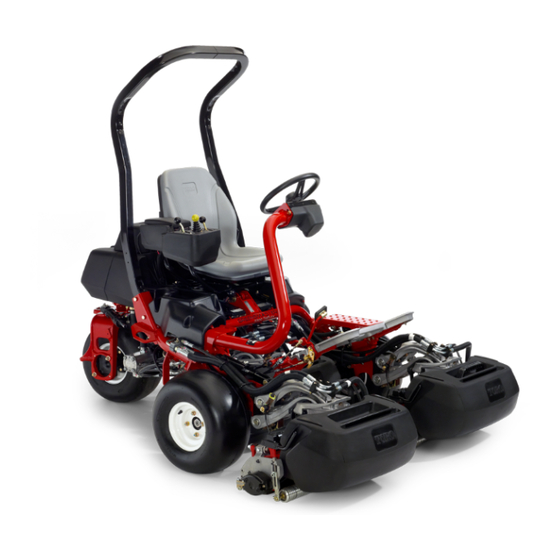
Greensmaster 3300
E The Toro Company - - 2012
(Models 04510 and 04520)
R
TM
TriFlex
This safety symbol means DANGER, WARNING
or CAUTION, PERSONAL SAFETY INSTRUC-
TION. When you see this symbol, carefully read
the instructions that follow. Failure to obey the
instructions may result in personal injury.
NOTE: A NOTE will give general information about the
correct operation, maintenance, service, testing or re-
pair of the machine.
IMPORTANT: The IMPORTANT notice will give im-
portant instructions which must be followed to pre-
vent damage to systems or components on the
machine.
Part No. 12187SL
Service Manual
3300/3400
Advertisement
Chapters
Table of Contents
Troubleshooting

Related Manuals for Toro Greensmaster TriFlex 3300


Summary of Contents for Toro Greensmaster TriFlex 3300
-
Page 1: Service Manual
The Toro Company reserves the right to change product IMPORTANT: The IMPORTANT notice will give im- specifications or this publication without notice. portant instructions which must be followed to pre- vent damage to systems or components on the machine. - Page 2 This page is intentionally blank. Greensmaster 3300/3400...
-
Page 3: Table Of Contents
Table Of Contents Chapter 1 - - Safety Chapter 6 - - Electrical System General Safety Instructions ....1 -- 2 General Information . - Page 4 This page is intentionally blank. Greensmaster 3300/3400...
- Page 5 Table Of Contents (Continued) Chapter 9 - - Groomer Specifications ......9 -- 2 General Information .
- Page 6 This page is intentionally blank. Greensmaster 3300/3400...
-
Page 7: General Safety Instructions 1
Chapter 1 Safety Table of Contents GENERAL SAFETY INSTRUCTIONS ... . Before Operating ......While Operating . -
Page 8: General Safety Instructions
General Safety Instructions Greensmaster TriFlex 3300 and 3400 machines have been tested and certified by TORO for compliance with WARNING existing safety standards and specifications. Although hazard control and accident prevention partially are de- To reduce the potential for injury or death, pendent upon the design and configuration of the ma- comply with the following safety instructions. -
Page 9: While Operating
Machine must not move. If movement is evident, the traction pedal linkage is E. Toro recommends that anytime the machine is adjusted incorrectly; therefore, shut engine off and parked (short or long term), the cutting units should adjust traction pedal linkage until machine does not be lowered to the ground. -
Page 10: Maintenance And Service
Toro replacement parts and accessories. Replacement parts and accessories made 7. Before disconnecting or performing any work on the... -
Page 11: Jacking Instructions
Jacking Instructions CAUTION When changing attachments, tires or perform- ing other service, use correct jacks and sup- ports. Make sure machine is parked on a solid, level surface such as a concrete floor. Prior to raising machine, remove any attachments that may interfere with the safe and proper raising of the machine. -
Page 12: Safety And Instruction Decals
TriFlex 3300 and 3400 machines. If any decal becomes illegible or damaged, install a new decal. Part numbers are listed in your Parts Catalog and Operator’s Manual. Order replacement decals from your Authorized Toro Distributor. Safety Page 1 - - 6... -
Page 13: Product Records
Chapter 2 Product Records and Maintenance Table of Contents PRODUCT RECORDS ......MAINTENANCE ....... EQUIVALENTS AND CONVERSIONS . -
Page 14: Equivalents And Conversions
Equivalents and Conversions 0.09375 Product Records and Maintenance Page 2 - - 2 Greensmaster 3300/3400... -
Page 15: Torque Specifications
For critical applications, as determined reduced by 25% for lubricated fasteners to achieve by Toro, either the recommended torque or a torque that the similar stress as a dry fastener. Torque values may is unique to the application is clearly identified and spe- also have to be reduced when the fastener is threaded cified in this Service Manual. - Page 16 Standard Torque for Dry, Zinc Plated and Steel Fasteners (Inch Series) Grade 1, 5 & SAE Grade 1 Bolts, Screws, Studs & SAE Grade 5 Bolts, Screws, Studs & SAE Grade 8 Bolts, Screws, Studs & Thread Size 8 with Thin Sems with Regular Height Nuts Sems with Regular Height Nuts Sems with Regular Height Nuts...
- Page 17 Standard Torque for Dry, Zinc Plated and Steel Fasteners (Metric Fasteners) Class 8.8 Bolts, Screws and Studs with Class 10.9 Bolts, Screws and Studs with Thread Size Thread Size Regular Height Nuts Regular Height Nuts Regular Height Nuts Regular Height Nuts (Class 8 or Stronger Nuts) (Class 10 or Stronger Nuts) M5 X 0.8...
- Page 18 Other Torque Specifications SAE Grade 8 Steel Set Screws Wheel Bolts and Lug Nuts Recommended Torque Thread Size Recommended Torque** Thread Size Thread Size Square Head Hex Socket 7/16 -- 20 UNF 65 + 10 ft--lb 88 + 14 N--m Grade 5 1/4 -- 20 UNC 140 + 20 in--lb...
-
Page 19: General Information 3
Chapter 3 Gasoline Engine Table of Contents SPECIFICATIONS ......GENERAL INFORMATION ..... Operator’s Manual . -
Page 20: Specifications
Specifications Item Description Make / Designation Briggs and Stratton, 4--cycle, V--Twin Cylinder, OHV, Air Cooled, Gasoline Engine -- Model 385447 Bore x Stroke 2.97” x 2.76” (75.5 mm x 70 mm) Total Displacement 38.3 in (627 cc) Governor Mechanical Governor Carburetor Float Feed, Two Barrel Fuel Pump... -
Page 21: General Information
V-Twin OHV engines are supplied through your local lo- in the Greensmaster TriFlex 3300 is included in this cal Toro distributor. If no parts list is available, be sure to chapter and the Briggs & Stratton Vanguard V--Twin provide your distributor with the Toro model and serial OHV Repair Manual. -
Page 22: Fuel Evaporative Control System
Fuel Evaporative Control System SERIAL NUMBER BELOW 312000000 CHECK VALVE TO INTAKE FUEL MANIFOLD TANK CARBON CANNISTER ENGINE FRESH AIR FILTER SERIAL NUMBER ABOVE 312000000 CHECK CARBON VALVE CANNISTER TO INTAKE MANIFOLD FUEL TANK CHECK FRESH AIR VALVE FILTER TO AIR CLEANER ENGINE Figure 1... - Page 23 The function of the fuel evaporative control system is to Machines With Serial Number Below 312000000 collect and store evaporative emissions from the fuel On machines with serial number below 312000000, the tank and engine. The evaporate control system used on carbon canister is mounted under the fuel tank mount Greensmaster 3300 machines uses a carbon cannister plate.
- Page 24 This page is intentionally blank. Gasoline Engine Page 3 - - 6 Greensmaster 3300...
-
Page 25: Adjustments
Adjustments Choke Cable Adjustment 1. Park machine on a level surface, disengage and low- 4. If cable adjustment is needed, loosen cap screw and er cutting units, move functional control lever to neutral nut that secure choke cable clamp. Reposition cable to (N), engage parking brake, stop the engine and remove allow correct choke operation. -
Page 26: Service And Repairs
Service and Repairs Fuel Evaporative Control System (Serial Number Below 312000000) RIGHT FRONT Figure 3 1. Flange head screw (2 used) 8. Bracket 14. Washer head screw 2. Tank mount plate 9. Flange nut (2 used) 15. Check valve 3. Fuel hose (to engine intake manifold) 10. - Page 27 Removal (Fig. 3) 1. Park machine on a level surface, disengage and low- er cutting units, move functional control lever to neutral (N), engage parking brake, stop the engine and remove the key from the ignition switch. Wait for all machine movement to stop.
-
Page 28: Fuel Evaporative Control System (Serial Number Above 312000000)
Fuel Evaporative Control System (Serial Number Above 312000000) RIGHT FRONT Figure 5 1. Flange head screw (2 used) 13. Fuel hose (fuel supply) 25. Flat washer (3 used) 2. Tank mount plate 14. Hose clamp (5 used) 26. Flange head screw (2 used) 3. - Page 29 Removal (Fig. 5) Installation (Fig. 5) 1. Park machine on a level surface, disengage and low- 1. Install all removed components using Figure 5 as a er cutting units, move functional control lever to neutral guide. (N), engage parking brake, stop the engine and remove A.
-
Page 30: Fuel Tank
Fuel Tank Illustration from machine with serial number below 312000000 shown Antiseize Lubricant 30 to 50 in- -lb (3.4 to 5.6 N- -m) RIGHT FRONT Figure 7 1. Flange head screw (2 used) 13. Fuel supply hose 25. Flat washer (2 used) 2. - Page 31 Fuel Tank Removal (Fig. 7) Fuel Tank Installation (Fig. 7) 1. Park machine on a level surface, disengage and low- 1. Install fitting assembly and shut--off valve into fuel er cutting units, move functional control lever to neutral tank if they were removed from tank (Fig. 8). The nut and (N), engage parking brake, stop the engine and remove fitting have left hand threads.
-
Page 32: Engine
Engine 90 to 110 in- -lb (10.2 to 12.4 N- -m) FRONT 20 to 25 in- -lb (2.3 to 2.8 N- -m) Antiseize RIGHT Lubricant 25 to 38 ft- -lb (34 to 51 N- -m) 170 to 200 in- -lb (19.3 to 22.6 N- -m) Figure 9 1. - Page 33 2. Disconnect the negative (--) battery cable at the bat- tery. 3. Close fuel shut--off valve on fuel tank. 4. Disconnect fuel hoses from the fuel filter outlet and the check valve near rear engine cylinder head (Fig. 10). Drain any fuel trapped in the fuel filter and fuel hose into a suitable container.
-
Page 34: Engine Installation
Engine Installation (Fig. 9) 7. Secure wire harness ground connector to engine as- sembly with cap screw (item 5), flat washer (item 26), 1. Make sure that all removed engine components are lock washer (item 25) and flange nut (item 6) (Fig. 11). correctly installed to the engine. -
Page 35: Specifications
Chapter 4 Diesel Engine Table of Contents SPECIFICATIONS ......GENERAL INFORMATION ..... Operator’s Manual . -
Page 36: Specifications
Specifications Item Description Make / Designation Kubota water--cooled, Diesel, Model D902--E3B Number of Cylinders Bore x Stroke 2.83” x 2.9” (72mm x 73.6mm) Total Displacement 54.8 in (898 cc) Compression Ratio 24.0:1 Firing Order 1 (closest to gear case end) -- 2 -- 3 (closest to flywheel end) Direction of Rotation Counterclockwise (viewed from flywheel) Fuel... -
Page 37: General Information
Service and repair parts for Kubota engines are sup- shooting, testing and repair of the diesel engine used in plied through your local local Toro distributor. If no parts the Greensmaster TriFlex 3400 is included in this chap- list is available, be sure to provide your distributor with ter and the Kubota Workshop Manual, Diesel Engine, the Toro model and serial number. - Page 38 This page is intentionally blank. Diesel Engine Page 4 - - 4 Greensmaster 3400...
-
Page 39: Adjust Throttle Control
Adjustments Adjust Throttle Control Proper throttle operation is dependent upon proper ad- justment of throttle control. Make sure throttle control is operating properly. NOTE: The throttle cable swivel should be positioned in the lowest hole in the speed control lever. 1. -
Page 40: Air Cleaner Assembly
Service and Repairs Air Cleaner Assembly RIGHT FRONT Figure 3 1. Air inlet hood 4. Mounting bracket 7. Flange nut (2 used) 2. Flat washer (2 used) 5. Air cleaner assembly 8. Air intake hose 3. Cap screw (2 used) 6. - Page 41 Air Cleaner Removal (Fig. 3) 1. Park machine on a level surface, lower the cutting units, stop the engine, engage parking brake and re- move the key from the ignition switch. 2. Remove air cleaner components as needed using Figure 3 as a guide. 3.
-
Page 42: Exhaust System
Exhaust System FRONT RIGHT Figure 5 1. Engine assembly 7. Lock washer (3 used) 13. Flat washer (8 used) 2. Muffler assembly 8. Exhaust plate 14. Cap screw (4 used) 3. Lock nut (4 used) 9. Exhaust gasket 15. Brace 4. - Page 43 Exhaust System Removal (Fig. 5) Exhaust System Installation (Fig. 5) 1. Park machine on a level surface, lower the cutting 1. Make sure the engine is off. units, stop the engine, engage parking brake and re- IMPORTANT: If exhaust studs were removed from move the key from the ignition switch.
-
Page 44: Fuel Tank
Fuel Tank Antiseize Lubricant RIGHT 30 to 50 in- -lb (3.4 to 5.6 N- -m) FRONT Figure 6 1. Fuel tank 7. Grommet 13. Flat washer (4 used) 2. Tank mount plate 8. Bushing 14. Cap screw (4 used) 3. Flange head screw (4 used) 9. - Page 45 2. Position fuel tank on the tank mount plate. DANGER 3. Move fuel tank towards the rear of the machine and install return hose (item 15) to elbow fitting on front of tank. Secure hose with hose clamp. Diesel fuel is flammable. Use caution when stor- ing or handling it.
-
Page 46: Radiator
Radiator RIGHT FRONT Figure 8 1. Seal panel 10. Stud retainer (2 used) 18. Flange head screw (4 used) 2. Radiator shroud 11. Receptacle (2 used) 19. Front shroud 3. Trim seal 12. Cap screw (4 used) 20. Flange nut (12 used) 4. - Page 47 Radiator Removal (Fig. 8) 10.Disconnect fan wire connector from machine wire harness. 1. Park machine on a level surface, lower the cutting units, stop the engine, engage parking brake and re- 11. Support radiator assembly to prevent it from falling. move the key from the ignition switch.
-
Page 48: Engine
Engine FRONT RIGHT Figure 9 1. Engine assembly 11. Flange nut 20. V- -belt 2. Muffler assembly 12. Brace 21. Fuel/water separator 3. Lock nut (4 used) 13. Flat washer (8 used) 22. Cap screw (2 used) 4. Exhaust pipe 14. - Page 49 2. Close fuel shut--off valve on fuel tank. 3. Remove air cleaner and air intake hose from ma- chine (see Air Cleaner Removal in this section). 4. Remove radiator from machine (see Radiator Re- moval in this section). 5. Remove exhaust system from machine (see Ex- haust System Removal in this section).
-
Page 50: Engine Installation
CAUTION When removing engine assembly, make sure lift or hoist can safely support 190 lbs (86 kg). 11. Attach a suitable lift or hoist to engine. Support en- gine with lift or hoist to prevent engine from shifting or moving. 12.Remove fasteners that secure engine to machine: A. - Page 51 IMPORTANT: Make sure to not damage the engine, 13.Insert fuel supply hose and fuel return hose through fuel hoses, hydraulic lines, electrical harness or grommets in engine support on front of engine. Remove other parts while installing the engine. Also, make plugs placed during engine removal from hoses.
-
Page 52: Engine Bell Housing
Engine Bell Housing FRONT RIGHT Figure 17 1. Engine 3. Bell housing 5. Flange head screw (5 used) 2. Flange head screw (5 used) 4. Coupling flange 6. Dowel pin (2 used) Removal (Fig. 17) Installation (Fig. 17) NOTE: The hydraulic pump assembly needs to be re- 1. -
Page 53: Specifications 5
Chapter 5 Hydraulic System Table of Contents SPECIFICATIONS ......SERVICE AND REPAIRS . - Page 54 This page is intentionally blank. Hydraulic System Page 5 - - 2 Greensmaster 3300/3400...
-
Page 55: Specifications
Specifications Item Description Piston (Traction) Pump Variable displacement piston pump (Eaton model 70160) Maximum Pump Displacement (per revolution) 1.44 in (23.6 cc) Gear Pump 2 section, positive displacement gear pump (Casappa) Front Section Displacement (per revolution) 0.58 in (9.5 cc) Rear Section Displacement (per revolution) 0.33 in (5.4 cc) -
Page 56: General Information
2. Fuel tank Pushing Traction Unit In case of emergency, your Greensmaster can be pushed for a very short distance. However, Toro does not recommend this as a standard procedure. 1. Make sure that engine is not running. 2. Locate by--pass valve on piston (traction) pump (Fig. -
Page 57: Relieving Hydraulic System Pressure
Traction Circuit Component Failure The traction circuit on your Greensmaster machine is a Once the Toro high flow hydraulic filter kit has been closed loop system that includes the piston (traction) placed in the circuit, raise and support the machine with pump and two (2) wheel motors (three (3) wheel motors all drive wheels off the ground. -
Page 58: Hydraulic Hoses
Tube Installation in this section). If the hose has an el- bow at one end, tighten the swivel nut on that end before tightening the nut on the straight end of the hose. For additional hydraulic hose information, refer to Toro Service Training Book, Hydraulic Hose Servicing (Part Number 94813SL). -
Page 59: Hydraulic Hose And Tube Installation
Hydraulic Hose and Tube Installation (O- -Ring Face Seal Fitting) 1. Make sure threads and sealing surfaces of the hose/ C. Use a second wrench to tighten the nut to the cor- tube and the fitting are free of burrs, nicks, scratches or rect Flats From Wrench Resistance (F.F.W.R.). - Page 60 Hydraulic Fitting Installation (SAE Straight Thread O- -Ring Fitting into Component Port) Non- -Adjustable Fitting (Fig. 6) 5. If a torque wrench is not available, or if space at the port prevents use of a torque wrench, an alternate meth- 1.
- Page 61 Adjustable Fitting (Fig. 8) 1. Make sure all threads and sealing surfaces of fitting and component port are free of burrs, nicks, scratches or any foreign material. 2. As a preventative measure against leakage, it is rec- ommended that the O--ring be replaced any time the connection is opened.
-
Page 62: Hydraulic Schematic
Hydraulic Schematic Hydraulic System Page 5 - - 10 Greensmaster 3300/3400... - Page 63 This page is intentionally blank. Greensmaster 3300/3400 Page 5 - - 11 Hydraulic System...
-
Page 64: Hydraulic Flow Diagrams
Hydraulic Flow Diagrams Hydraulic System Page 5 - - 12 Greensmaster 3300/3400... -
Page 65: Traction Circuit
Traction Circuit The traction circuit piston pump is a variable displace- With the engine running and traction pedal in the neutral ment pump that is directly coupled to the engine. Push- position, the piston pump supplies no flow to the wheel ing the traction pedal controls the variable displacement motors. - Page 66 Hydraulic System Page 5 - - 14 Greensmaster 3300/3400...
-
Page 67: Lower Cutting Units
When the joystick is moved to the lower position, the hydraulic flow for the steering circuit (priority flow), for Toro Electronic Controller (TEC) energizes all of the lift raising and lowering the cutting units and for the traction control manifold solenoid valves for approximately three charge circuit. - Page 68 Hydraulic System Page 5 - - 16 Greensmaster 3300/3400...
-
Page 69: Raise Cutting Units
The tandem gear pump is directly coupled to the piston Raise Cutting Units (traction) pump. The rear gear pump section supplies When the joystick is moved to the raise position, the Toro hydraulic flow for the steering circuit (priority flow), for Electronic Controller (TEC) energizes lift control man-... - Page 70 Hydraulic System Page 5 - - 18 Greensmaster 3300/3400...
-
Page 71: Mow And Backlap
Mow and Backlap The tandem gear pump is directly coupled to the piston Oil flow from manifold port P flows through the flow con- (traction) pump. The front gear pump section supplies trol valve (FC) used to adjust reel speed. Flow across hydraulic flow for the mow circuit. - Page 72 Hydraulic System Page 5 - - 20 Greensmaster 3300/3400...
-
Page 73: Right And Left Turn
Right and Left Turn The tandem gear pump is directly coupled to the piston rotary meter ensures that the oil flow to the cylinder is (traction) pump. The rear gear pump section supplies proportional to the amount of the turning on the steering hydraulic flow for the steering circuit (priority flow), for wheel. -
Page 74: Special Tools
Special Tools Order these special tools from your Toro Distributor. Hydraulic Pressure Test Kit Use to take various pressure readings for diagnostic tests. Quick disconnect fittings provided attach directly to mating fittings on machine test ports without tools. A high pressure hose is provided for remote readings. - Page 75 The O--ring kit includes O--rings in a variety of sizes for face seal and port seal hydraulic connections. It is rec- ommended that O--rings be replaced whenever a hy- draulic connection is loosened. Toro Part Number: 117- -2727 Figure 15 Greensmaster 3300/3400 Page 5 - - 23...
-
Page 76: Hydraulic Test Fitting Kit
Toro Part Number: TOR6011 NOTE: This kit does not include hydraulic hoses (see Hydraulic Hose Kit TOR6007 above). NOTE: Replacement filter element is Toro part number TOR6012. Filter element cannister tightening torque is 25 ft- -lb (34 N- -m). Hydraulic Test Fitting Kit This kit includes a variety of O--ring face seal fittings to TORO TEST FITTING KIT (NO. -
Page 77: Measuring Container
Toro Part Number: TOR4077 Figure 18 Wheel Hub Puller The wheel hub puller allows safe removal of the wheel hub from the shaft of wheel motors. -
Page 78: Troubleshooting
Troubleshooting The charts that follow contain information to assist in Refer to the Testing section of this Chapter for precau- troubleshooting. There may possibly be more than one tions and specific test procedures. cause for a machine malfunction. General Hydraulic System Problems Problem Possible Cause Hydraulic oil leaks from system. -
Page 79: Traction Circuit Problems
Traction Circuit Problems Problem Possible Cause Neutral is difficult to find or unit oper- External control linkage is misadjusted, disconnected, binding or ates in one direction only. damaged. Piston (traction) pump is worn or damaged (see Piston (Traction) Pump Flow Test in the Testing section of this chapter). Traction response is sluggish. -
Page 80: Mow Circuit Problems
Mow Circuit Problems Problem Possible Cause Gear pump is noisy (cavitation). Reservoir oil level is low. Gear pump suction line is restricted. Gear pump suction line has an air leak. Reels will not turn. Proportional relief valve (PRV) in mow control manifold is stuck open (not shifting to its energized position). -
Page 81: Lift/Lower Circuit Problems
Lift/Lower Circuit Problems Problem Possible Cause Cutting units will not lift or lift slowly. Engine speed is too low. Reservoir oil level is low. Lift cylinder linkage is binding or broken. Lift cylinder bushings are binding. Relief valve in power steering valve is leaking or damaged (see Steering/Lift Relief Valve Pressure Test in the Testing section of this chapter). -
Page 82: Steering Circuit Problems
Steering Circuit Problems Problem Possible Cause Steering wheel is hard to turn. Power steering valve has insufficient oil flow (see Steering/Lift Cir- cuit Gear Pump Flow Test in the Testing section of this chapter). Emergency steering ball in power steering valve is missing or dam- aged. - Page 83 This page is intentionally blank. Greensmaster 3300/3400 Page 5 - - 31 Hydraulic System...
-
Page 84: Testing
Testing The most effective method for isolating problems in the Precautions for Hydraulic Testing hydraulic system is by using hydraulic test equipment 1. Clean machine thoroughly before disconnecting or such as pressure gauges and flow meters in the circuits disassembling any hydraulic components. Always keep during various operational checks (see the Special in mind the need for cleanliness when working on hy- Tools section in this Chapter). - Page 85 3. For traction related problems (e.g. machine will not 5. For issues with the mow circuit, consider performing go up an incline), consider performing one or more of the one or more of the following tests: following tests: A. Mow Circuit Gear Pump Flow. A.
-
Page 86: Charge Relief Valve Pressure Test
Charge Relief Valve Pressure Test (Using Tester with Flowmeter and Pressure Gauge) TO POWER FROM STEERING VALVE POWER STEERING AND LIFT CONTROL VALVES PRESSURE GAUGE TO MOW CONTROL VALVE HYDROSTAT PORT 3000 GEAR 70 to PUMP 110 -- 150 10.3 10.3 1.44 ENGINE... - Page 87 10.If specification is not met, remove piston pump back plate assembly that contains the charge relief valve (see Piston (Traction) Pump Service in the Service and Re- pairs section of this chapter). Repair or replace relief valve components as necessary. 11.
- Page 88 Piston (Traction) Pump Flow Test (Using Tester with Flowmeter and Pressure Gauge) TO POWER FROM STEERING VALVE POWER STEERING AND LIFT CONTROL VALVES TO MOW CONTROL VALVE TESTER HYDROSTAT PORT 3000 GEAR 70 to PUMP 110 -- 150 10.3 10.3 1.44 ENGINE 1.9 GPM...
- Page 89 This test measures piston pump output (flow). During 7. After installing tester, start engine and run at low idle this test, pump load is created at the flowmeter using the speed. Check for hydraulic leakage and correct before adjustable load valve on the tester. proceeding with test.
-
Page 90: Wheel Motor Efficiency Test
Wheel Motor Efficiency Test (Using Tester with Flowmeter and Pressure Gauge) WHEEL MOTOR EFFICIENCY TEST FOR TO POWER FROM RIGHT FRONT WHEEL MOTOR SHOWN STEERING VALVE POWER STEERING AND LIFT CONTROL VALVES TO MOW CONTROL VALVE TESTER HYDROSTAT PORT 3000 GEAR 70 to PUMP... - Page 91 14.Wheel motor internal leakage will be shown on flow CAUTION meter in GPM. Flow should be less than 1.5 GPM for the tested wheel motor. 15.Release traction pedal to the neutral position and re- Prevent personal injury and/or damage to equip- lease brakes.
-
Page 92: Steering/Lift Relief Valve Pressure Test
Steering/Lift Relief Valve Pressure Test (Using Pressure Gauge) LEFT FRONT (#2) CENTER (#1) RIGHT FRONT (#3) STEERING CYLINDER (Extend to Raise) (Extend to Lower) (Extend to Lower) PORT BALL JOINT END .028 .028 1160 POWER STEERING VALVE .037 LIFT CONTROL MANIFOLD PRESSURE GAUGE... -
Page 93: Service And Repairs 5
The steering/lift relief valve pressure test should be per- 9. Watch the pressure gauge and move the joystick to formed to make sure that the relief pressure for the the raise position. Momentarily hold the joystick with the steering and lift circuits is correct. cutting units fully raised causing the relief valve to open. -
Page 94: Lower Cutting Units Relief Valve (Rv)
Lower Cutting Units Relief Valve (RV) Pressure Test (Using Pressure Gauge) LEFT FRONT (#2) CENTER (#1) RIGHT FRONT (#3) STEERING CYLINDER (Extend to Raise) (Extend to Lower) (Extend to Lower) PORT BALL JOINT END .028 .028 1160 POWER STEERING VALVE .037 LIFT CONTROL... -
Page 95: Pressure Test
The lower cutting units relief valve (RV) pressure test 9. The lower cutting units relief pressure should be should be performed to make sure that the relief pres- approximately 400 PSI (27.6 bar) higher than charge sure for lowering the cutting units is correct. relief pressure (e.g. -
Page 96: Steering/Lift Circuit Gear Pump Flow Test
Steering/Lift Circuit Gear Pump Flow Test (Using Tester with Flowmeter and Pressure Gauge) LEFT FRONT (#2) CENTER (#1) RIGHT FRONT (#3) STEERING CYLINDER (Extend to Raise) (Extend to Lower) (Extend to Lower) PORT BALL JOINT END .028 .028 1160 POWER STEERING VALVE .037... - Page 97 The steering/lift circuit gear pump flow test should be IMPORTANT: Do not fully restrict oil flow through performed to make sure that the steering, lift and trac- tester. In this test, the flow tester is positioned be- tion charge circuits have adequate hydraulic flow. fore the circuit relief valve.
-
Page 98: Power Steering Valve Test
Power Steering Valve Test STEERING CYLINDER (CYLINDER ROD FULLY EXTENDED) BALL JOINT END PORT PLUG STEERING WHEEL ROTATED FOR LEFT TURN 1160 POWER STEERING VALVE Hydraulic System Page 5 - - 46 Greensmaster 3300/3400... - Page 99 NOTE: This steering test procedure will be affected by CAUTION incorrect rear tire pressure, binding in the hydraulic steering cylinder, extra weight on the vehicle and/or binding of the steering fork assembly. Make sure that these items are checked before proceeding with any hy- Prevent personal injury and/or damage to equip- ment.
-
Page 100: Mow Circuit Gear Pump Flow Test
Mow Circuit Gear Pump Flow Test (Using Tester with Flowmeter and Pressure Gauge) RIGHT FRONT REEL (#3) FRONT FRONT PORT PORT CENTER REEL (#1) LEFT FRONT REEL (#2) FRONT PORT TO POWER STEERING VALVE OPTIONAL OIL PORV COOLER LEAK DETECTOR KIT LEAK GEAR DETECTOR... - Page 101 The mow circuit gear pump flow test should be per- 7. Move throttle so engine is running at high idle speed. formed to make sure that the mow circuit has adequate IMPORTANT: Do not fully restrict oil flow through hydraulic flow. tester.
-
Page 102: Mow Circuit Relief Pressure Test
Mow Circuit Relief Pressure Test (Using Tester with Flowmeter and Pressure Gauge) RIGHT FRONT REEL (#3) TO LEFT FRONT FRONT REEL MOTOR PORT PORT CENTER REEL (#1) LEFT FRONT REEL (#2) FRONT PORT TO POWER STEERING VALVE OPTIONAL OIL PORV COOLER LEAK DETECTOR KIT LEAK... - Page 103 The mow circuit relief valve pressure test should be per- 10.As relief valve opens, system pressure should be formed to make sure that the relief pressure for the mow from 2700 to 3300 PSI (186 to 227 bar). Record test re- circuit is correct.
-
Page 104: Reel Motor Case Drain Flow Test
Reel Motor Case Drain Flow Test (Using Tester with Flowmeter and Pressure Gauge) 1. Left motor case drain hose 2. Left motor return hose 3. Right motor case drain hose 4. Right motor return hose 5. Center motor return hose 6. - Page 105 Procedure for Reel Motor Case Drain Flow Test: 9. After achieving 1000 PSI (69 bar), place discon- nected reel motor case drain hose into a container gra- 1. Make sure hydraulic oil is at normal operating tem- duated in ounces or milliliters (Tool TOR4077: see perature by operating the machine for approximately ten Special Tools) and collect hydraulic fluid for 15 seconds (10) minutes.
-
Page 106: Adjustments
Adjustments Adjust Manifold Relief Valves Both the lift and mow control manifold include an adjust- able relief valve. If adjustment of either of these valves is necessary, follow the following procedure. NOTE: Do not remove relief valve from the hydraulic manifold for adjustment. -
Page 107: Adjust Traction Control Assembly
Adjust Traction Control Assembly Proper control of the traction circuit is accomplished by the traction pedal, cables and piston (traction) pump neutral assembly. Adjustments to these components may be required for correct operation. Use the following information and the illustrations in the right column when adjusting the traction control on your Greensmaster. -
Page 108: Service And Repairs
Service and Repairs General Precautions for Removing and Installing Hydraulic System Components Before Repair or Replacement of Components After Repair or Replacement of Components 1. Before removing any parts from the hydraulic sys- 1. Check oil level in the hydraulic reservoir and add cor- tem, park machine on a level surface, disengage and rect oil if necessary. -
Page 109: Flush Hydraulic System
Flush Hydraulic System IMPORTANT: Flush the hydraulic system any time 8. Disconnect appropriate electrical component(s) to there is a severe component failure or the system is prevent the engine from starting: contaminated (oil appears milky or black or con- A. On machines with gasoline engine, disconnect tains metal particles). -
Page 110: Filtering Closed--Loop Traction Circuit
To effectively remove contamination from 8. With engine running at high idle speed and traction closed--loop traction circuit, use of the Toro high flow hy- pedal moved to the forward direction, periodically apply draulic filter and hydraulic hose kits are recommended brakes to increase pressure in traction circuit. -
Page 111: Hydraulic System Start--Up
Hydraulic System Start- -up NOTE: When initially starting the hydraulic system with 8. Reconnect engine electrical component(s) that were new or rebuilt components such as motors, pumps or lift disabled in step 6 above. cylinders, it is important that this start--up procedure be 9. -
Page 112: Gear Pump
Gear Pump 27 to 31 ft- -lb (37 to 42 N- -m) RIGHT FRONT Figure 38 1. Gear pump 7. O- -ring 13. 90 hydraulic fitting 2. Flat washer (2 used) 8. Hydraulic hose (mow supply) 14. O- -ring 3. Socket head screw (2 used) 9. - Page 113 7. Mark hydraulic fitting orientation to allow correct as- 5. Lubricate and place new O--rings onto gear pump sembly. Remove hydraulic fittings and O--rings from hydraulic fittings. Install fittings into pump openings gear pump. Discard removed O--rings. making sure that fitting orientation is as noted during re- moval.
-
Page 114: Gear Pump Service
Gear Pump Service 33 ft- -lb (45 N- -m) Figure 40 1. O- -ring 9. Dowel pin 16. Drive gear 2. Front cover 10. O- -ring 17. Idler gear 3. Back- -up seal 11. Housing 18. Thrust plate 4. Pressure seal 12. - Page 115 4. Loosen the four (4) socket head screws that secure Gear Pump Assembly (Fig. 40) pump assembly. 1. Apply clean hydraulic oil to all parts before assem- 5. Remove pump from vise and remove fasteners. bling. 6. Support the pump assembly and gently tap the pump NOTE: Pressure and back--up seals fit in grooves ma- housing with a soft face hammer to loosen the pump chined into thrust plates.
- Page 116 Piston (Traction) Pump Neutral Assembly 200 to 250 in- -lb (23 to 28 N- -m) Antiseize Lubricant Antiseize Lubricant Loctite #242 Loctite #242 RIGHT FRONT PUMP ASSEMBLY FROM GREENSMASTER 3400 SHOWN Figure 42 1. Cable support (diesel shown) 11. Neutral arm 21.
- Page 117 Disassembly (Fig. 42) GR3300 GEAR PUMP SHOWN 1. Park machine on a level surface, engage the parking brake, lower the cutting units and stop the engine. Re- move key from the ignition switch. CAUTION The torsion spring (item 14) is under tension and may cause personal injury during removal.
-
Page 118: Piston (Traction) Pump
Piston (Traction) Pump 27 to 31 ft- -lb (37 to 42 N- -m) RIGHT FRONT PUMP ASSEMBLY FROM GREENSMASTER 3300 SHOWN Figure 44 1. Gear pump 11. Hydraulic hose (steering/lift supply) 21. Cap screw 2. Hardened washer (2 used) 12. O- -ring 22. - Page 119 Piston Pump Removal (Fig. 44) 12.Separate gear pump from the piston pump (see Gear Pump Removal in this section). 1. Park machine on a level surface, engage the parking brake, lower the cutting units and stop the engine. Re- IMPORTANT: If fittings are going to be removed move key from the ignition switch.
- Page 120 Piston Pump Installation (Fig. 44) 9. Using labels placed during pump removal, lubricate new O--rings and connect hydraulic hoses to gear pump 1. Make sure the flange surfaces of the gear pump and and piston pump fittings. Tighten hose connections (see piston pump are thoroughly clean.
- Page 121 This page is intentionally blank. Greensmaster 3300/3400 Page 5 - - 69 Hydraulic System...
-
Page 122: Piston (Traction) Pump Service
Piston (Traction) Pump Service REAR OF TRACTION UNIT Figure 48 1. Key 15. Dowel pin 29. Housing 2. Drive shaft 16. Back plate 30. Retaining ring 3. Bearing 17. O- -ring 31. Bearing race 4. Cap screw (3 used per plate) 18. - Page 123 For repair of the piston (traction) pump, see Eaton, Me- dium Duty Piston Pump, Repair Information, Model 70160 Variable Displacement Piston Pump at the end of this chapter. NOTE: The charge relief valve is attached to the piston pump back plate (Fig. 49). The back plate must be re- moved to service the relief valve.
-
Page 124: Piston Pump Crush Ring Replacement
Piston Pump Crush Ring Replacement 29 ft- -lb (39 N- -m) Figure 50 1. Crush ring 5. Camplate (control shaft) 8. O- -ring 2. Shims 6. Bearing cone 9. Washer (3 used) 3. Cover plate 7. Bearing cup 10. Cap screw (3 used) 4. - Page 125 This page is intentionally blank. Greensmaster 3300/3400 Page 5 - - 73 Hydraulic System...
-
Page 126: Front Wheel Motors
Front Wheel Motors 65 to 85 ft- -lb (89 to 115 N- -m) RIGHT FRONT 250 to 400 ft- -lb (339 to 540 N- -m) Figure 51 1. Wheel assembly 7. Lock nut 13. Hydraulic hose 2. Wheel hub 8. Cap screw (4 per motor) 14. - Page 127 6. Make sure that lock nut on wheel motor shaft is loos- 5. Position brake assembly to wheel motor and align ened at least two (2) turns. Use hub puller (see Special brake actuator lever with slot in brake lever tab. Secure Tools in this chapter) to loosen brake drum assembly brake assembly to wheel motor with four (4) cap screws.
-
Page 128: Rear Wheel Motor (Optional 3Wd)
Rear Wheel Motor (Optional 3WD) 250 to 400 ft- -lb (339 to 540 N- -m) FRONT RIGHT 65 to 85 ft- -lb (89 to 115 N- -m) 75 ft- -lb (101 N- -m) 75 ft- -lb (101 N- -m) Figure 53 1. - Page 129 Rear Wheel Motor (Optional 3WD) Removal (Fig. 53) Rear Wheel Motor (Optional 3WD) Installation (Fig. 1. Park machine on a level surface, engage the parking brake, lower the cutting units and stop the engine. Re- 1. If fittings were removed from rear wheel motor, lubri- move key from the ignition switch.
-
Page 130: Wheel Motor Service
Wheel Motor Service 45 to 55 ft- -lb (61 to 75 N- -m) Figure 54 1. Dirt seal 7. Drive link 12. Manifold assembly 2. Housing 8. Seal ring (5 used) 13. Commutator assembly 3. Back- -up ring 9. Thrust bearing 14. - Page 131 This page is intentionally blank. Greensmaster 3300/3400 Page 5 - - 79 Hydraulic System...
-
Page 132: Cutting Reel Motors
Cutting Reel Motors Figure 55 1. Reel motor 6. O- -ring 11. Motor mount 2. Hose assembly 7. O- -ring 12. Retaining ring (2 per mount) 3. Hose assembly 8. Hydraulic fitting 13. O- -ring 4. Hose assembly 9. O- -ring 14. - Page 133 7. If hydraulic fittings are to be removed from reel mo- tor, mark fitting orientation to allow correct assembly. Remove hydraulic fittings and O--rings from motor. Dis- card removed O--rings. 8. Inspect threads and sealing surfaces of fittings and motor ports. Replace components if damage is found. Installation (Fig.
-
Page 134: Cutting Reel Motor Service
Cutting Reel Motor Service 18 ft- -lb (25 N- -m) Figure 59 1. Body 8. Flat washer (4 used) 14. Shaft seal 2. Front cover 9. Lock washer (4 used) 15. Retaining ring 3. Front thrust plate 10. O- -ring 16. - Page 135 6. Carefully remove body from front cover. Lift body C. Inspect gear face edge for sharpness. Sharp straight up to remove. Make sure the rear thrust plate re- edges of gears will mill into wear plates and, thus, mains on the drive and idler gear shafts. Remove and must be replaced.
- Page 136 Assembly (Fig. 59) 7. Lubricate the idler gear shaft with clean hydraulic oil. Install idler gear shaft into the remaining position in the NOTE: When assembling the motor, check the marker front thrust plate. Apply a light coating of clean hydraulic line on each part to make sure the parts are properly oil to gear faces.
- Page 137 This page is intentionally blank. Greensmaster 3300/3400 Page 5 - - 85 Hydraulic System...
-
Page 138: Mow Control Manifold
Mow Control Manifold RIGHT FRONT Figure 63 1. Mow control manifold 4. Hydraulic tube 6. Hydraulic hose 2. O- -ring 5. Hydraulic hose 7. Flange head screw (2 used) 3. Hydraulic tube NOTE: The ports on the mow control manifold are marked for easy identification of components. - Page 139 Removal (Fig. 63) Installation (Fig. 63) 1. Park machine on a level surface, engage parking 1. If fittings were removed from manifold, lubricate and brake, lower cutting units and stop the engine. place new O--rings onto fittings. Install fittings into man- ifold openings making sure that fitting orientation is as 2.
-
Page 140: Mow Control Manifold Service
Mow Control Manifold Service 60 in- -lb FRONT (6.7 N- -m) 25 ft- -lb (34 N- -m) VIEW FROM BELOW 20 ft- -lb (27 N- -m) 40 ft- -lb (54 N- -m) 20 ft- -lb (27 N- -m) 25 ft- -lb (34 N- -m) 20 ft- -lb (27 N- -m) - Page 141 NOTE: The ports on the mow control manifold are 2. To install rotary handle: marked for easy identification of components. Example: IMPORTANT: Make sure that flow control cartridge PRV is the proportional relief valve and T is the return valve is properly secured in manifold before instal- port (see Hydraulic Schematic to identify the function of ling rotary handle to valve.
- Page 142 Mow/Backlap Spool (Fig. 67) 1. To remove mow/backlap spool from manifold: A. Remove backlap switch from manifold before re- moving mow/backlap spool (Fig. 65). Remove shim and ball from manifold port after switch is removed. Remove and discard O--ring from switch. B.
-
Page 143: Control Manifold Cartridge Valve Service
Control Manifold Cartridge Valve Service 6. Clean cartridge valve using clean mineral spirits. Submerge valve in clean mineral spirits to flush out con- CAUTION tamination. Particles as fine as talcum powder can affect the operation of high pressure hydraulic valves. If car- tridge design allows, use a wood or plastic probe to push Before continuing further, read and become fa- the internal spool in and out 20 to 30 times to flush out... -
Page 144: Lift Cylinders
Lift Cylinders 15 16 RIGHT FRONT Figure 68 1. Lift control manifold 9. Clevis pin (3 used) 17. Washer (3 used) 2. Hydraulic lift cylinder (#2 and #3 CU) 10. Pivot pin 18. Rue ring (3 used) 3. Hydraulic lift cylinder (#1 CU) 11. - Page 145 Lift Cylinder Removal (Fig. 68) 8. If hydraulic fittings are to be removed from lift cylin- der, mark fitting orientation to allow correct assembly. 1. Park the machine on a level surface, engage the Remove hydraulic fittings and O--rings from cylinder. parking brake, lower the cutting units and stop the en- Discard removed O--rings.
-
Page 146: Lift Cylinder Service
Lift Cylinder Service FRONT LIFT CYLINDER SHOWN 40 ft- -lb (54 N- -m) Figure 69 1. Barrel 6. O- -ring 10. Head seal 2. Retaining ring 7. Piston 11. Dust seal 3. Lock nut 8. O- -ring 12. Head 4. Wear ring 9. - Page 147 Disassembly (Fig. 69) Assembly (Fig. 69) 1. Remove the oil from the lift cylinder by slowly pump- 1. Make sure all lift cylinder parts are clean before as- ing the cylinder shaft while holding the cylinder over a sembly. drain pan. Plug both ports and clean the outside of the 2.
-
Page 148: Lift Control Manifold
Lift Control Manifold RIGHT FRONT Figure 70 1. Lift control manifold 9. 90 hydraulic fitting 17. Hydraulic tube 2. 90 hydraulic fitting (3 used) 10. O- -ring 18. Hydraulic tube 3. O- -ring 11. Hydraulic hose 19. Hydraulic hose 4. O- -ring 12. - Page 149 NOTE: The ports on the lift control manifold are marked 7. Remove two (2) flange head screws (item 16) that for easy identification of components. Example: S1 is secure lift manifold to machine frame. Remove manifold the solenoid valve and P is the supply port (see Hydrau- assembly from the machine.
-
Page 150: Lift Control Manifold Service
Lift Control Manifold Service 60 in- -lb (6.7 N- -m) 60 in- -lb (6.7 N- -m) 20 ft- -lb (27 N- -m) VIEW FROM BELOW 25 ft- -lb (34 N- -m) 20 ft- -lb (27 N- -m) 20 ft- -lb (27 N- -m) 20 ft- -lb 20 ft- -lb... - Page 151 NOTE: The hydraulic manifold shown in Figure 71 uses several zero leak plugs. These plugs have a tapered CAUTION sealing surface on the plug head that is designed to re- sist vibration induced plug loosening. The zero leak plugs also have an O--ring to provide a secondary seal. Before continuing further, read and become fa- If zero leak plug removal is necessary, lightly rap the miliar with General Precautions for Removing...
-
Page 152: Power Steering Valve
Power Steering Valve 20 to 26 ft- -lb (28 to 35 N- -m) Antiseize Lubricant RIGHT FRONT Figure 72 1. Steering wheel cap 6. Steering wheel 11. Steering arm 2. Hex nut 7. Button head screw (6 used) 12. Steering valve cover 3. - Page 153 Removal (Fig. 72) 2. Position power steering valve to steering mount. 1. Park machine on a level surface, engage the parking 3. Using labels placed during control valve removal, lu- brake, lower the cutting units and stop the engine. Re- bricate new O--rings and connect hydraulic hoses to move key from the ignition switch.
-
Page 154: Power Steering Valve Service
Power Steering Valve Service 20 to 24 ft- -lb (27 to 33 N- -m) Figure 74 1. Plug 11. Thrust washer 21. Inner gearwheel 2. Plug 12. Bearing 22. End cover 3. Spring 13. Cross pin 23. O- -ring (5 used) 4. - Page 155 This page is intentionally blank. Greensmaster 3300/3400 Page 5 - - 103 Hydraulic System...
-
Page 156: Steering Cylinder
Steering Cylinder 60 to 80 ft- -lb (82 to 108 N- -m) 60 to 80 ft- -lb (82 to 108 N- -m) RIGHT FRONT Figure 75 1. Steering cylinder 5. Rear wheel spindle 8. Retaining ring (2 used) 2. Frame 6. - Page 157 5. Remove hose assemblies and O--rings from hydrau- 7. Remove caps and plugs from disconnected hoses lic fittings at the cylinder. Allow hoses to drain into a suit- and fittings. able container. 8. Lubricate new O--rings and connect hydraulic hoses 6.
-
Page 158: Steering Cylinder Service
Steering Cylinder Service Figure 77 1. Shaft 6. O- -ring and backup ring 10. Piston 2. Collar 7. Wear ring 11. O- -ring 3. Head (ball joint end) 8. Piston seal 12. Barrel 4. Dust seal 9. Dowel pin 13. Head (non- -ball joint end) 5. - Page 159 Disassembly (Fig. 77) Assembly (Fig. 77) 1. Pump oil out of cylinder into a drain pan by slowly 1. Put a coating of clean hydraulic oil on all new seals, moving shaft in and out of cylinder bore. Plug ports and back--up rings, wear rings and O--rings.
- Page 160 Hydraulic Reservoir (Machines Equipped with Turf Guardian Leak Detector System) 17 to 21 ft- -lb 110 to 140 in- -lb Antiseize (23 to 28 N- -m) (12.5 to 15.8 N- -m) Lubricant 30 to 50 in- -lb 70 to 80 ft- -lb (3.4 to 5.6 N- -m) (95 to 108 N- -m) Antiseize...
- Page 161 Removing Hydraulic Reservoir (Fig. 78) 14.Clean hydraulic reservoir and reservoir components with clean solvent. Inspect reservoir for leaks, cracks or 1. Park machine on a level surface, set brake, lower other damage. cutting units and stop engine. Remove key from the igni- tion switch.
- Page 162 Hydraulic Reservoir (Machines Not Equipped with Turf Guardian Leak Detector System) Illustration from machine with serial number below 312000000 shown Antiseize Lubricant 30 to 50 in- -lb (3.4 to 5.6 N- -m) 17 to 21 ft- -lb 30 to 38 ft- -lb (23 to 28 N- -m) (41 to 51 N- -m) 70 to 80 ft- -lb...
- Page 163 Removing Hydraulic Reservoir (Fig. 80) 13.Clean hydraulic reservoir and reservoir components with clean solvent. Inspect reservoir for leaks, cracks or 1. Park machine on a level surface, set brake, lower other damage. cutting units and stop engine. Remove key from the igni- tion switch.
- Page 164 Leak Detector Tank (Machines Equipped with Turf Guardian Leak Detector System) Antiseize Illustration from machine with serial Lubricant number below 312000000 shown 30 to 50 in- -lb 40 to 50 ft- -lb (3.4 to 5.6 N- -m) (55 to 67 N- -m) 17 to 21 ft- -lb (23 to 28 N- -m) Antiseize...
- Page 165 Removal (Fig. 81) 1. Park machine on a level surface, set brake, lower cutting units and stop engine. Remove key from the igni- tion switch. CAUTION Before continuing further, read and become fa- miliar with General Precautions for Removing GR3300 GEAR PUMP SHOWN and Installing Hydraulic System Components in this section.
- Page 166 4. Connect overflow hose (item 4) to leak detector tank NOTE: Monitor hydraulic fluid level in leak detector barb and secure with hose clamp (item 3). tank window. As air is removed from the hydraulic circuit, additional oil may have to be added to reservoir. 5.
- Page 167 This page is intentionally blank. Greensmaster 3300/3400 Page 5 - - 115 Hydraulic System...
- Page 168 Leak Detector Solenoid Valve Assembly (Machines Equipped with Turf Guardian Leak Detector System) Illustration from machine with serial 30 to 50 in- -lb number below 312000000 shown (3.4 to 5.6 N- -m) 40 to 50 ft- -lb (55 to 67 N- -m) 17 to 21 ft- -lb (23 to 28 N- -m) 30 to 60 in- -lb...
- Page 169 NOTE: Greensmaster machines with gasoline engines Installation (Fig. 84) are equipped with the Turf Guardian Leak Detector 1. If fittings were removed from solenoid valve man- System. On machines with a diesel engine, the Leak De- ifold, lubricate and place new O--rings onto fittings. tector System is optional.
- Page 170 This page is intentionally blank. Hydraulic System Page 5 - - 118 Greensmaster 3300/3400...
-
Page 171: Electrical System Quick Checks 6
......Fuse Block (Greensmaster 3400 with Serial Toro Electronic Controller (TEC) .... - Page 172 This page is intentionally blank. Electrical System Page 6 - - 2 Greensmaster 3300/3400...
-
Page 173: General Information
Electrical Drawings The electrical schematic and wire harness drawings for Greensmaster TriFlex 3300 and 3400 machines are lo- cated in Chapter 10 -- Foldout Drawings. Toro Electronic Controller (TEC) Greensmaster TriFlex 3300 and 3400 machines use a Toro Electronic Controller (TEC) to manage machine electrical functions. -
Page 174: Turf Guardian
Turf Guardian Leak Detector System Operation The Turf Guardian Leak Detector System oil level sensor closely monitors the hydraulic fluid level in the main hydraulic reservoir. The sensor is open when the sensor float is in the raised position and closed when the float is in the lowered position. - Page 175 Leak Alert! If hydraulic fluid leaks during operation, the fluid level in the main hydraulic tank drops. This causes the oil level OIL LEVEL SENSOR LEAK DETECTOR sensor float to lower, closing the alarm circuit. The alarm (lowered/closed) TANK will sound and the console indicator light will illuminate after a one (1) second time delay.
-
Page 176: Special Tools
The meter can test electrical components and circuits for current, resistance or voltage. Obtain this tool locally. NOTE: Toro recommends the use of a DIGITAL Volt-- Ohm--Amp multimeter when testing electrical circuits. The high impedance (internal resistance) of a digital me- ter in the voltage mode will make sure that excess cur- rent is not allowed through the meter. - Page 177 Aerosol spray that should be used on battery terminals to reduce corrosion problems. Apply terminal protector after the battery cable has been secured to the battery terminal. Toro Part Number: 107- -0392 Figure 9 Dielectric Gel Dielectric gel should be used to prevent corrosion of connection terminals.
-
Page 178: Troubleshooting
Troubleshooting For effective troubleshooting and repairs, there must be CAUTION a good understanding of the electrical circuits and com- ponents used on this machine (see electrical schematic and wire harness drawings in Chapter 10 -- Foldout Remove all jewelry, especially rings and Drawings). - Page 179 (40) hours of machine operating time, the fault cannot be retrieved from controller memory using 5. Turn ignition switch to the RUN position. this procedure. If necessary, contact your Toro distribu- tor to retrieve older fault codes. 6. Monitor the diagnostic light for fault code(s).
- Page 180 Clearing Fault Codes 2. Operator seat should remain UNOCCUPIED. After fault codes have been retrieved, clearing of those 3. Move backlap valve on mow control manifold to the faults can be completed using the following switch se- BACKLAP position. quence: 4.
- Page 181 This page is intentionally blank. Greensmaster 3300/3400 Page 6 - - 11 Electrical System...
-
Page 182: Diagnostic Display
Diagnostic Display Your Greensmaster is equipped with a Toro Electronic Controller (TEC) which controls machine electrical func- tions. The controller monitors various input switches (e.g. ignition switch, seat switch, etc.) and energizes outputs to actuate solenoids or relays for the requested machine function. - Page 183 5. The “INPUTS DISPLAYED” LED, on lower right col- NOTE: The LEAK DETECTOR controller input is only umn of the Diagnostic Display, should be illuminated. If used on Greensmaster 3300 machines. The COOLANT the green “OUTPUTS DISPLAYED” LED is illuminated, TEMP and ALT FAULT controller inputs are only used on press the toggle button on the Diagnostic Display to Greensmaster 3400 machines.
- Page 184 Diagnostic Display Diagnostic Display TEC Controller Inputs LED Operation JOYSTICK Joystick moved to lower (forward) position: LED ON LOWER Joystick NOT moved to lower position: LED OFF LEAK Leak detector switch closed (oil level is low): LED ON DETECTOR (LD) Leak detector switch open (oil level is OK): LED OFF (Greensmaster 3300 machines only) ELECTRIC...
- Page 185 Diagnostic Display (see Special Tools in correctly illuminated, this may indicate a controller this chapter). problem. If this occurs, contact your Toro Distributor for assistance. 4. Turn the ignition switch to the RUN position. 7. After output function testing is completed, discon- NOTE: The red text on the overlay decal refers to con- nect the Diagnostic Display from wire harness.
- Page 186 Diagnostic Display Diagnostic Display Outputs LED Operation START TEC output exists to energize starter solenoid (Greensmaster 3300) or starter relay (Greensmaster 3400): LED ON No TEC output to starter solenoid or starter relay: LED OFF ETR (DSL) TEC output exists to energize engine run components (see NOTE RTR (Gas) below): LED ON No TEC output to engine run components: LED OFF...
-
Page 187: Starting Problems
Starting Problems Problem Possible Causes Starter solenoid clicks, but starter will not crank Battery cables are loose or corroded. (if solenoid clicks, problem is not in safety interlock Battery ground to frame is loose or corroded. system). Battery is discharged or faulty. Wiring at starter is loose or faulty. - Page 188 Starting Problems (continued) Problem Possible Causes Engine cranks (but should not) with the functional Neutral switch is out of adjustment or is faulty. control lever in the MOW or TRANSPORT position. Circuit wiring for neutral switch is loose, corroded or damaged.
-
Page 189: General Run & Transport Problems
General Run and Transport Problems Problem Possible Causes Engine kills when the functional control lever is in the Operator is sitting too far forward on the seat (seat MOW or TRANSPORT position with the operator in the switch not depressed). seat. -
Page 190: Cutting Unit Operating Problems
Cutting Unit Operating Problems Problem Possible Causes Cutting units run (but should not) when raised. Mow switch is faulty or out of adjustment. A hydraulic problem exists (see Chapter 5 -- Hydraulic System). The TEC Controller is faulty. Cutting units do not run when lowered with the Wiring to run/mow/backlap circuit components is loose, functional control lever in the MOW position. -
Page 191: Tec Logic Chart (Greensmaster 3300)
TEC Logic Chart (Greensmaster 3300) Each line of the following chart identifies the necessary component position (INPUTS) in order for the TEC con- troller to energize the appropriate OUTPUTS for ma- chine operation. KEY TO CHART Component (Input) Position Not Relevent for Function Component (Output) Energized Momentarily Closed Open... -
Page 192: Tec Logic Chart (Greensmaster 3400)
TEC Logic Chart (Greensmaster 3400) Each line of the following chart identifies the necessary component position (INPUTS) in order for the TEC con- troller to energize the appropriate OUTPUTS for ma- chine operation. KEY TO CHART Component (Input) Position Not Relevent for Function Component (Output) Energized Momentarily Closed Open... -
Page 193: Electrical System Quick Checks
Electrical System Quick Checks Battery Test Use a multimeter to measure the voltage between the Voltage Measured Battery Charge Level battery terminals. 12.68 V (or higher) Fully charged (100%) Set the multimeter to the DC volts setting. The battery 12.45 V 75% charged should be at a temperature of 60 to 100... -
Page 194: Adjustments
(Fig. 17). The sensing plate for the brake switch is a tab on the parking brake lever assembly. The Toro Electronic Controller (TEC) monitors the operation of the parking brake switch. When the parking brake is not applied, the tab on the parking brake lever is positioned near the target end of the parking brake switch causing the switch to close. -
Page 195: Neutral And Mow Switches
The neutral and mow switches are normally open prox- imity switches that mount to the console assembly (Fig. 17). The sensing plate for these switches is a tab on the functional control lever. The Toro Electronic Controller (TEC) monitors the operation of the neutral and mow switches. -
Page 196: Component Testing
6. Replace ignition switch if testing determines that it is and has three (3) positions: STOP, RUN and START faulty. (Fig. 22). The Toro Electronic Controller (TEC) monitors 7. If the ignition switch tests correctly and a circuit prob- the operation of the ignition switch. -
Page 197: Ignition Switch (Serial Number Above 312000000)
6. Replace ignition switch if testing determines that it is and has three (3) positions: STOP, RUN and START faulty. (Fig. 24). The Toro Electronic Controller (TEC) monitors 7. If the ignition switch tests correctly and a circuit prob- the operation of the ignition switch. -
Page 198: Engine Oil Pressure Indicator Light (Greensmaster 3300)
Engine Oil Pressure Indicator Light (Greensmaster 3300) The engine oil pressure indicator light should come on when the ignition switch is in the RUN position with the engine not running. Also, it should illuminate with the en- gine running if the engine oil pressure drops to an unsafe level. -
Page 199: Indicator Lights (Greensmaster 3400)
Indicator Lights (Greensmaster 3400) Charge Indicator Light The charge indicator light should come on when the igni- tion switch is in the RUN position with the engine not run- ning. Also, it should illuminate with an improperly operating charging circuit while the engine is running. Engine Oil Pressure Light The engine oil pressure light should come on when the ignition switch is in the RUN position with the engine not... -
Page 200: Hour Meter
Hour Meter 1. Park machine on a level surface, lower cutting units, engage parking brake and stop engine. Remove key from ignition switch. 2. Remove console cover from console assembly to gain access to hour meter (see Control Console Disas- sembly in the Service and Repairs section of Chapter 7 -- Chassis). - Page 201 Fuse Block (Greensmaster 3300) The fuse block on Greensmaster 3300 machines is at- tached to the frame under the operator seat (Fig. 31). Fuse Identification and Function Use Figure 32 to identify each individual fuse and its cor- rect amperage. Fuses for Greensmaster 3300 ma- chines have the following function: Right Fuse 1 (2 Amp): Protects TEC logic and igni- tion switch power supply circuits.
- Page 202 Fuse Block (Greensmaster 3400 with Serial Number Below 312000000) The fuse block on Greensmaster 3400 machines is at- tached to the frame under the operator seat (Fig. 33). In addition to the fuses in the fuse block, a 50 amp maxi--fuse is included in the wire harness.
- Page 203 Fuse Block (Greensmaster 3400 with Serial Number Above 312000000) The fuse block on Greensmaster 3400 machines is at- tached to the frame under the operator seat (Fig. 35). In addition to the fuses in the fuse block, a 50 amp maxi--fuse is included in the wire harness.
-
Page 204: Fusible Links
Fusible Links The electrical system on TriFlex Greensmaster ma- chines include a harness with three (3) fusible links for machine circuit protection. This fusible link harness con- nects the machine wire harness to the positive (+) bat- tery terminal. Greensmaster 3300 machines (gasoline engine) use only two (2) of the harness fusible links. -
Page 205: Seat Switch
Seat Switch The seat switch is normally open and closes when the operator is on the seat. If the Functional Control Lever is moved out of neutral (neutral switch opens) and the operator raises out of the seat, the engine will stop. The seat switch and its electrical connector are located di- rectly under the seat (Fig. -
Page 206: Neutral And Mow Switches
42). The sensing plate for these switches is a tab on the tion. The mow switch LED should not be illuminated functional control lever. The Toro Electronic Controller when the functional control lever is in either the neu- (TEC) monitors the operation of the neutral and mow tral or transport position. -
Page 207: Parking Brake Switch
(12 VDC) present. lever assembly. The Toro Electronic Controller (TEC) E. If black wire is closed to ground, pink wire has monitors the operation of the parking brake switch. -
Page 208: Chapter 7 - - Chassis
(Fig. 45). The switches are cover (see Control Console Assembly in the Service identical and are shown in Figure 46. The Toro Electron- and Repairs section of Chapter 7 -- Chassis). ic Controller (TEC) monitors the operation of the joystick raise and lower switches. -
Page 209: Backlap Switch
Install left side cover seat (Fig. 47). The Toro Electronic Controller (TEC) next to operator seat. uses the backlap switch as an input to allow only one person to backlap the cutting reels and also to prevent the cutting reels from raising during backlapping. -
Page 210: Hydraulic Solenoid Valve Coils
Hydraulic Solenoid Valve Coils The Greensmaster hydraulic control manifolds use sev- eral hydraulic solenoid valve coils for system control. The lift manifold includes four (4) solenoid valves and the mow manifold includes a single solenoid valve. On machines equipped with the Turf Guardian Leak De- tector, the leak detector manifold includes a single sole- noid valve. - Page 211 NOTE: Solenoid coil resistance should be measured with solenoid at approximately 68 F (20 C). Resistance may be slightly different than listed at different tempera- tures. Typically, a failed solenoid coil will either be shorted (very low or no resistance) or open (infinite re- sistance).
-
Page 212: Main Power, Charge Circuit (Greensmaster 3300), Glow (Greensmaster 3400) And Fan (Greensmaster 3400) Relays
7. Install right side cover next to operator seat. chines provides a current path for alternator output to reach the machine’s electrical system. The charge cir- cuit relay is energized by the Toro Electronic Controller (TEC) when the ignition switch is in the RUN or START position. -
Page 213: Kill (Greensmaster 3300) And Start (Greensmaster 3400) Relays
Kill (Greensmaster 3300) and Start (Greensmaster 3400) Relays The Greensmaster TriFlex electrical system includes a 6. Connect multimeter (ohms setting) leads to relay ter- five (5) terminal relay for current control. The kill relay is minals 30 and 87A. With terminal 86 grounded, apply used only on Greensmaster 3300 machines. -
Page 214: Toro Electronic Controller (Tec)
Toro Electronic Controller (TEC) Greensmaster TriFlex machines use a Toro Electronic Controller (TEC) to monitor the condition of various switches (inputs) and then direct electrical power output to allow certain machine functions. The controller is at- tached to the frame under the right side cover next to op- erator seat (Fig. -
Page 215: Can--Bus Termination Resistors
CAN- -bus Termination Resistors System communication between electrical components on Greensmaster TriFlex machines is accomplished on Termination a CAN--bus communication system. Two (2) specially Resistor designed, twisted cables form the bus for the electrical system. These wires provide the data pathways be- tween machine components. -
Page 216: Turf Guardian Tm Leak Detector Oil Level Sensor (If Equipped)
Turf Guardian Leak Detector Oil Level Sensor (If Equipped) NOTE: Greensmaster 3300 machines are equipped with the Turf Guardian Leak Detector System. On Greensmaster 3400 machines, the Leak Detector Sys- tem is optional. The leak detector oil level sensor closely monitors the hydraulic fluid level in the main hydraulic reservoir. -
Page 217: Turf Guardian Tm Leak Detector Alarm (If Equipped)
Turf Guardian Leak Detector Alarm (If Equipped) NOTE: Greensmaster 3300 machines are equipped with the Turf Guardian Leak Detector System. On Greensmaster 3400 machines, the Leak Detector Sys- tem is optional. Machines equipped with the Turf Guardian Leak De- tector System include an alarm that sounds if a hydraulic leak is detected by the system. -
Page 218: Starter Solenoid (Greensmaster 3300)
Starter Solenoid (Greensmaster 3300) The starter solenoid used on Greensmaster 3300 ma- 7. Replace starter solenoid if necessary. chines allows current flow from the battery to the engine 8. Connect positive battery cable to one main contact starter motor when energized. This solenoid is ener- post on starter solenoid, starter cable to the other main gized by the TEC controller when the ignition switch is contact post and two (2) wire harness connectors to so-... -
Page 219: Fuel Pump (Greensmaster 3400)
(Fig. 65). approximately 16 fl oz (475 ml) after fifteen (15) sec- The Toro Electronic Controller (TEC) energizes the fuel onds. pump when the ignition switch is in either the RUN or 8. -
Page 220: Fuel Solenoid (Greensmaster 3400)
The fuel solenoid is mounted to the injection pump on the engine (Fig. 66). The Toro Electronic Controller (TEC) energizes the fuel solenoid when the ignition switch is in either the RUN or START position. -
Page 221: Temperature Sender (Greensmaster 3400)
Temperature Sender (Greensmaster 3400 machines) The temperature sender is located near the alternator 6. Replace temperature sender if specifications are not on the water flange attached to the engine cylinder head met. (Fig. 67). 7. Install temperature sender to the water flange. The resistance of the temperature sender reduces as A. -
Page 222: Diode Assembly (Greensmaster 3400)
Diode Assembly (Greensmaster 3400) The Greensmaster 3400 wire harness contains a diode that is used for circuit protection from voltage spikes when the engine starter solenoid is de--energized. The diode plugs into the wiring harness in the engine area (see Greensmaster 3400 Wire Harness Drawing in Chapter 10 -- Foldout Drawings). - Page 223 This page is intentionally blank. Greensmaster 3300/3400 Page 6 - - 53 Electrical System...
-
Page 224: Service And Repairs
Service and Repairs Verify Interlock System Operation 2. With the engine not running, sit on the seat, engage CAUTION parking brake, keep traction pedal in neutral and place functional control lever in MOW or TRANSPORT. Try to start the engine. If the engine does not crank, the inter- lock system is operating correctly. -
Page 225: Battery Storage
Battery Storage If the machine will be stored for more than thirty (30) 3. Leave cables disconnected if the battery is stored on days: the machine. 1. Make sure ignition switch is in the OFF position. Re- 4. Store battery in a cool atmosphere to avoid quick de- move the battery and charge it fully (see Battery Service terioration of the battery charge. -
Page 226: Battery Service
Battery Service The battery is the heart of the electrical system. With regular and proper service, battery life can be extended. GREENSMASTER 3300 Additionally, battery and electrical component failure can be prevented. CAUTION When working with batteries, use extreme cau- tion to avoid splashing or spilling electrolyte. - Page 227 Battery Inspection and Maintenance Battery Installation (Fig. 70 or 71) 1. Perform following inspections and maintenance: IMPORTANT: To prevent possible electrical prob- lems, install only a fully charged battery. A. Check for cracks caused by overly tight or loose hold--down rod. Replace battery if cracked and leak- 1.
- Page 228 Battery Testing B. If the battery has been charged, apply a 150 amp load for fifteen (15) seconds to remove the surface 1. Conduct a hydrometer test of the battery electrolyte. charge. Use a battery load tester following the manufacturer’s instructions. IMPORTANT: Make sure the area around the cells is clean before opening the battery caps.
- Page 229 Battery Charging CAUTION To minimize possible damage to the battery and allow the battery to be fully charged, the slow charging meth- od is presented here. This charging method can be ac- Do not charge a frozen battery because it can ex- complished with a constant current battery charger plode and cause injury.
- Page 230 This page is intentionally blank. Electrical System Page 6 - - 60 Greensmaster 3300/3400...
-
Page 231: General Information 7
Chapter 7 Chassis Table of Contents SPECIFICATIONS ......GENERAL INFORMATION ..... Operator’s Manuals . -
Page 232: Specifications
Specifications Item Description Front tire pressure (19 x 10.50 x 8) (4 ply) 12 to 16 PSI (83 to 110 kPa) Rear tire pressure (19 x 10.50 x 8) (4 ply) 12 to 16 PSI (83 to 110 kPa) Wheel lug nut torque 65 to 85 ft--lb (89 to 115 N--m) Wheel motor/wheel hub lock nut torque 250 to 400 ft--lb (339 to 542 N--m) -
Page 233: General Information
General Information Operator’s Manuals The Traction Unit and Cutting Unit Operator’s Manuals provide information regarding the operation, general maintenance procedures and maintenance intervals for your Greensmaster TriFlex machine. Refer to these publications for additional information when servicing the machine. Greensmaster 3300/3400 Page 7 - - 3 Chassis... -
Page 234: Special Tools
Grease Fitting This grease fitting can be used to allow the frame tube to be filled with grease after service of the rear steering fork. Toro Part Number: 302- -5 Figure 2 Chassis Page 7 - - 4 Greensmaster 3300/3400... -
Page 235: Adjustments
Adjustments Parking Brake Adjustment 1. Park machine on a level surface, engage the parking brake, lower the cutting units and stop the engine. Re- move key from the ignition switch. 2. With parking brake engaged, measure the distance between the centers of the two (2) pins that secure the brake spring to the brake lever and the equalizer brack- et. -
Page 236: Service And Repairs
Service and Repairs Wheels 65 to 85 ft- -lb (89 to 115 N- -m) RIGHT FRONT Figure 5 1. Front wheel 2. Lug nut (4 used per wheel) 3. Rear wheel Chassis Page 7 - - 6 Greensmaster 3300/3400... - Page 237 Removal (Fig. 5) Installation (Fig. 5) 1. Park machine on a level surface, engage the parking 1. Install wheel and secure with four (4) lug nuts. brake, lower the cutting units and stop the engine. Re- 2. Lower machine to ground. move key from the ignition switch.
-
Page 238: Brake Service
Brake Service 65 to 85 ft- -lb (89 to 115 N- -m) RIGHT FRONT 250 to 400 ft- -lb (339 to 540 N- -m) Figure 6 1. Wheel assembly 7. Lock nut 13. Hydraulic hose 2. Wheel hub 8. Cap screw (4 per motor) 14. - Page 239 NOTE: If desired, the complete brake assembly can be 10.Install front wheel assembly (see Wheel Installation removed from the machine for disassembly (see step 11 in this section). below). 11. Lower machine to ground. 9. Remove shoe springs from brake shoes (Fig. 8). WARNING 10.Remove shoe hold down cups and springs.
-
Page 240: Brake Cables
Brake Cables RIGHT FRONT Figure 9 1. Handle grip 10. Pin 18. Flat washer 2. Brake lever assembly 11. Equalizer bracket 19. LH brake cable bracket 3. LH cover 12. Retaining ring (3 used) 20. LH brake cable 4. Shoulder screw (2 used) 13. - Page 241 Brake Cable Removal (Fig. 9) Brake Cable Installation (Fig. 9) 1. Park machine on a level surface, lower cutting units, 1. Using notes taken during brake cable removal, route stop engine and remove key from the ignition switch. brake cable onto machine. Make sure that parking brake Make sure that parking brake is not applied.
-
Page 242: Rear Wheel Spindle Assembly
Rear Wheel Spindle Assembly 65 to 85 ft- -lb (89 to 115 N- -m) RIGHT See text for tightening FRONT procedure Figure 10 1. Lug nut (4 used) 7. Wheel stud (4 used) 12. Cotter pin 2. Wheel spindle 8. Tab washer 13. - Page 243 Disassembly (Fig. 10) IMPORTANT: The lip of the seal must be toward the bearing. The seal should be pressed in so it is flush 1. Park machine on a level surface, engage the parking with the end of the wheel hub. brake, lower the cutting units and stop the engine.
-
Page 244: Rear Steering Fork
Rear Steering Fork 60 to 80 ft- -lb (82 to 108 N- -m) 180 to 216 in- -lb (21 to 24 N- -m) 60 to 80 ft- -lb (82 to 108 N- -m) 65 to 85 ft- -lb (89 to 115 N- -m) RIGHT FRONT Figure 11... - Page 245 E. Remove plug (item 30) from back of frame tube Carefully, position wheel motor assembly away from and temporarily install grease fitting (Toro part steering fork taking care to not damage hydraulic lines. #302--5 or equivalent). Fill frame tube with grease until grease is seen exiting at both ends of the tube.
-
Page 246: Control Console
Control Console RIGHT FRONT Figure 12 1. Console 9. Washer head screw (2 per control) 16. Alarm nut (if equipped) 2. Console cover 10. Joystick assembly 17. Nut 3. Hour meter 11. Lock nut (2 per control) 18. Washer 4. Arm rest 12. - Page 247 Disassembly (Fig. 12) 1. Park machine on a level surface, engage the parking brake, lower the cutting units and stop the engine. Re- move key from the ignition switch. 2. Remove screws (item 12) that secure console cover (item 2) to console. Lower cover to allow access to con- sole components.
-
Page 248: Tank Mount Plate Assembly
Tank Mount Plate Assembly GREENSMASTER 3300 GREENSMASTER 3400 RIGHT FRONT Figure 15 1. Tank mount plate assembly (GR3300) 5. Flange head screw (2 used) 9. Frame (GR3400) 2. Suction hose (to gear pump) 6. Frame (GR3300) 10. Flange head screw (4 used) 3. - Page 249 Raise Tank Mount Plate Assembly B. On Greensmaster 3400 machines, disconnect fuel supply hose from shut off valve on fuel tank and 1. Park machine on a level surface, engage the parking fuel return hose from hose splicer fitting above radia- brake, lower the cutting units and stop the engine.
-
Page 250: Cutting Unit Suspension Crossarm Assembly
Cutting Unit Suspension Crossarm Assembly RIGHT FRONT Figure 17 1. Crossarm 6. RH crossarm mount 11. Socket head screw (8 used) 2. Flange bushing (4 used) 7. Pivot pin (2 used) 12. Basket horn (2 used) 3. Link (4 used) 8. - Page 251 Disassembly (Fig. 17) Assembly (Fig. 17) 1. Park machine on a level surface, engage the parking 1. Assemble crossarm assembly using Figure 17 as a brake, lower the cutting units and stop the engine. Re- guide. move key from the ignition switch. 2.
-
Page 252: Cutting Unit Suspension Assembly
Cutting Unit Suspension Assembly 55 to 60 ft- -lb RIGHT (75 to 81 N- -m) FRONT Figure 18 1. Suspension assembly (3 used) 6. Washer (3 used) 11. Spacer (6 used) 2. Flange screw (3 per suspension) 7. LH spring retainer (3 used) 12. - Page 253 Removal (Fig. 18) FRONT CUTTING UNIT 1. Park machine on a level surface, engage the parking brake, lower the cutting units and stop the engine. Re- 85 to 115 in- -lb move key from the ignition switch. (9.6 to 12.9 N- -m) 2.
-
Page 254: Cutting Unit Suspension Service
Cutting Unit Suspension Service 67 to 83 ft- -lb (91 to 112 N- -m) RIGHT FRONT Figure 21 1. Pivot mount 10. Flange head screw (8 used) 19. Flange nut (4 used) 2. Lower A- -arm 11. Upper A- -arm 20. - Page 255 B. Use 3/8” drive breaker bar in tensioner arm square drive hole to hold tensioner arm in place so that clevis pin can be removed. C. Remove clevis pin and allow counterbalance springs to relax. 2. Disassemble suspension assembly as required us- ing Figure 21 as a guide.
-
Page 256: Frame Assembly
Frame Assembly 100 to 110 ft- -lb (136 to 149 N- -m) 55 to 60 ft- -lb (75 to 81 N- -m) 55 to 60 ft- -lb (75 to 81 N- -m) RIGHT FRONT Figure 25 1. ROPS assembly 6. LH side casting 11. -
Page 257: Specifications 8
Chapter 8 DPA Cutting Units Table of Contents SPECIFICATIONS ......GENERAL INFORMATION . -
Page 258: Specifications
Specifications Figure 1 Frame Construction: Precision machined die cast alu- Bedknife Adjustment: Dual screw adjustment to the minum cross member with two (2) bolt--on cast alumi- reel; detents corresponding to 0.0007 inch (0.018 mm) num side plates. bedknife movement for each indexed position. Reel Construction: Reels are 21 inches (53.3 cm) in Front and Rear Rollers: Greaseless through--shaft length and 5 inch (12.7 cm) in diameter. -
Page 259: General Information
General Information Cutting Unit Operator’s Manual The Cutting Unit Operator’s Manual provides informa- tion regarding the operation, general maintenance and maintenance intervals for the DPA cutting units on your Greensmaster TriFlex machine. Additionally, if optional kits have been installed on the cutting units (e.g. rear roller brush), the installation instructions for the kit in- cludes set--up and operation information. -
Page 260: Special Tools
Cut adjustment Figure 3 Bedknife Screw Tool This screwdriver--type bit is made to fit Toro bedknife at- taching screws. Use this bit with a torque wrench to se- cure the bedknife to the bedbar. IMPORTANT: To prevent damage to the bedbar, DO NOT use an air or manual impact wrench with this tool. - Page 261 This tool should be used with the Toro Guide to Evaluation Reel Mower Performance and Using the TurfEvaluator (Toro part no. 97931SL).
-
Page 262: Factors That Can Affect Cutting Performance
NOTE: For additional information regarding cutting unit cutting unit. It is important to remember that the lower troubleshooting, see Aftercut Appearance Trouble- the height--of--cut, the more critical these factors are. shooting Aid (Toro part no. 00076SL). Factor Possible Problem/Correction Tire pressure Check tire pressure of all traction unit tires. - Page 263 Factor Possible Problem/Correction Reel and bedknife sharpness A reel and/or bedknife that has rounded cutting edges or “rifling” (grooved or wavy appearance) cannot be corrected by tightening the bedknife to reel contact. Grind cutting reel to remove taper and/or rifling. Grind bedknife to sharpen and/or remove rifling.
- Page 264 Factor Possible Problem/Correction Roller condition and roller type Make sure rollers rotate freely. Repair roller bearings as necessary. See Roller Service in the Service and Repairs section of this chapter. Refer to Cutting Unit Operator’s Manual for roller options. Cutting unit accessories A variety of cutting unit accessories are available that can be used to enhance aftercut appearance.
- Page 265 This page is intentionally blank. Greensmaster 3300/3400 Page 8 - - 9 DPA Cutting Units...
-
Page 266: Set Up And Adjustments
Set Up and Adjustments Characteristics If a cutting unit is determined to be out of adjustment, CAUTION complete the following procedures in the specified order to adjust the cutting unit properly. 1. Adjust the bedknife parallel to the reel. Never install or work on the cutting units or cut- ting unit suspension with the engine running. -
Page 267: Leveling Rear Roller
Leveling Rear Roller The precision machined components of the cutting unit frame keep the rear roller and cutting reel in alignment (parallel). If the side plates are disassembled or as the cutting reel wears, a limited amount of side plate adjust- ment is possible to make sure that the cutting unit is properly aligned. -
Page 268: Service And Repairs
2. Reel speed control one motor causes rotation in other motors. NOTE: Additional instructions and procedures on backlapping are available in the Toro General Service Training Book, Reel Mower Basics (part no. 09168SL). 1. Position the machine on a level surface, lower the cutting units, stop the engine and engage the parking brake. - Page 269 11. Repeat procedure for all cutting units to be backlap- ped. DANGER 12.When backlap operation has been completed, return the backlap lever to the F (mow) position, set reel speed Reels may stall while backlapping. Do not control to desired speed, install console cover and wash attempt to restart reels by hand or touch reels all lapping compound off cutting units.
-
Page 270: Bedbar Assembly
Bedbar Assembly 200 to 250 in- -lb (23 to 28 N- -m) 190 to 240 in- -lb (22 to 27 N- -m) Antiseize Lubricant RIGHT FRONT Figure 15 1. Bedbar 7. Detent (2 used) 13. Lock nut (2 used) 2. Bedknife 8. - Page 271 6. Position one (1) metal washer (item 17) and one (1) CAUTION plastic washer (item 16) between bedbar and each cut- ting unit side plate (Fig. 16). 7. Install the bedbar pivot bolt assemblies. Make sure Contact with the reel, bedknife or other cutting that plastic washers are not caught on the threads of the unit parts can result in personal injury.
-
Page 272: Bedbar Adjuster Service
Bedbar Adjuster Service Antiseize Lubricant RIGHT FRONT Figure 17 1. Bedbar assembly 5. Flange bushing 9. Retaining ring 2. Compression spring 6. Cap screw 10. Bedbar adjuster screw 3. Lock nut 7. Detent 11. Washer 4. Bedbar adjuster shaft 8. Wave washer Page 8 - - 16 Greensmaster 3300/3400 DPA Cutting Units... - Page 273 Removal (Fig. 17) Installation (Fig. 17) 1. Remove lock nut (item 3), compression spring (item 1. If detent (item 7) was removed, secure detent to cut- 2) and washer (item 11) from bedbar adjuster screw. ting unit side plate with cap screw. 2.
-
Page 274: Bedknife Replacement And Grinding
Bedknife Replacement and Grinding Lightly Oil Bedbar Surface Antiseize Lubricant 200 to 250 in- -lb (23 to 28 N- -m) Figure 18 1. Screw (13 used) 2. Bedbar 3. Bedknife Bedknife Removal (Fig. 18) 3. Apply antiseize lubricant to the threads of new screws. - Page 275 Also, clean and dress grinding stone often during the grinding process. 10 12 1. Use Toro General Service Training Book, Reel Mow- Figure 19 er Basics (part no. 09168SL) and grinder manufactur- er’s instructions for bedknife grinding information.
-
Page 276: Reel Assembly Removal And Installation
Reel Assembly Removal and Installation 210 to 240 in- -lb (24 to 27 N- -m) 210 to 240 in- -lb (24 to 27 N- -m) Grease OD surface RIGHT Grease OD surface FRONT Figure 22 1. Crossmember 7. Pitch arm (2 used) 13. -
Page 277: Reel Assembly Removal
Reel Assembly Removal (Fig. 22) 90 to 110 ft- -lb (123 to 149 N- -m) (Right Hand Threads) CAUTION 90 to 110 ft- -lb (123 to 149 N- -m) Contact with the reel, bedknife or other cutting (Left Hand Threads) unit parts can result in personal injury. - Page 278 6. Install shoulder bolts (item 4) and flange nuts (item 12.Adjust cutting unit (see Cutting Unit Operator’s 5) to secure the LH side plates to the crossmember. Manual). Torque the shoulder bolts from 210 to 240 in- -lb (24 to NOTE: The parallel position of the rear roller to the cut- 27 N- -m).
- Page 279 This page is intentionally blank. Greensmaster 3300/3400 Page 8 - - 23 DPA Cutting Units...
-
Page 280: Reel Assembly Service
Reel Assembly Service 90 to 110 ft- -lb (123 to 149 N- -m) (Right Hand Threads) RIGHT FRONT 90 to 110 ft- -lb (123 to 149 N- -m) (Left Hand Threads) Figure 24 1. Cutting reel 3. Bearing (2 used) 5. - Page 281 Disassembly of Cutting Reel (Fig. 24) 1. Remove bearing lock screw (item 5) and reel nut (item 6) from cutting reel. Reel nut has LH threads and is in end of reel shaft identified with a groove that is just inside of reel spider (Fig.
-
Page 282: Preparing Reel For Grinding
1. Follow reel grinder manufacturer’s instructions to Blade Land Width Range 0.030 to 0.050 in (0.8 to 1.2 mm) grind cutting reel to Toro specifications (see Reel Grind- ing Specifications chart to the right). Additional reel Service Limit - 0.010 in (0.25 mm) -
Page 283: Reel Motor Adapter
Reel Motor Adapter Removal 1. Position machine on a clean and level surface, lower cutting units, stop engine, engage parking brake and re- move key from the ignition switch. 2. Remove the hydraulic reel motor from the cutting unit (see Cutting Reel Motors in the Service and Repairs section of Chapter 5 -- Hydraulic System). -
Page 284: Front Roller
Front Roller Removal (Fig. 29) 1. Position machine on a clean and level surface, lower cutting units, stop engine, engage parking brake and re- move key from the ignition switch. 2. Remove the cutting unit from the machine and place on a level working surface. -
Page 285: Rear Roller
Rear Roller Removal (Fig. 31) 1. Position machine on a clean and level surface, lower cutting units, stop engine, engage parking brake and re- move key from the ignition switch. 2. Remove the cutting unit from the machine and place on a level working surface. -
Page 286: Roller Service
Roller Service 25 to 30 ft- -lb (34 to 41 N- -m) 25 to 30 ft- -lb (34 to 41 N- -m) Figure 32 1. Wiehle roller 4. Ball bearing 6. V- -ring 2. Smooth roller 5. Seal 7. Bearing lock nut 3. - Page 287 NOTE: Special tool TOR4105 (see Special Tools) can be used instead of washers and spacer when installing bearings and seals in roller. 2. Position a new bearing, black assembly washer (see Special Tools) and original lock nut onto each end of the roller shaft (Fig.
- Page 288 Rear Roller Brush (Optional) Antiseize Lubricant 70 to 80 in- -lb (8 to 9 N- -m) 130 to 140 in- -lb (15 to 16 N- -m) 10 11 100 ft- -lb (136 N- -m) RIGHT RIGHT FRONT FRONT Figure 38 1.
- Page 289 Disassembly (Fig. 38) 20 to 25 in- -lb 1. Position machine on a clean and level surface, lower (2.3 to 2.8 N- -m) cutting units, stop engine, engage parking brake and re- move key from the ignition switch. 2. To remove roller brush from brush shaft: A.
- Page 290 IMPORTANT: The brush drive belt may fail prema- turely if the pulleys are not properly aligned. 4. Check alignment of pulleys with a straight edge placed along the outer face of the pulleys (Fig. 40). The outer faces of the drive, driven and idler pulleys should be aligned.
- Page 291 Chapter 9 Groomer Table of Contents SPECIFICATIONS ......GENERAL INFORMATION ..... Installation Instructions .
-
Page 292: Specifications
Specifications MOUNTING: The groomer is mounted to the DPA cut- WIDTH- -OF- -GROOMER: 19.380 inches (49.2 cm). ting unit side plates. HEIGHT ADJUSTMENT KNOB: Allows a 0.003 inch GROOMING REEL CONSTRUCTION: 2.375 inch (6 (0.08 mm) increment of height adjustment for each click cm) diameter, 41 steel blades with 1/2 inch blade spac- of the adjuster. -
Page 293: General Information
General Information Installation Instructions The Installation Instructions for the groomer provide in- formation regarding the operation, general mainte- nance procedures and maintenance intervals for the groomer assembly on your Greensmaster TriFlex ma- chine. Refer to this publication for additional information when servicing the groomer assembly. -
Page 294: Troubleshooting
Troubleshooting Factors Affecting Grooming There are a number of factors that can affect the perfor- IMPORTANT: Improper or overaggressive use of mance of grooming. These factors vary for different golf the grooming reel, such as too deep or frequent courses and from green to green. It is important to in- grooming, may cause unnecessary stress on the spect the turf frequently and vary the grooming practice turf leading to severe turf damage. -
Page 295: Grooming Reel Mechanical Problems
Grooming Reel Mechanical Problems Problem Possible Causes Correction The grooming reel rotates when it is The grooming reel should rotate Normal operation. in the raised, transport position (for- whenever the cutting reel is en- ward rotating groomer drive). gaged. No rotation of the grooming reel Seized grooming reel or idler bear- Identify and replace faulty bear- (forward rotating groomer drive). -
Page 296: Adjustments
Adjustments CAUTION Never work on the cutting unit with the engine running. Always stop the engine and remove the key from the ignition switch before working on the mower. NOTE: See the Groomer installation instructions for adjustment procedures for the groomer on your Green- smaster. -
Page 297: Service And Repairs
Service and Repairs Groomer Belt Replacement (Forward Rotating Groomer Drive) 1. Park machine on a clean and level surface, lower cutting units completely to the ground, stop engine, en- gage parking brake and remove key from the ignition switch. 2. If equipped, remove rear roller brush from cutting unit (see Rear Roller Brush Removal in the Service and Repairs section of Chapter 8 -- DPA Cutting Units). -
Page 298: Groomer Cover
Groomer Cover (Counter Rotating Groomer Drive) On TriFlex machines with the counter rotating groomer, the groomer cover includes a handle which engages and disengages the groomer drive. When the handle is rotated toward the front of the machine, the groomer is engaged. - Page 299 Installation Flush to 0.020” 1. If removed, install shaft into groomer cover (Fig. 5): (Flush to 0.5 mm) A. Install new O--ring into groove of shaft. B. Apply antiseize lubricant to shaft surface that is below the retaining ring groove. C.
-
Page 300: Grooming Reel
Grooming Reel (Forward Rotating Groomer Drive) 100 ft- -lb (135 N- -m) Antiseize Lubricant RIGHT 17 to 21 ft- -lb FRONT (24 to 28 N- -m) Figure 7 1. Lock nut (4 used) 10. Cap screw (2 used) 19. Driven pulley 2. - Page 301 5. Loosen cap screws (item 10) that secure front roller shaft to groomer arms. 6. Remove lock nut (item 13) and spring washer (item 12) that secure RH groomer arm lift rod to RH drive plate assembly. Location of these items are shown in Figure 7.
- Page 302 8. Secure driven pulley to grooming reel shaft with lock 15.Center front roller to cutting unit and tighten cap nut (item 1). Torque lock nut from 17 to 21 ft- -lb (24 to screws (item 10) to secure roller. 28 N- -m). 16.Install groomer drive belt (item 3) and groomer drive NOTE: To prevent cutting reel from turning when instal- cover (item 2) to drive plate (see Groomer Belt Replace-...
- Page 303 This page is intentionally blank. Greensmaster 3300/3400 Page 9 - - 13 Groomer...
-
Page 304: Grooming Reel
Grooming Reel (Counter Rotating Groomer Drive) 120 in- -lb (13.5 N- -m) 125 ft- -lb (170 N- -m) Antiseize Lubricant 17 to 21 ft- -lb 120 in- -lb (23 to 28 N- -m) (13.5 N- -m) Figure 10 1. RH groomer arm assembly 12. - Page 305 8. Remove lock nut and spring washer that secure RH groomer arm lift rod to RH drive plate assembly (Fig. 13). 9. Remove HOC nut (item 2), HOC washer (item 9) and plow bolt (item 31) that secure RH groomer arm assem- bly to RH drive plate assembly.
- Page 306 5. Carefully slide RH drive plate onto grooming reel 10.Insert front roller into LH groomer arm assembly. shaft taking care to not damage seals in drive plate. 11. Make sure that bushing (item 3) is installed in RH Position drive plate to the support plate on the cutting drive plate assembly.
-
Page 307: Grooming Reel Service
Grooming Reel Service Inspect grooming reel blades frequently for damage and 200 to 250 in- -lb wear. Straighten bent blades with a pliers. Replace (23 to 28 N- -m) blades that are worn or damaged. Carbide tipped grooming blades (Fig. 15) should be re- placed if the carbide tip is worn, loose or missing. -
Page 308: Grooming Reel Bearing Replacement
Grooming Reel Bearing Replacement Bearing Removal 1. Park machine on a clean, level surface. Lower cut- ting units completely to the ground, stop engine, engage parking brake and remove key from the ignition switch. 2. Remove the cutting unit from the machine and place cutting unit on a flat work area. - Page 309 2. Install LH support plate to left side of cutting unit: COUNTER ROTATING GROOMER A. Apply antiseize lubricant to threads of LH groom- er arm lift rod. B. Position support plate to cutting unit making sure that LH groomer arm lift rod is positioned through bushing in support plate.
-
Page 310: Idler Assembly
Idler Assembly (Forward Rotating Groomer Drive) Figure 24 1. Pivot hub 5. RH drive plate 9. Bearing (2 used) 2. Spacer 6. O- -ring 10. Retaining ring 3. Idler bracket 7. Retaining ring 11. Idler pulley 4. Spacer 8. Grease fitting 12. - Page 311 The groomer drive side plate assembly incorporates the idler system for tensioning the groomer drive belt. The idler system uses a spring to maintain proper belt ten- sion. Removal 1. Park machine on a clean, level surface. Lower cut- ting units completely to the ground, stop engine, engage parking brake and remove key from the ignition switch.
-
Page 312: Drive)
Idler Assembly (Counter Rotating Groomer Drive) Figure 26 1. RH drive plate 5. Spacer 9. Flange nut 2. Adjustment cam 6. Reel hub 10. Extension spring 3. Spacer 7. Retaining ring 11. Grease fitting 4. Idler bracket 8. O- -ring 12. - Page 313 3. Check adjustment of adjustment cam (Fig. 28): A. Rotate idler bracket so the bracket stop is against the adjustment cam. B. While holding bracket stop against the cam, mea- sure the distance between the idler gear bearing sur- faces on the idler bracket and the drive plate. This distance should be 1.484”...
-
Page 314: Lift Arm Assembly
Lift Arm Assembly Antiseize Lubricant Antiseize Lubricant Antiseize Lubricant Figure 30 1. HOC groomer arm (LH shown) 7. Bushing 13. Wave washer 2. Flange nut 8. Lift arm assembly (LH shown) 14. Groomer adjuster 3. Grooved pin 9. Detent spring 15. - Page 315 Disassembly (Fig. 30) Assembly (Fig. 30) 1. Remove flange nut (item 2) that secures lift arm to 1. Assemble lift arm using Figure 30 as a guide. HOC groomer arm. Remove lock nut (item 16) and 2. Apply antiseize lubricant to threads of groomer lift spring washer (item 17) that secure lift arm to side plate.
-
Page 316: Groomer Brush
Groomer Brush 20 to 25 in- -lb (2.3 to 2.8 N- -m) 20 to 25 in- -lb (2.3 to 2.8 N- -m) Figure 31 1. Groomer brush shaft 3. J- -bolt 5. O- -ring 2. Lock nut 4. Groomer brush The groomer brush attaches to the groomer drive in place of the grooming reel. - Page 317 Chapter 10 Foldout Drawings Table of Contents HYDRAULIC SCHEMATIC ..... ELECTRICAL SCHEMATICS Greensmaster 3300 (Serial Number Below 312000000) ......Greensmaster 3300 (Serial Number Above 312000000) .
- Page 318 This page is intentionally blank. Foldout Drawings Page 10 - - 2 Greensmaster 3300/3400...
- Page 319 CENTER (#1) 2” Bore 3/4” Rod 2.05” Stroke LEFT FRONT (#2) RIGHT FRONT (#3) (Extend to Raise) 2” Bore 3/4” Rod 2” Bore 3/4” Rod 2.05” Stroke 2.05” Stroke STEERING CYLINDER (Extend to Lower) (Extend to Lower) 1.5” Bore 3/4” Rod 6.19”...
- Page 320 (NOT USED ON GR3300) CAN--TRAK DISPLAY (NOT USED ON GR3300) (NOT USED ON GR3300) Greensmaster 3300 Electrical Schematic (Serial Number Below 312000000) (NOT USED ON GR3300) Page 10 - - 4...
- Page 321 (NOT USED ON GR3300) CAN--TRAK DISPLAY (NOT USED ON GR3300) (NOT USED ON GR3300) Greensmaster 3300 Electrical Schematic (Serial Number Above 312000000) (NOT USED ON GR3300) Page 10 - - 5...
- Page 322 (NOT USED ON GR3400) CAN--TRAK DISPLAY (NOT USED ON GR3400) (NOT USED ON GR 3400) Greensmaster 3400 Electrical Schematic (Serial Number Below 312000000) (NOT USED ON GR3400) Page 10 - - 6...
- Page 323 (NOT USED ON GR3400) CAN--TRAK DISPLAY (NOT USED ON GR3400) (NOT USED ON GR 3400) Greensmaster 3400 Electrical Schematic (Serial Number Above 312000000) (NOT USED ON GR3400) Page 10 - - 7...
- Page 324 (NOT USED ON GR3300) (NOT USED ON GR3300) (NOT USED ON GR3300) (NOT USED ON GR3300) Greensmaster 3300 Wire Harness Drawing (Serial Number Below 312000000) Page 10 - - 8...
- Page 325 (NOT USED ON GR3300) BROWN PINK BLACK BLACK BLACK GRAY/BLACK YELLOW BROWN VIOLET BLACK TAN/BLACK PINK BLUE RED/BLACK BLUE PINK GRAY GREEN/BLACK ORANGE/BLACK BLACK BLUE GRAY BLACK ORANGE YELLOW BLACK YELLOW PINK GRAY BLACK TAN/BLACK ORANGE BLUE GREEN BLACK GRAY ORANGE BLACK VIOLET...
- Page 326 (NOT USED ON GR3300) (NOT USED ON GR3300) (NOT USED ON GR3300) (NOT USED ON GR3300) Greensmaster 3300 Wire Harness Drawing (Serial Number Above 312000000) Page 10 - - 10...
- Page 327 (NOT USED ON GR3300) BROWN PINK BLACK BLACK BLACK GRAY/BLACK YELLOW BROWN VIOLET BLACK TAN/BLACK PINK BLUE RED/BLACK BLUE PINK GRAY GREEN/BLACK ORANGE/BLK BLACK BLUE GRAY BLACK ORANGE YELLOW BLACK YELLOW PINK GRAY BLACK TAN/BLACK ORANGE BLUE BLACK GREEN GRAY ORANGE BLACK VIOLET...
- Page 328 (NOT USED ON GR3400) (NOT USED ON GR3400) (NOT USED ON GR3400) (NOT USED ON GR3400) Greensmaster 3400 Wire Harness Drawing (Serial Number Below 312000000) Page 10 - - 12...
- Page 329 (NOT USED ON GR3400) BLACK BROWN BLACK RED/BLACK BLACK BLACK PINK PINK WHITE BLACK RED/BLACK WHITE BLACK FUSIBLE LINK BLACK BLACK BLACK BLACK ORANGE GRAY GRAY/BLACK YELLOW BLUE BROWN VIOLET BLACK TAN/BLACK GRAY PINK BROWN/WHITE RED/BLACK PINK GRAY WHITE GREEN/BLACK ORANGE/BLACK BLACK BLUE...
- Page 330 (NOT USED ON GR3400) (NOT USED ON GR3400) (NOT USED ON GR3400) (NOT USED ON GR3400) Greensmaster 3400 Wire Harness Drawing (Serial Number Above 312000000) Page 10 - - 14...
- Page 331 (NOT USED ON GR3400) BLACK BROWN BLACK RED/BLACK BLACK BLACK PINK PINK WHITE BLACK WHITE RED/BLACK BLACK FUSIBLE LINK BLACK BLACK BLACK BLACK ORANGE GRAY GRAY/BLACK YELLOW BLUE BROWN VIOLET BLACK TAN/BLACK GRAY PINK BROWN/WHITE RED/BLACK PINK GRAY WHITE GREEN/BLACK ORANGE/BLACK BLACK BLUE...
- Page 332 This page is intentionally blank. Page 10 - - 16...