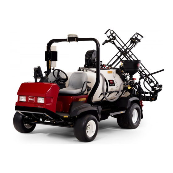
Toro Multi Pro 5800-G Operator's Manual
Turf sprayer with excelarate spray system
Hide thumbs
Also See for Multi Pro 5800-G:
- Operator's manual (96 pages) ,
- Software manual (36 pages) ,
- Operator's manual (104 pages)

Related Manuals for Toro Multi Pro 5800-G


Summary of Contents for Toro Multi Pro 5800-G
- Page 1 Form No. 3409-673 Rev E Multi Pro ® 5800-G Turf Sprayer with ExcelaRate Spray System Model No. 41394—Serial No. 400000000 and Up *3409-673* E Register at www.Toro.com. Original Instructions (EN)
- Page 2 The Multi Pro ® turf sprayer is a dedicated turf spray Dealer or Toro Customer Service and have the model application vehicle and is intended to be used and serial numbers of your product ready. Figure 1 by professional, hired operators in commercial illustrates the location of the model and serial numbers applications.
-
Page 3: Table Of Contents
Contents Greasing the Front Steering and Suspension ........... 52 Greasing the Boom Hinges....... 53 Safety ............... 4 Greasing the Actuator-Rod Bearings ....53 General Safety ........... 4 Engine Maintenance ........... 55 Safe Operating Practices........4 Checking the Air Cleaner ........55 Chemical Safety .......... -
Page 4: Safety
Safety accident prevention partially are dependent upon the design and configuration of the machine, these factors are also dependent upon the awareness, concern, Improper use or maintenance by the operator or owner and proper training of the personnel involved in the can result in injury. -
Page 5: Chemical Safety
Chemical Safety • This machine is designed to carry the operator and 1 passenger in the seat provided by the manufacturer. Never carry any additional WARNING passengers on the machine. Chemical substances used in the • Never operate the machine while you are ill, tired, spreader-sprayer system may be hazardous or under the influence of alcohol or drugs. -
Page 6: Operating
• Handle chemicals in a well ventilated area. – Slow down before turning. Do not attempt sharp turns or abrupt maneuvers or other • Have clean water available especially when filling unsafe driving actions that may cause a loss of the spray tank. -
Page 7: Maintenance
Note: For each machine covered in this Operator’s resulting in hand and arm injuries. Manual, a cab installed by Toro is a ROPS. Grip the steering wheel loosely around the • Do not remove the ROPS from the machine. -
Page 8: Safety And Instructional Decals
• If major repairs are ever needed or assistance is • Do not use open pans of fuel or flammable required, contact an Authorized Toro Distributor. cleaning fluids when cleaning parts. • To be sure of optimum performance and safety, •... - Page 9 decal107-8724 107-8724 1. Traction drive 3. To drive in reverse, press the bottom of the pedal rearward and down. 2. To drive forward, press the 4. Vehicle speed increases top of the traction pedal with more pedal pressure. forward and down. decal117-4955 117-4955 1.
- Page 10 decal120-0623 120-0623 1. Tow hitch location 2. Tie down locations decal133-2758 3. Warning—Read the Operator's Manual. 133-2758 1. TEC logic—2 A 8. TEC power—7.5 A 2. TEC power—7.5 A 9. Cruise control—10 A 3. Extra fuse slot—10 A 10. InfoCenter—1 A 4.
- Page 11 decal120-0617 120-0617 decal127-6981 127-6981 1. Pinch point, hand—keep hands away from the hinge. 1. Bypass-return flow 3. Section spray 2. Crushing hazard, boom—keep bystanders a safe distance 2. Flow away from the machine. decal127-6976 127-6976 1. Decrease 2. Increase decal127-6982 127-6982 1.
- Page 12 decal136-2351 136-2351 1. To engage the parking 2. To disengage the parking brake, press down the brake, press and release brake and parking-brake the parking-brake pedal. pedal. decal132-7689 132-7689 1. Auto spray mode 7. Rinse system—off 2. Spray mode 8. Sonic sensor—on 3.
- Page 13 decal120-0619 120-0619 1. Warning—read the Operator's Manual. 5. Tipping hazard—do not turn sharply while traveling fast, drive slowly when turning; use caution and drive slowly when traveling across or up and down slopes. 2. Warning—do not operate this machine unless you are trained. 6. To start the engine, engage the parking brake, insert the ignition key and turn it to the start position.
- Page 14 decal132-7695 132-7695 1. Pump—on 5. Speed control—on 9. Lower the right section. 13. Left section spray 2. Pump—off 6. Speed control—off 10. Raise the right section. 14. Center section spray 3. Agitation—on 7. Lower the left section. 11. Engine speed—fast 15.
-
Page 15: Setup
Important: This sprayer is sold without nozzles. To use the sprayer, you must obtain and install nozzles. Contact your Authorized Toro Distributor for information on the available section kit and accessories. After you install your nozzles and before using the sprayer for the first time, adjust the section bypass valves so that the pressure and application rate remains the same for all sections when you turn 1 or more sections off. -
Page 16: Assembling The Sprayer Tank Fill Fitting
Use the jam nut to compress any spring that measures greater than 3.96 cm (1.56 inches). g191617 Figure 4 1. Quick-disconnect fitting 3. Latches (quick-disconnect g002332 coupling) Figure 3 2. Hairpins 1. Boom-hinge spring 2. Jam nut Rotate the latches open to unlock Repeat the procedure for each spring on both the quick-disconnect fitting from the boom hinges. -
Page 17: Removing The Shipping Bumper
Removing the Shipping Bumper No Parts Required Procedure Remove the bolts, washers, and nuts that secure the shipping bumper to the front chassis plate (Figure g028179 Figure 6 1. Nut 3. Washer 2. Shipping bumper 4. Bolt Remove the shipping bumper from the machine (Figure Note: Discard the bolts, washers, nuts, and... -
Page 18: Product Overview
Product Overview g190621 Figure 7 1. Fresh-water tank 4. Roll bar (ROPS) 7. Drain valve (sprayer tank) 10. Work lights 2. Passenger seat 5. Tank lid 8. Spray pump 3. Operator’s seat 6. Chemical tank 9. Battery g190600 Figure 8 1. -
Page 19: Controls
Controls g216445 Figure 9 1. Work-light switch 6. Storage compartment 2. Steering wheel 7. InfoCenter 3. Pressure gauge 8. Quick Find™ console 4. Fuel gauge 9. Arm rest 5. Passenger-hand hold 10. Ignition switch Vehicle Controls begins to decrease, release the traction pedal slightly to allow the engine speed to increase. - Page 20 Brake Pedal Use the brake pedal to stop or slow the machine (Figure 10). CAUTION If you operate the sprayer with poorly adjusted or worn brakes, you could lose control of the sprayer, resulting in serious injury or death to you or bystanders. Always check the brakes before operating the sprayer and keep them properly adjusted and repaired.
-
Page 21: Sprayer Controls
USB Power Port Sprayer Controls The 2-socket USB power port is located at the back of the armrest. g194424 Figure 12 g195515 1. USB port 2. USB sockets Figure 13 1. Application-rate switch 7. Center-section switch 2. Pressure gauge 8. Left-section switch 3. - Page 22 Spray-Pump Switch The spray-pump switch is located on the center console to the right of the seat (Figure 13). Toggle this switch forward to run the spray pump or rearward to stop the pump. When the switch is turned on, a light on the switch illuminates.
- Page 23 Section Bypass Valves Anti-Siphon Fill Receptacle The section bypass valves are used to adjust the At the front of the tank cover is a hose receptacle sprayer system pressure to the section valves in with a threaded fitting, a 90-degree barbed fitting, order to ensure that the sprayer pressure to the spray and a short hose, which you can direct toward the section remains constant no matter how many spray...
-
Page 24: Specifications
9. Exit Wheel base 198 cm (78 inches) 5. Button 3 Optional Equipment—The Toro Company has optional equipment and accessories that you can purchase separately and install on your sprayer. Contact your Authorized Service Dealer for a complete list of optional equipment that is currently available... -
Page 25: Operation
Checking the Tire Air Pressure Operation Service Interval: Before each use or daily Note: Determine the left and right sides of the Check the tire air pressure in the tires to ensure machine from the normal operating position. proper levels. Fill the tires to 138 kPa (20 psi). Think Safety First Note: Also, check the tires for wear or damage. -
Page 26: Preparing To Use The Sprayer
Filling the Fuel Tank DANGER In certain conditions during fueling, static Fuel tank capacity: approximately 45 L (12 US gallons). electricity can be released, causing a spark the can ignite the fuel vapors. A fire or Park the machine on a level surface, engage explosion from fuel can burn you and others the parking brake, shut off the spray pump, shut and can damage property. - Page 27 Align a drain pan under the pressure filter (Figure 22). g033577 Figure 20 2. Retainer 1. Suction hose Remove the hose and hose fitting from the filter housing (Figure 20). Pull the suction strainer out of the filter housing in the tank (Figure 21).
-
Page 28: Operating The Machine
Cleaning the Nozzle Filter Park the machine on a level surface, engage the parking brake, shut off the sprayer pump, shut off the engine, and remove the key. Remove the nozzle from the spray turret (Figure 23). g028263 Figure 24 1. -
Page 29: Breaking In A New Sprayer
Breaking in a New Sprayer Note: The traction pedal returns to the N EUTRAL position. Service Interval: After the first 100 hours To stop quickly, press the brake pedal. • Check the engine-oil and fluid levels regularly Note: The stopping distance of the machine and be alert for indications of overheating in any may vary depending on the sprayer-tank load component of the sprayer. -
Page 30: Filling The Fresh-Water Tank
Filling the Spray Tank no single material which is perfect for all foreseeable applications. Important: Ensure that the chemicals you use are Some chemicals are more aggressive than others compatible with Viton™ (see the manufacturer's and each chemical interacts differently with various label;... -
Page 31: Operating The Spray Sections
Operating the Boom-Transport Important: Prior to introducing wettable powders into any Toro Spray System mix Cradle the powders in a suitable container with sufficient fresh water to create a free flowing The sprayer is equipped with a boom-transport cradle slurry. Failure to do so may result in that has a unique safety feature. -
Page 32: Sprayer Functions For Application Rate Mode And Manual Mode
Sprayer Functions for Application Rate Mode and Manual Mode Refer to the Software Guide for the Multi Pro 5800-D and 5800-G turf sprayers with ExcelaRate spray system for information on the following: Before Operation • The InfoCenter home screen • The main menu screen •... - Page 33 Note: to the Software Guide for the Multi Pro 5800-D Use the master section switch to start and 5800-G turf sprayers with ExcelaRate spray and stop the flow of chemicals to the selected system. spray sections. Set the spray section switch(es) to the O When finished spraying, set the master section position (Figure...
- Page 34 Preparing for the Catch Test Set the individual section switches, as needed, to the O position; refer to Figure 29 Spraying Ensure that the sprayer tank is clean; refer to in the Application Rate Mode (page 32). Cleaning the Sprayer System (page 36).
- Page 35 Compare the volume of water in the graduated container with the nozzle volume in the 15-second catch test table. 15-Second Catch Test Table Nozzle Color Milliliters Ounces collected collected in 15 in 15 seconds seconds Yellow 12.8 Brown 16.0 g193177 Gray 19.2 Figure 34...
-
Page 36: Taking Proper Turf Care Precautions While Operating In Stationary Modes
Refer to the nozzle-selection guide that is Important: Under some conditions, heat from the available through your Authorized Toro Dealer. engine, radiator, and muffler can damage grass when operating the sprayer in a stationary mode. The turret bodies can accept up to 3 different nozzles. - Page 37 Remove the nozzles and clean them by hand. Toro recommends using the approved Clean Rinse Kit Note: Replace damaged or worn nozzles. for this machine. Contact your Authorized Toro Dealer for more information.
-
Page 38: Setting The Section-Bypass Valves
Setting the Section-Bypass Nozzle Application Rate Table Valves Nozzle Color SI (Metric) English Turf Yellow 17 gpa 0.39 gpk 159 L/ha Manual Mode Only 319 L/ha 34 gpa 0.78 gpk Important: When operating in application rate Brown 394 L/ha 42 gpa 0.96 gpk mode, you must set the section-bypass valves to Gray... -
Page 39: Agitation-Bypass Valve Knob Position
Agitation-Bypass Valve • If the pressure gauge indicates 689 kPa (100 psi), the agitation-bypass valve is properly Knob Position calibrated. • • If the pressure gauge indicates differently, The agitation-bypass valve is in the full open continue to the next step. position as shown in Figure 39A. -
Page 40: Locating The Spray Pump
Locating the Spray Pump Engine Messaging There are 2 categories of engine messages that The spray pump is located near the back of the tank on the left side (Figure 41). display on the InfoCenter when the engine is running outside the safe operating limit: •... - Page 41 g194663 g194665 Figure 43 Figure 45 Active Fault Message (Coolant Temp Too High) Stop Engine Messages Press button 1 through 5 to view the active fault list (Figure 44). When an stop engine message displays in the • Press button 1 or 2 to navigate up or down InfoCenter, the operator should immediately park the the list.
-
Page 42: Hauling The Machine
g002211 Figure 49 1. Rear tie-down point g194663 Figure 47 Towing the Sprayer Press button 1 through 5 to view the active fault list ; refer to Figure 44 Engine Advisories In case of an emergency, the sprayer can be towed Messages (page 40). - Page 43 g002214 Figure 52 1. Rear towing points g187500 Figure 50 Release the parking brake. Tow the sprayer at less than 4.8 kph (3 mph). 1. Tow valve When finished, close the tow valve and torque it to 7 to 11 N∙m (5 to 8 ft-lb). Important: If you do not open the tow valve before towing the sprayer, you will damage...
-
Page 44: Spray Filter Recommendations
Spray Filter When you spray at a higher application rate, consider using an courser optional suction-filter mesh; refer Recommendations Figure Selecting a Suction Filter Standard Equipment: 50 mesh suction filter (blue) Use the suction filter table to identify the screen mesh for the spray nozzles you are using based on chemicals products or solutions with a viscosity equivalent to water. - Page 45 Selecting a Pressure Filter Available screen sizes include: Standard Equipment: 50 mesh suction filter (blue) Use the pressure filter table to identify the screen mesh for the spray nozzles you are using based on chemicals products or solutions with a viscosity equivalent to water.
- Page 46 Selecting a Nozzle-Tip Filter (Optional) Note: The use the optional nozzle-tip filter to protect the spray-nozzle tip and increase its service life. Use the nozzle-tip filter table to identify the screen mesh for the spray nozzles you are using based on chemicals products or solutions with a viscosity equivalent to water.
-
Page 47: Maintenance
Maintenance Note: Download a free copy of the electrical or hydraulic schematic by visiting www.Toro.com and searching for your machine from the Manuals link on the home page. Recommended Maintenance Schedule(s) Maintenance Service Maintenance Procedure Interval • Replace the hydraulic-fluid filters. -
Page 48: Daily Maintenance Checklist
Maintenance Service Maintenance Procedure Interval • Grease the actuator-rod bearings. • Complete all yearly maintenance procedures specified in the engine operator's manual. • Check the fuel lines and connections. • Service the fuel filter. • Drain and clean the fuel tank. •... -
Page 49: Notation For Areas Of Concern
Immediately after every washing, regardless of the interval listed Notation for Areas of Concern Inspection performed by: Item Date Information CAUTION If you leave the key in the starter switch, someone could accidently start the engine and seriously injure you or other bystanders. Remove the key from the starter switch before you do any maintenance. -
Page 50: Accessing The Engine
Installing the Forward-Heat Shield Align the rear flange of the forward heat shield over the forward flange of the rear heat shield (Figure 62). g203111 Figure 60 1. Rear jacking points g028177 Accessing the Engine Figure 62 1. Front of the machine 3. - Page 51 g189584 g189583 Figure 64 1. Engine mount 4. Flange locknuts (5/16 inch) 2. Bolt—shown for clarity; do 5. Front of the machine not remove 3. Mounting tabs (undercarriage shroud) Move the mounting tabs off of the bolts that secure the undercarriage shroud to the engine-mount brackets.
-
Page 52: Lubrication
Every 50 hours/Yearly (whichever comes first) with the holes in the seat base (Figure 65). Grease Type: No. 2 lithium grease. Toro Premium Assemble the seat-base-access panel to the All-Purpose Grease is available from your Toro seat base with the 2 flanged-head bolts (Figure Distributor. -
Page 53: Greasing The Boom Hinges
g187456 Figure 67 1. Grease fitting g002014 Figure 69 Right Boom 1. Grease fitting Wipe off excess grease. Repeat the procedure for each boom pivot. g187457 Greasing the Actuator-Rod Figure 68 There are 2 fittings at each front wheel. Bearings 1. - Page 54 Repeat steps through to the actuator-rod bearing at the other side of the machine. g013780 Figure 70 1. Actuator 4. Hairpin 2. Actuator rod 5. Clevis pin 3. Boom-pivot-pin housing Swivel the rod-end bearing and apply grease into the bearing (Figure 71).
-
Page 55: Engine Maintenance
Engine Maintenance Note: Do not clean the air-filter element if it is dirty; replace the air-filter element if it is dirty. Install the dust cap onto the air-cleaner body and Checking the Air Cleaner secure the cap with the 2 latches (Figure 72). -
Page 56: Servicing The Engine Oil
Note: Avoid knocking the filter element against the air-cleaner body. Toro Premium Engine Oil is available from your distributor in either 15W40 or 10W30 viscosity. Refer Clean the inside of the dust cap, air-cleaner to the Parts Catalog for part numbers. - Page 57 Changing the Engine Oil Filter day. If the engine was operated, allow the oil to drain back down to the sump for at least 10 minutes before Remove the forward heat shield; refer to checking. Removing the Forward Heat Shield (page 50).
-
Page 58: Checking The Pcv Valve
Changing the Engine Oil Note: If needed, remove the oil-filler cap, add the specified oil to bring the oil level to the full Align a drain pan under the drain plug (Figure mark on the dipstick, and install the oil-filler cap. 75). -
Page 59: Fuel System Maintenance
Fuel System Maintenance DANGER Under certain conditions, fuel and fuel vapors are highly flammable and explosive. A fire or explosion from fuel can burn you and others and can cause property damage. • Use a funnel and fill the tank outdoors, in an open area, when the engine is off and is cold. - Page 60 Replacing the Fuel Filter Rotate the nut for the fuel pump/sending unit counterclockwise and remove the nut and seal Remove the pickup tube of the fuel filter from (Figure the fitting of the fuel pump (Figure 80). Carefully lift and rotate the fuel pump/sending Note: Discard the fuel filter.
-
Page 61: Draining The Fuel Tank
Installing the Fuel Pump and Draining the Fuel Tank Sending Unit Service Interval: Every 400 hours/Yearly (whichever comes first) Support the float arm and pickup tube together and slip the float and fuel filter into the opening Drain and clean the fuel tank if the fuel system in the fuel tank (Figure 79). -
Page 62: Electrical System Maintenance
Servicing the Battery Electrical System Maintenance WARNING Replacing the Fuses CALIFORNIA Proposition 65 Warning The fuse block for the electrical system is located Battery posts, terminals, and related beneath the operator's seat (Figure 81). accessories contain lead and lead compounds, chemicals known to the State of California to cause cancer and reproductive harm. - Page 63 Charging the Battery WARNING Important: Incorrect battery cable routing could Always keep the battery fully charged. This is especially important to prevent battery damage the sprayer and cables causing damage when the temperature is below 32°F (0°C). sparks. Sparks can cause the battery gasses to explode, resulting in personal Remove the battery from the chassis;...
-
Page 64: Drive System Maintenance
Drive System Maintenance Inspecting the Wheels/Tires Service Interval: After the first 8 hours—Torque the wheel-lug nuts. Every 100 hours—Torque the wheel-lug nuts. Every 100 hours—Inspect the condition and wear of the tires. Torque the lug nuts at the front wheels to 75 to 102 g002246 N∙m (55 to 75 ft-lb) and the lug nuts at the rear wheels Figure 84... -
Page 65: Adjusting The Front Wheel Toe-In
Adjusting the Front Wheel Rotate the tie rod to move the front of the tire inward or outward. Toe-in Tighten the tie rod jam nuts when the adjustment is correct. Service Interval: Every 200 hours/Yearly (whichever comes first) Ensure that the steering wheel rotates an equal amount in both directions. -
Page 66: Cooling System Maintenance
Cooling System Maintenance Servicing the Cooling System Service Interval: Every 100 hours—Check the cooling-system hoses for wear and damage. Cooling system capacity: 5.5 L (5.8 US qt) Coolant type: a solution of 50% water and 50% permanent ethylene glycol antifreeze Important: Do not add coolant to an overheated engine until the engine has fully cooled. - Page 67 Changing the Cooling-System Note: The engine thermostat should open when the hand-held thermometer indicates the Fluid coolant temperature is between 79° to 88°C (175° to 190°F). Service Interval: Every 400 hours/Yearly (whichever comes first)—Check the coolant (as Once the coolant has warmed up, top off the directed by the manufacturer) and coolant level to the sealing surface of the cap change if necessary.
-
Page 68: Brake Maintenance
Brake Maintenance Belt Maintenance Adjusting the Brakes Servicing the Alternator Belt If the brake pedal travels more than 2.5 cm (1 inch) before you feel resistance, adjust the brakes as Service Interval: After the first 8 hours follows: Every 100 hours Position the sprayer on a level surface, shut off the spray pump, shut off the engine, and remove Check the condition and tension of the... -
Page 69: Hydraulic System Maintenance
(55 US gallons) drums. See the parts catalog or your Authorized Toro Distributor for part numbers. Alternate hydraulic fluids: If the Toro fluid is not available, other fluids may be used provided they meet all the following material properties and industry specifications. -
Page 70: Servicing The Hydraulic Fluid
Replacing the Hydraulic-Fluid Filters Service Interval: After the first 5 hours Every 400 hours/Yearly (whichever comes first) Use the Toro replacement filter (See your Parts Manual for the correct part number.) g014217 Important: Use of any other filter may void the Figure 92 warranty on some components. - Page 71 Changing the Hydraulic Fluid Service Interval: Every 400 hours/Yearly (whichever comes first) Hydraulic-fluid capacity: 56 L (15 US gallons) of the specified hydraulic fluid or equivalent; refer to Checking the Hydraulic Fluid (page 69). Important: Using any other fluid may void the warranty on some components.
-
Page 72: Sprayer System Maintenance
Sprayer System Shut off the engine, check the hydraulic-fluid level, and check for leaks. Maintenance Dispose of the used fluid at a certified recycling center. WARNING Checking the Hydraulic Lines and Chemical substances used in the spray system may be hazardous and toxic to you, Hoses bystanders, animals, plants, soils or other Inspect the hydraulic lines, hoses, and fittings daily for... -
Page 73: Changing The Suction Filter
Changing the Suction Filter fitting and housing with the retainer that you removed in step 2. Service Interval: Every 400 hours Changing the Pressure Note: Determine the appropriate suction filter mesh size that you need for your job; refer to Selecting a Filter Suction Filter (page... -
Page 74: Changing The Nozzle Filter
Adjusting the Booms to Install the bowl onto the filter head and tighten by hand (Figure 99). Level Install the plug into the bowl and tighten by hand (Figure 99). The following procedure can be used to adjust the actuators on the center boom to keep the left and right booms at level. -
Page 75: Inspecting The Nylon Pivot Bushings
Extend the outer-boom sections to the spray position and support the booms using stands or straps and lifting equipment. With the weight of the boom supported, remove the bolt and nut securing the pivot pin to the boom assembly (Figure 103). -
Page 76: Pump Maintenance
Position the sprayer on a level surface, engage replace if necessary. (see an Authorized Toro the parking brake, shut off the spray pump, shut Service Distributor). off the engine, and remove the key. -
Page 77: Cleaning The Agitation And Section Valves
Cleaning the Agitation and Section Valves • To clean the agitation valve; refer to the following sections: Removing the Valve Actuator (page 77) Removing the Agitation-Manifold Valve (page 78) Cleaning the Manifold Valve (page 81) Assembling the Manifold Valve (page 82) Assembling the Manifold Valve (page 82) g012934 Installing the Valve Actuator (page 85) - Page 78 Removing the Agitation-Manifold Valve Remove the quick connect pin that secures the quick-connect coupler for the agitation hose to the manifold for the agitation valve (Figure 106). g032545 Figure 105 Section-Valve Actuator Shown (the agitation valve actuator is similar) 1. Actuator (section valve) 3.
- Page 79 Removing the Section-Manifold Valve Remove the quick-connect pin that secures the quick-connect coupler for the section-bypass valve to the section-manifold valve (Figure 108). g191302 Figure 107 1. Manifold (agitation valve) 4. Flange-head bolt (1/4 x 3/4 inch) 2. Valve support 5.
- Page 80 Move the section-valve manifold and gaskets down to clear the section-bypass valve and then away from the machine (Figure 110). Note: If needed, loosen the mounting hardware for the left or right section-valve manifolds as needed to provide clearance. Note: Retain the flange clamps, gaskets and quick-connect pins for installation in Installing...
- Page 81 Cleaning the Manifold Valve Position the valve stem so that it is in the closed position (Figure 111B). g027562 Figure 111 1. Valve open 2. Valve closed Remove the 2 end-cap-fitting assemblies from g028243 Figure 112 each end of the manifold body (Figure 112 Agitation Valve Manifold Figure...
- Page 82 Assembling the Manifold Valve Check the condition of the outlet fitting O-rings (section-valve manifold only), end cap O-rings, back seating O-rings, and ball seat for damage or wear (Figure 112 Figure 113). Note: Replace any damaged or worn O-rings or seats. Apply grease to the valve stem and insert it into the valve-stem seat (Figure 112...
- Page 83 Installing the Section-Manifold Valve Align the 2 gaskets that you removed in Removing the Section-Manifold Valve (page to the flanges of the section-valve manifold (Figure 115). Note: If needed, loosen the mounting hardware for the left or right section-valve manifolds as needed to provide clearance.
- Page 84 Torque the flange-head bolts and flange locknuts to 1978 to 2542 N∙cm (175 to 225 in-lb). Tighten the 2 flange clamps by hand (Figure 117). Assemble the quick-connect coupler of the section hose onto the quick-connect fitting of the section-valve manifold with the quick-connect (Figure 116).
-
Page 85: Storage
Installing the Valve Actuator Storage Align the actuator to the manifold valve (Figure 105). Position the sprayer on a level surface, engage the parking brake, shut off the spray pump, shut Secure the actuator and valve with the retainer off the engine, and remove the key. that you removed in step Removing the Valve Actuator (page... - Page 86 Clean the agitation valve and the 3 be above 4°C (40°F), check the water section valves; refer to Cleaning the level in the battery and charge it Agitation and Section Valves (page 77). every 30 days. Check the brakes; refer to Adjusting the Note: Do not connect the battery cables...
-
Page 87: Troubleshooting
Troubleshooting Troubleshooting the Engine and Vehicle Problem Possible Cause Corrective Action The starter does not rotate the engine. 1. The electrical connections are 1. Check the electrical connections for corroded or loose. good contact. 2. A fuse is blown or loose. 2. - Page 88 Problem Possible Cause Corrective Action The engine overheats. 1. The crankcase-oil level is incorrect. 1. Fill or drain to the Full mark. 2. The coolant level is low. 2. Check the coolant level and replenish it as needed. 3. The engine is operated under 3.
- Page 89 Problem Possible Cause Corrective Action A spray section valve is leaking. 1. An O-ring is deteriorated. 1. Disassemble the valve and replace the seals using the Valve Repair Kit; contact your Authorized Service Dealer. 2. A valve seat is worn or damaged. 2.
-
Page 90: Schematics
Schematics g034336 Sprayer System Schematic (Rev. DWG 131-9559 Rev A) - Page 91 Notes:...
- Page 92 Countries Other than the United States or Canada Customers who have purchased Toro products exported from the United States or Canada should contact their Toro Distributor (Dealer) to obtain guarantee policies for your country, province, or state. If for any reason you are dissatisfied with your Distributor's service or have difficulty obtaining guarantee information, contact the Toro importer.