Table of Contents
Advertisement
Advertisement
Table of Contents

Related Manuals for AnyCubic Prusa i3


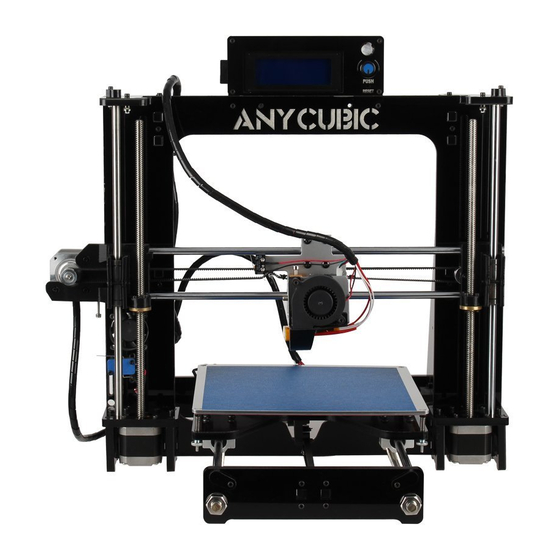
Summary of Contents for AnyCubic Prusa i3
- Page 2 This manual takes the black acrylic sheets for example, if you have chosen the transparent ones, the assembly and setup are the same. The firmware has been pre-uploaded to the ANYCUBIC board, you only have to level the print platform and start printing right after the assembly.
-
Page 3: Table Of Contents
List ■Mechanical assembly ....................1 1. Longmen Frame ....................1 2. Main framework ....................3 2.1 Front and back plate................... 3 2.2 Right side and left side plate ..............5 2.3 Smooth rods ....................7 2.4 Y axis motor ....................9 2.5 Y axis idler wheel.................. -
Page 4: Mechanical Assembly
■Mechanical assembly 1. Longmen Frame Parts list Items Quantity Images Longmen frame PA01 Cooling fan PB48 Z motor mounting plate PA11 Z motor support plate PA10 M3*16 Allan screws PB16 M3 square nuts PB27 M3*25 Allan screws PB19 M3 Hexagon nut PB26... - Page 5 Preview: Front Right Left ① Fixing the cooling fan (PB48) to the BACK of Longmen frame (PA01) with 3 pairs of M3×25 (PB19) screws and M3 (PB26) hexagon nuts. The side with the fan label faces OUTSIDE. ② Use M3×16 Allan screws (PB16) and M3 square nut (PB27) to fix the Z motor support plates (PA10) onto Z motor mounting plate (PA11).
-
Page 6: Main Framework
2. Main framework 2.1 Front and back plate Parts list Items Quantity Images M10 screw rod PB01 M10 washer PB31 M10 spring washer PB32 M10 hexagon nut PB30 Front plate PA02 Back plate PA06... - Page 7 Preview: ① Put two screw rods M10 (PB01) through the round holes at bottom of the Longmen frame. ② Sequentially put M10 washer (PB31), M10 spring washer (PB32), M10 nut (PB30), M10 nut (PB30), M10 spring washer (PB32) and M10 washer (PB31) on the screw rod. ③...
-
Page 8: Right Side And Left Side Plate
Tips: >Do not tighten the nuts until next step. You may need to adjust the position. >Make sure the endstop is located in the back-left. 2.2 Right side and left side plate Parts list Items Quantity Images Right side plate PB07 Left side plate PB06... - Page 9 Preview: Install right and left side plates onto Longmen frame and back plate, with M3x16 Allan screw (PB16) and M3 square nut (PB27). Tips: >It is essential to have a rigid structure for good prints later. Make sure the longmen frame, front, back, right and left side plates are vertical to the table.
-
Page 10: Smooth Rods
2.3 Smooth rods Parts list Items Quantity Images φ8 smooth rods (Y axis) PB02 SCS8UU linear bearing PB34 Stopper PA12 M3*20 Allan screw PB18 M3 hexagon nut PB26 Preview: ① Fix two stoppers (PA12) onto back plate, using two M3x20 (PB18) screws and M3 hexagon nuts (PB26). - Page 11 ② Insert two smooth rods (PB02) respectively from the front plate, then put two linear bearings SCS8UU (PB34) on each of the smooth rods before they reach into the back plate. Then fix two smooth rod stops on front plate to block the smooth rods. ③...
-
Page 12: Y Axis Motor
2.4 Y axis motor Parts list Items Quantity Images Motor PC03 Y motor mounting plate PA14 Y motor support plate PA15 M3*12 Allan screw PB15 M3*20 Allan screw PB18 GT2 synchronizing wheel PB36 Y motor cable PC05 M3 square nut PB27... - Page 13 Preview: ① Fix the synchronizing wheel (PB36) on the motor, and tighten the screws on the wheel, one of the screws MUST face against the plane on motor shaft. ② Fix the motor onto the mounting plate (PA14) using four M3*12 Allan screw (PB15), and plug in motor cable (PC05).
-
Page 14: Y Axis Idler Wheel
2.5 Y axis idler wheel Parts list Items Quantity Images Idler wheel support plate PA16 M3 hexagon nut PB26 PB20 M3×35 Phillips screw PB18 M3×20 Allan screw M3 Square nut PB27 H type idler wheel PB37... - Page 15 Preview: ① Hold the M3×35 screw (PB20), then s equentially put through idler wheel plate (PA16), M3 hex nut (PB 26), idler wheel (PB 37), M3 hex nut again, another idler wheel plate and M3 hex nut. Tight the M3 nut but make sure idler wheel rotating smoothly.
-
Page 16: Y Axis Belt
2.6 Y axis belt Parts list Items Quantity Images Belt PB10 Belt tensioner PC16 Belt tension spring PB11 Cable tie PB08 Preview: ① Pass one end of belt (PB10) through the belt tensioner (PC16), and fix it with cable ties (PB08), then lead the other end go through idler wheel and synchronizing wheel of Y-axis motor, and then fix it with cable ties and cut off the redundant belt. -
Page 17: Print Platform
② If the belt is loose, we can tighten it using the tensioner spring (PB11). Move the belt tensioner just above the bottom of longmen frame, and install the spring as shown in the image. Tips: >You may loose the Y axis motor mounting plate or the idler wheel plates beforehand, and tighten them again after belt is installed. - Page 18 M3 adjustable round nut PB28 M3 hexagon nut PB26 Aluminum sheet PA07 Platform support plate PA08 M4×10 button head screw PB25 Spring (Φ0.8mm) PB22 M3 self-locking nut PB29 Preview: (heat bad cable goes toward the rear) ① Fix Platform support plate (PA08) to 4 linear bearings (PB34) with M4x10 button head screw.
- Page 19 ② Fix Y axis belt tensioner to platform support plate with two pairs of M3x16 Allan screw (PB16) and M3 self-locking nut (PB29), and must screw down them. ③ Put the aluminum sheet (PA07) on the top of heat bed (PA09), turn them around and then fix them with 4 pairs of M3x40 Phillips screws (PB21) and M3 hex nuts (PB26).
-
Page 20: Z Axis Motor
Tips: >When fixing the belt tensioner to the platform plate, you may lie the machine down on the side for easy installation. >Manually move the platform forth and back to check if the belt is wobbly. If it does, you may adjust the synchronizing wheel or belt tensioner until it goes straight. - Page 21 Preview: ① Connect the cable onto the Z motors (left and right), and place the motor in place as the image shows above. Then pass the cable through the hole as the images show below. Those cable will connect to the mainboard later. ②...
-
Page 22: Axis
5. X axis 5.1 X axis motor (left side) *Parts list (Number×Quantity) X axis motor GT2 synchronizing M3×12 Allan M3×16 Allan X motor cable PC03×1PCS wheel screw screw PC04×1PCS PB36×1PCS PB15×3PCS PB16×4PCS Spring Φ0.5mm Copper nut M3 self-locking M3×35 Phillips X motor holder PC09×1PCS PB23×1PCS... -
Page 23: Smooth Rods (Right Side)
and make sure one of them facing the shaft plain. Wiring the cable to the motor. 电机接上线。 ③ Fix X motor onto the motor holder using M3×12 Allan screws (PB15), and install the motor cable and make sure the cable goes downward. ④... -
Page 24: Extruder
① Insert the LM8LUU (PB33) into the corresponding hole of the holder. ② Attach 2 pieces of rubber washer on both sides of the idler wheel, and put them inside the holder as the image shows, then use 1 pair of M3×25 Allan screw (PB19) and M3 hex nut to fix them to the holder. - Page 25 M3×20 Allan screw PB18 SCS8UU PB34 SCS8LUU PB35 Air nozzle PC17 Preview: ① Fix SCS8UU (PB34) and SCS8LUU (PB35) to extruder holder (PC12) with M4×8 Button head screw (PB24). Please notice the hole on PB35 is upward.
- Page 26 ② Loose the screw at the neck of Hotend, and screw out the M3×16 Allan screw next to it. Then place the extruder onto extruder holder, and finally fasten the neck screw and put back the M3 ×16 Allan screw. ③...
-
Page 27: X/Z Smooth Rods
5.4 X/Z smooth rods Parts list Items Quantity Images PB14 M3×8 Allan screw φ8 smooth rod (X axis) PB03 φ8 smooth rod (Z axis) PB04 Top plate PA13 M3×16 Allan screw PB16 M3 Square nut PB27 PB18 M3×20 Allan screw M3 Hexagon nut PB26 Stopper... - Page 28 Preview: ① Put two X axis smooth rods (PB03) through the bearings on extruder holder, (left ends into PC15, and right ends into PC14). Make sure the extruder holder can move along the rods smoothly, if not, you may have to check and adjust the position of the bearings on extruder holder. ②...
-
Page 29: Axis Belt
④ Push the X axis smooth rods from PC14 into the end of PC15, and tighten 4 pre-installed screws on PC14. Tighten Tips: >Manually slide the extruder, if there is any friction, please adjust the relative position of the bearings on extruder holder. >Please notice the direction of every part and refer to the images above. - Page 30 Preview: ① Pass one end of the belt through the synchronizing wheel on PC15. ② Feed the other end of the belt through the idler wheel on PC14. ③ Using cable tie to fix one end of the belt onto X belt tensioner (PB38). Use the hexagon screw to mount the belt tensioner onto SCS8LUU but do not tighten now.
-
Page 31: Power Supply
④ Manually pull tight the other end of the belt, then tighten the hex screw on SCS8LUU (the tensioner will be pushed on belts). Next, use cable tie to fix the other end of belt. Tips: >Cut off the excessive belt after the installation just in case. >Manually slide the extruder to see if the belt is wobbly. - Page 32 Preview: ① Please select the CORRECT power mode (110V or 220V, and 220V is the default). ② Use M3×12 Allan screw (PB15) and M3 hex nut (PB26) to fix the power supply (PC01) onto right-side plate. ③ Use M3×12 Allan screw (PB15) and M3 hex nut (PB26) to fix switch set (PC02) on right side plate, and pass the wires through the small hole nearby, and connect those wires to power supply (shown in wiring instruction later).
- Page 33 ④ Lead the 12V power line through the small hole as well, and connect those wires to the power supply. ★wiring instruction...
-
Page 34: Lcd
a. Connect the wires of switch and to power supply, (N to N, L to L, E to E) b. Connect the 12V power line to power supply, red wires to +V and black wires to COM. You may use the cable tie to fix the 12V power line to the bottom M10 screw rod. Tips: >Must carefully check if those wires have been connected stably and correctly, and do not let the parts of platform touch the wires. - Page 35 Preview: ① Assemble LCD fix plate (both sides), LCD and LCD cover (PA03) together with M3x20 Allan screws and M3 hex nuts. Then connect the LCD cable. Next fix the whole set to the top of Longmen frame with M3x20 (PB18) Allan screws and M3 hex nuts. Tips: >Perhaps you've received an extra pin board with LCD, you will not going to use it here.
-
Page 36: Limit Switches
8. Limit switches Parts list Items Quantity Images X axis limit switch PB44 Y axis limit switch PB45 Z axis limit switch PB46 M2.5×12 Allan screw PB12 M2.5 hexagon nut PB13 PB18 M3×20 Allan screw M3 hexagon nut PB26 ① Fix X-axis limit switch to extruder holder with M2.5x12 Allan screw and M2.5 hex nut. ②... - Page 37 ③ Fix Z-axis limit switch to bottom left side of longmen frame with M2.5x12 Allan screw and M2.5 hex nut. Tips: > Limit switches have to be steadily installed in order to be triggered normally.
-
Page 38: Wiring Of Mainboard
9. Wiring of mainboard ANYCUBIC has developed a new version of motherboard, TRIGORILLA. The wiring of TRIGORILLA is shown as following. You may use the E1 port as one of the Z axis motor. (Please note the DIRECTION of motor driver) - Page 39 I=U/0.8. Adjust U to 0.75~1V, if you have no multimeter, you can still turn the adjustable resistor clockwise to the position approximately as the following figure. Mount 5 A4988 on ANYCUBIC motherboard correctly to avoid any unnecessary damages during operation.
- Page 40 to the length of wires when move to the max position, and make sure the length is enough for the moving parts. ④ Wiring of mainboard ★ Wire 12V power line from the power supply to the corresponding port on the mainboard. red to +, black to -.
- Page 41 ★ motor cable > X motor, insert it to the corresponding port. > Y motor, insert it to the corresponding port. > Z motor, insert two cables to the corresponding ports, Z and E1 (interchangeable)
- Page 42 >Extruder motor cable to E0 port. ★ LCD cable. Please make sure EXP1 connects to EXP1 and EXP2 connects to EXP2. ★ Heat rod wires to HEATER0 port on mainboard. (interchangeable) ★ Heat bed lines to HOTBED port on the mainboard. (red to + and black to -)
- Page 43 ★ Cooling fan wires (on longmen frame) go to FAN1 port on mainboard. (red to + and black to -) ★ P type cooling fan (on extruder) wires go to FAN0 port. (red to + and black to -) ★ Limit switches (no positive and negative). But do not connect the limit switches to the ‘V’ row (at the edge) to avoid any damage to the mainboard.
- Page 44 > Z limit switch goes to Z- ★ Thermistor wiring >The wires of thermistor of extruder goes to T0 (no positive and negative) > The wires of heat bed goes to T1 (no positive and negative) ⑤ Using M3×8 Allan screw to fix the mainboard onto the copper double screw bolt Till now, the assembly has been finished.
-
Page 45: Setup/Print
1. Communication Driver ANYCUBIC TriGorilla mainboard uses CP2102 as communication chip. When you connect Anycubic i3 to PC for the first time, the system should install the CP2102 drive automatically. Open “Device Manager”, choose “CP2102”, right-click it and update the drive. Otherwise you could find the driver for manual installation via the link above. - Page 46 Attention: the serial port should be the same as the Device Manger (on your PC) shows, AUTO will not be accepted. Other parameters: (Cura will show the corresponding information when mouse stays on the icon) Print speed: printing too fast may make printer shaky, 20~60 is suggested. Printing temp: PLA should be 190~210℃, and ABS should be 230~240℃.
-
Page 47: Leveling
2. Leveling The level of first layer is the base of a model, and it matters for the print quality. For ANYCUBIC i3 printer, it’s convenient to level the platform manually, and you don't need to level it every time. -
Page 48: Faq
1. PC cannot identify the motherboard. Please refer to part one in the Setup/Print section. 2. Slicing software cannot comunicate with printer. For CURA, you have to choose the right serial port (not Auto). For other slicers, we have to select the right baud rate too, and we’ve set is as 250000 in the firmware.
Need help?
Do you have a question about the Prusa i3 and is the answer not in the manual?
Questions and answers