Advertisement
- 1 Introduction
- 2 Product Overview
- 3 Packing List
- 4 Technical Specification
- 5 Machine Installation
- 6 Check Before Use
- 7 Power-on guide (when ACE Pro is not connected)
- 8 Power-on guide (when ACE Pro is connected)
- 9 Loading Filament
- 10 Printer Binding
- 11 Software Installation and binding
- 12 First print
- 13 Other Function Descriptions
- 14 Leveling
- 15 Maintenance Recommendation
- 16 Attention
- 17 Documents / Resources
Introduction
Maybe you are familiar with 3D printing technology or have purchased ANYCUBIC printers before, but we still highly recommend that you read this manual carefully. The installation techniques and precautions in this manual can help you avoid any unnecessary damage or frustration. Please visit https://support.anycubic.com/ to contact us if you have any question. You can also gain more information such as software, videos, models from the website.
 APP
APP

Wiki

Support Center

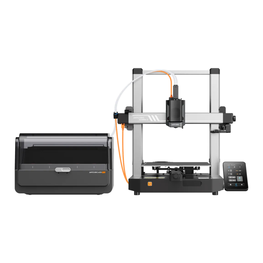
Product Overview


Packing List
The following pictures are for reference only. Please refer to the actual object.

Technical Specification
Printing
Technology: FDM (Fused Deposition Modeling)
Build Size: 250 mm (L) x 250 mm (W) x 260mm (H)
Layer Thickness: 0.08 - 0.28mm positioning Accuracy: X/Y / Z 0.0125 / 0.0125 / 0.0025 mm
Extruder Quantity: Single
Nozzle Diameter: 0.4 mm supported Materials: PLA/TPU/PETG/ABS etc
Temperature
Ambient Operating Temperature: 8 ºC- 40 ºC
Operational Extruder Temperature: Max 300 ºC
Operational print Bed Temperature: Max 110 ºC
Software
Slicing Software: AnycubicSlicer/ PrusaSlicer /Cura /Orca
Software Input Formats: STL/ -OBJ
Software Output Formats: GCode
Connectivity: U-DISK,AC Cloud, AnycubicSlicer
Electrical
Power Input: 110V / 220 V 50 / 60 Hz
Rated Power: 400 W
Physical Dimensions
Printer Dimensions 452.9mm (L) x 504.7mm(W) x 483 mm (H)
Biggest Printer Dimensions: 525.8mm (L) x 521mm (W) x 483 mm (H)
Net Weight: —9.2kg
ACE Pro Dimensions: 365.94mm (L) x 282.8mm (W) x 2343 mm (H)
ACE Pro Net weight: -4.6kg
Machine Installation
For the installation instruction video, please scan the QR code on the right

Connect print head cable

- Press the print head cable (Orange Type-C long cable) down and insert it into the groove above the print head.
- Use the No. 1 bag screw to secure the cable.
Install print head
Install the print head from the back of the printer. Use the No. 2 bag screws to secure the print head by turning it clockwise in the position shown in the figure. It is recommended to fix the two upper screws first and then the lower screws.

Install screen

- Use No. 3 bag screws to install the screen.
- Plug the FPC cable into the port behind the screen by pressing the terminal.
Connect the X-axis motor cable
Insert the motor cable (Orange 6 Pin short cable) upward into the bottom groove on the left side of the X-axis to tighten it. Note that the cable buckle faces forward.

Install cable hoder

- Press down the cable holder to secure it to the groove on the left side of the X-axis.
- Insert the print head cable into the cable holder.
lnstall Purge wiper

- Slide the purge wiper from the back to the front into the groove on the rear side of the X-axis.
- Use the No. 4 bag screw to secure the Purge wiper from the back and bottom of the X-axis.
Install Filament tube
(skip this step if printing in multiple colors)
- Insert one end of the Individually packed short filament tube into the hole above the print head and the other end into the cable holder.
![]()
- Snap the filament tube and print head cable into the cable organizer.
![]()
![caution]() Note: If the filament tube cannot be inserted into the cable holder successfully, you can first remove the blue retainers on the cable holder, insert the filament tube, and then put the blue retainers back to its original position.
Note: If the filament tube cannot be inserted into the cable holder successfully, you can first remove the blue retainers on the cable holder, insert the filament tube, and then put the blue retainers back to its original position.


Install Spool holder
(skip this step if printing in multiple colors)

- Put the cylindrical handle into the spool holder hole, and then rotate it at a certain angle to fix it.
- Press the spool holder down and insert it into the groove behind the printer base.
Install ACE Pro

- Put ACE Pro to the left side of the Kobra 3 printer, spacing 10-15cm.
- Insert the 4-pin end of the cable into the hole on the left side of the peripherals, Note that the cable buckle faces downward
- Insert all four filament tubes into the print head filament hub.
- Pass all four filament tubes through the cable holder.
- Use cable organizer to secure the cable.

- Insert the 6-pin end of the cable into the hole on the left corner of ACE Pro, Note that the cable buckle faces outward.
- Remove the four blue retainers at the filament tube connection port.
- Insert all four filament tubes into the filament tube connection ports of the ACE Pro (Note: filament tubes are matched in no order).
- After completing the above operations, install the four blue retainers back to their original positions.
Check Before Use
- Pulley elastic adjustment
Check if the print head is shaking. If it is, adjust the hexagonal isolation column located underneath the print head until it slides smoothly and without shaking.

Check if the print bed is shaking. If it is, adjust the hexagonal isolation column located underneath slides smoothly and without shaking.

- Belts
Please manually move the print head and print platform. If there is any difficulty or abnormal noise during the movement, adjust the tensioner to ensure smooth sliding of the print head or platform.

- Connecting to Power
Connect the printer and ACE Pro to power outlet with the power cable, then power on the printer.
![]()


 Note:
Note:
- When inserting the power cord, please avoid crossing it with the print head cable to prevent interference.
- Before turning on the power, please check the printer power level matches the local voltage.
Power-on guide (when ACE Pro is not connected)
- Language
![]()
- Area
![]()
- Network
![]()
- Cloud
![]()
- Complete setup
![]()
- Insert U-Disk
![]()
- SeIf Test
![]()
- Auto-Level
![]()
- Load Filament
![]()
- Vibration compensation
![]()
- Print The Model
![]()


Note: The current interface is for reference only. Due to ongoing feature upgrades, please refer to the Ul of the latest firmware release for accurate information.
Power-on guide (when ACE Pro is connected)
- Language
![]()
- Area
![]()
- Network
![]()
- Cloud
![]()
- Complete setup
![]()
- Insert U-Disk
![]()
- Self Test
![]()
- Auto-Level
![]()
- Load Filament
![]()
- Vibration compensation
![]()
- Print The Model
![]()


Note: The current interface is for reference only. Due to ongoing feature upgrades, please refer to the Ul of the latest firmware release for accurate information.
Loading Filament

- Place at least one roll of filament in ACE Pro.
- Insert one end of the filament into the filament inlet, and ACE Pro will automatically pre-load the filament after detecting it.
- Press the [Filament) interface, click to select a filament, and then edit mark will appear. Select the corresponding and color and click save, lf you use Anycubic RFID filament, the filament color and material will be automatically
- After completing the above operations, click (Extrude), wait for the nozzle to heat to the preset temperature, filament will be extruded from the nozzle.
Printer Binding

- Please connect the printer to the network first.
- Scan the QR code on the Printer screen, QR code path: ( Settings) - (Cloud), download the ANYCUBIC App, register and log in to the ANYCUBIC account.
- Open ANYCUBIC App, click [+intiate printing], click [Scan],and scan the QR code on the Printer screen to bind ANYCUBIC account.
Software Installation and binding
- Software installation procedure
Open the attached USB Drive and navigate into the path: \FiIes_EngIish_Anycubic Kobra 3 combo\Anycubic Slicer, choose Windows /IMac to install the corresponding version, double-click on the Anycubic Slicer application to begin the installation - Please connect the printer to the network before performing the following operations.
- Anyubic Slicer usage instruction:
Open the attached USB Drive and navigate into the path:\FiIes_EngIish_Anycubic Kobra 3 combo\Anycubic Slicer \Anycubic Slicer _ Usage Instructions
- After the software installation is completed, enter the main interface and click (Workbench) or (Log in to begin remote print)

- lf you already have an APP account, you can directly enter your account and password to log in. If not, click [Sign Up Now].

- Click (Add Printer)
![]()
- Automatically find printers on the same LAN as the current device. If the APP has been bound to the machine and logged in to the same account, the information will be automatically synchronized

- Select the machine that needs to be bound in the automatic search results and click (Add Now] Multiple printers can be connected; if the search is not successful, please click (Connect with device CN code) Or [connect with APPI

- If the search fails, enter the CN code of the device to connect. Find the CN code path: Select [Settings-Cloud Platform -More Information) on the printer You can view the CN code


Note: The software interface is subject to the latest version
First print
- Select a model from the local or U-DISK and start printing. *We recommend using one Of the pre-loaded files as a first test print.


Note : The built-in model is subject to reality
Other Function Descriptions
Vibration Compensation: To achieve better printing results, it is recommended to perform a vibration compensation check after printing for more than 300 hours or when the machine has been moved. This feature helps reduce the occurrence of banding during high-speed printing. Regular vibration compensation checks help maintain the stability and accuracy of the printer, thereby improving print quality.
Press "Tools" - "Control" - "Vibration compensation" and wait for the machine to complete the calibration. Please do not touch the machine during the calibration process.
Filament Runout Detection: This function is designed to prevent printing failures when the filament runs out during the middle of a print. It alerts the user to replace the filament before continuing the print, effectively preventing wasted prints due to filament shortage.
Power Loss Resume:when printing using the filament holder, in the event of a sudden power outage or accidentally turning off the machine, this function does not require manual setup. Simply reconnect the power and turn on the machine. You can then resume the print.
Note:
ACE pro currently does not have the function of power loss resume
Leveling
Press "Tools" - "Control" - "Auto Level". Wait for the machine to complete the leveling process.

Note: Please check whether the PEI magnetic spring board is installed before leveling.
Maintenance Recommendation
Z-axis Lead Screws
*The Z-axis lead screw needs regular lubrication, as proper lubrication ensures smooth movement.lt is recommended to perform maintenance every three months.
Before applying lubricating grease to the Z-axis lead screws, it is important to clean them thoroughly, removing any dust or plastic particles. Then, using the axis movement controls, move the print head to a higher position. Apply a thin coat Of lubricating grease on the Z-axis lead screws, and then home the printer again.
You can repeat this movement process a few times to ensure the grease is evenly distributed over the Z-axis lead screws. Once completed, clean off any excess lubricating grease that may have accumulated near the lead screw nuts.

X/ Y-axis double metal spindles
*The X/ Y-axis double metal spindles require regular lubrication, as proper lubrication ensures smooth movement.lt is recommended to perform maintenance once a month.
Before applying lubricating grease to the X/ Y-axis double metal spindles, it is important to clean them thoroughly, removing any dust or plastic particles. Then, apply a thin coat Of lubricating grease on the X/ Y-axis double metal spindles and home the printer. You can repeat the movement process a few times to ensure the grease is evenly spread over the X/Y-axis double metal spindles.

*Please scan the QR code for more maintenance information.

Hotend replacement
- Before replacing the hotend, please cool down the nozzle first, click [Tools] - [Preheat] - [Cooling], wait for the nozzle temperature to drop below 40 degrees, and turn off the printer.
![]()
- Press both sides of the print head lightly and pull the print head front cover forward to remove it.
![]()
- Gently pull the bottom black and white lines forward to remove them.
![]()


- Pull the retaining spring forward to loosen the hotend.
![]()
- Insert the new hotend upwards to the very bottom, and note that the white wire is at the front.
![]()
- Press the retaining spring back to fix the hot end.
- Plug the two wires back to their original positions, and note that the black wire is at the bottom.
- After completing the above operations, close the front cover to complete the hot end replacement.


Attention
- Anycubic 3D printer generates high temperature. DO NOT reach inside of the printer during operation. Contact with extruded materials may cause burns.
- Use high temperature resistant gloves when operating the product.
- This equipment is not suitable for use in locations where children are likely to be present.
- The fuse rating for the printer is 250V 10A. Never replace the fuse with one of a higher amperage, otherwise it may cause fire.
- The socket-outlet shall be easily accessible.
If the above problems cannot be solved, please initiate consultation in our after-sales service system, and our engineers will reply you in the form of email within one working day.
(https://support.anycubic.com/)
Warm tips:

- Fill in the information based on the SN of the corresponding model. The items with red dots are mandatory.
- If the order is successful, you will soon receive a reply from the after-sales service system in your mailbox.
- If you successfully place an order but do not receive an email, please watch out for spam.
- If the order creation fails, please pay attention to the pop-up reminder on the web page.
Documents / Resources
References
Download manual
Here you can download full pdf version of manual, it may contain additional safety instructions, warranty information, FCC rules, etc.
Advertisement


Need help?
Do you have a question about the Kobra 3 Combo and is the answer not in the manual?
Questions and answers