Table of Contents
Advertisement
Air-conditioner Control System
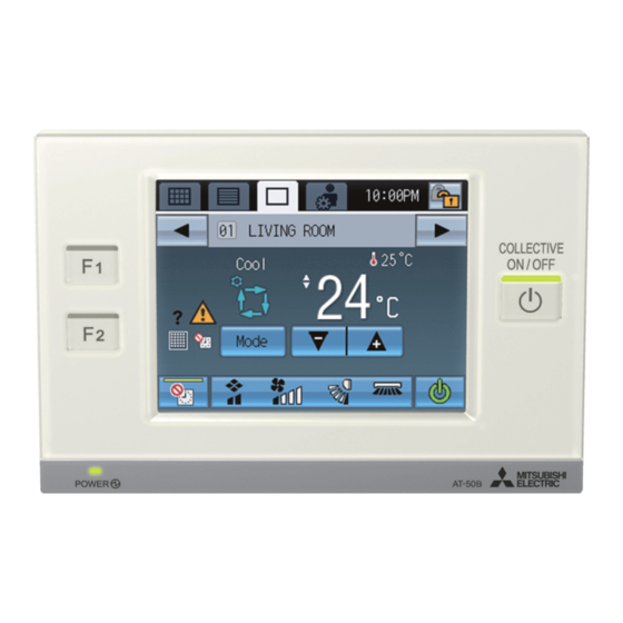
Advanced Touch Controller AT-50B
Installation Manual
Chapter 1. Installation
Thoroughly read the following safety precautions prior to installation. Refer to Chapter 2. "Initial Setting" in this manual, and the Instruction Book for
information on operating or making the settings for the controller. Also, refer to the air conditioning unit installation manuals for how to connect cables or how
to install air conditioning units.
1-1. Safety Precautions
• Thoroughly read the following safety precautions prior to installation.
• Observe the following precautions to ensure safety.
WARNING
Indicates a risk of death or serious injury.
CAUTION
Indicates a risk of serious injury or structural damage.
• Nomenclature
(Prohibited actions)
(Do not touch)
• After reading this manual, pass it on to the end user to retain for future reference.
• Keep this manual for future reference and refer to it as necessary. This manual should be made available to those who repair or relocate the controller.
Make sure that the manual is passed on to any future AT-50B users.
General precautions
WARNING
Do not install the unit in a place where large amounts of oil, steam, organic
solvents, or corrosive gases, such as sulfuric gas, are present or where acidic/
alkaline solutions or sprays are used frequently. These substances can
compromise the performance of the unit or cause certain components of the
unit to corrode, which can result in electric shock, malfunctions, smoke, or fire.
To reduce the risk of shorting, current leakage, electric shock, malfunctions,
smoke, or fire, do not wash the controller with water or any other liquid.
To reduce the risk of electric shock, malfunctions, smoke or fire, do not operate
the switches/buttons or touch other electrical parts with wet hands.
CAUTION
To reduce the risk of fire or explosion, do not place flammable materials or use
flammable sprays around the controller.
To reduce the risk of damage to the controller, do not directly spray insecticide
or other flammable sprays on the controller.
To reduce the risk of electric shock or malfunctions, do not touch the touch
panel, switches, or buttons with a pointy or sharp object.
Precautions during installation
WARNING
Do not install the controller where there is a risk of leaking flammable gas.
If flammable gas accumulates around the controller, it may ignite and cause a
fire or explosion.
Properly dispose of the packing materials. Plastic bags pose suffocation hazard
to children.
CAUTION
To reduce the risk of shorting, current leakage, electric shock, malfunctions,
smoke, or fire, do not install the controller in a place exposed to water or in a
condensing environment.
(No water)
(No wet hands)
All electric work must be performed by qualified personnel.
For distribution to dealers and contractors
(Fire hazards)
(Electric shock hazards)
To reduce the risk of injury or electric shock, before spraying a chemical around
the controller, stop the operation and cover the controller.
To reduce the risk of injury or electric shock, stop the operation and switch off
the power supply before cleaning, maintaining, or inspecting the controller.
Properly install all required covers to keep moisture and dust out of the controller.
Dust accumulation and water can cause electric shock, smoke, or fire.
To reduce the risk of injury, keep children away while installing, inspecting, or
repairing the controller.
To reduce the risk of injury and electric shock, avoid contact with sharp edges
of certain parts.
To avoid injury from broken glass, do not apply excessive force on the glass
parts.
To reduce the risk of injury, wear protective gear when working on the
controller.
Take appropriate safety measures against earthquakes to prevent the
controller from causing injury.
To prevent injury, install the controller on a flat surface strong enough to
support its weight.
Controller must be installed by qualified personnel according to the instructions
detailed in the Installation Manual.
Improper installation may result in electric shock or fire.
– 1 –
WT06990X04
(Injury hazards)
(Important actions)
<ORIGINAL>
(Grounding required)
Advertisement
Table of Contents

Related Manuals for Mitsubishi Electric AT-50B


Summary of Contents for Mitsubishi Electric AT-50B
-
Page 1: Chapter 1. Installation
• Keep this manual for future reference and refer to it as necessary. This manual should be made available to those who repair or relocate the controller. Make sure that the manual is passed on to any future AT-50B users. - Page 2 Do not attempt to play this CD-ROM on an audio CD player as this may damage your ears and/or speakers. The CD-ROM that is supplied with AT-50B has Installation Manual and Instruction Book in English, German, French, Spanish, Italian, Portuguese, Russian, Swedish, simplified Chinese, and traditional Chinese.
-
Page 3: Parts List
Receives power from the power supply unit for transmission cable or 30VDC*1 Power source from outdoor units via the M-NET transmission cable. The power (for connection to M-NET only) consumption coefficient*2 of AT-50B is “4.” Operating temperature range 0˚C~40˚C [32˚F~104˚F] Temperature Operating conditions Storage temperature range -20˚C~+70˚C [-4˚F~+158˚F]... - Page 4 *1 The power consumption coefficient of AT-50B is 4 and that of an indoor unit is “1”*, which means that each AT-50B unit consumes power equivalent to four indoor units. (*Indoor units receive power through the M-NET transmission cable to maintain communication during power failure.) Refer to the CITY MULTI DATABOOK for details.
- Page 5 (1-3/16) 4. Preparation (1) Install a breaker on the power supply unit side before installing the controller. (2) Select an installation site for the AT-50B. AT-50B outline • Install the controller at the user's eye level for easy operation. 50 (2) •...
- Page 6 • To route the cable along the wall surface: A, B It is approximately 10 cm (4 in) from the cable access hole on the back of AT-50B to the M-NET terminal block. Trim off the excess transmission cable, if any.
- Page 7 (1) External signal input Using external dry contact signals, the following operation of all air conditioning units can be controlled from the AT-50B: Emergency stop/Normal operation, ON/OFF, Permit/Prohibit local remote controller operation. These settings are made on the External Input Settings on the Initial Settings screen that is accessible from the Service Menu.
- Page 8 Note • External output of the AT-50B is a dry contact. Select an external power supply suitable for the relays used (12 VDC or 24 VDC). • To prevent malfunction, connect the external power supply to the input circuit with the correct polarity.
-
Page 9: Using An Sd Memory Card
1-8. Using an SD memory card The AT-50B has a slot for an SD memory card at the bottom that can be used to update software. Bottom of controller Refer to section “To Update The Software (as necessary)” on the last page for the detailed information about updates. -
Page 10: Chapter 2. Initial Setting
This chapter contains information about the settings to be made at the time of installation. Please read the instructions carefully and make the settings accordingly. Refer to Chapter 1. “Installation” for how to install the AT-50B Advanced Touch Controller, and refer to the air conditioning unit installation manuals for how to connect the controller cable to the air conditioning units, or how to install the air conditioning units. -
Page 11: Service Menu Screen
2-2. AT-50B Screen Configurations (1) Screen sequence and Service Menu configuration. HOME screen GRID (zoom-out) view GRID (zoom-in) view LIST view GROUP view Touch [ ] or [ Touch [ Main Menu screen Touch [ Touch [ Login Page screen... -
Page 12: Initial Settings
Settings” in the Instruction Book. • AT-50B can be used as a Main controller or a Sub controller. At the time of factory shipment, AT-50B is set as a Main controller. The MAIN/SUB setting can be changed on the Initial Settings 1/Basic System screen from the Service Menu. (Refer to section 2-3(2)-1 for details.) - Page 13 M-NET Address 1) Touch the button labeled 1 in the figure to set the AT-50B controller address on the screen that pops up. • The address can be set to 000 or to a value between 201 and 250 (the factory setting is 201).
-
Page 14: Operation Mode Control
CITY MULTI units. * Set the “Clock setting signal” setting to “OFF” if the AT-50B is used as a sub controller, or other controllers periodically issuing a time alarm exist on the same M-NET. If two or more controllers issuing a time alarm exist on the same M-NET, other devices existing on the M-NET fail to synchronize their clock with that of the main controller (master clock), causing malfunctions of the clock-related functions such as the schedule and apportioned electricity billing functions. -
Page 15: Group Name
AT-50B. In batch and on individual group Units can be turned on or off either collectively or by group from the AT-50B. On individual group Only certain groups of units can be turned on or off from the AT-50B. - Page 16 * Up to 16 indoor units can be assigned to each ventilation unit. 3) After all interlocked operation settings have been made, touch the Save button. (2)-4. Batch deletion (Available only when AT-50B is set as a main controller) To delete all group and interlocked operation settings collectively, follow the procedure below.
- Page 17 (3) During the test run, verify that air conditioned air is blowing out of the supply air outlet. (4) After checking for normal operation of each unit, stop the units through AT-50B or the local remote controllers. * Refer to the unit installation manual for the detailed information about test run.
-
Page 18: Maintenance
* Only the ones whose startup procedures have been successfully completed will appear in the list. Display content The addresses of the outdoor units that are connected to AT-50B will appear. (The number in 1 Outdoor unit address the parentheses indicates the address of the sub unit.) - Page 19 * Consult your dealer if the update is not completed in 10 minutes. 7) After the update has been completed, turn the DIP switch 4 to OFF to restart the AT-50B. When the initialization screen appears, check that the software version that appears at the bottom right corner is correct. If it shows the old version, the update failed.
- Page 20 This product at hand is based on the following EU regulations. - Electromagnetic Compatibility Directive 2014/30/EU - Restriction of Hazardous Substances 2011/65/EU HEAD OFFICE: TOKYO BLDG., 2-7-3, MARUNOUCHI, CHIYODA-KU, TOKYO 100-8310, JAPAN MANUFACTURER: MITSUBISHI ELECTRIC CORPORATION Air-conditioning & Refrigeration Systems Works 5-66, Tebira 6 Chome, Wakayama-city, 640-8686, Japan...