ABB ACS800 Hardware Manual
Acs800-07 (+v992) drives (500 to 2800 kw)
Hide thumbs
Also See for ACS800:
- Firmware manual (340 pages) ,
- Hardware manual (210 pages) ,
- Cabinet installation and operating instruction (162 pages)
Table of Contents
Advertisement
Quick Links
Advertisement
Chapters
Table of Contents

Related Manuals for ABB ACS800


Summary of Contents for ABB ACS800
- Page 1 ACS800 Hardware manual ACS800-07 (+V992) drives (500 to 2800 kW)
-
Page 2: Acs800-07 Manuals
ACS800-07 manuals Hardware manual ACS800-07 (+V992) Drives (500 to 2800 kW) Hardware Manual 3AUA0000068936 Supply unit firmware manual ACS800 Diode Supply Control Program Firmware Manual 3AUA0000068937 Inverter unit firmware manual (Drive application program firmware manual) Standard Control Program Firmware Manual... - Page 3 ACS800-07 (+V992) drives 500 to 2800 kW Hardware manual 3AUA0000068936 REV A EN EFFECTIVE: 2010-03-15 © 2010 ABB Oy. All Rights Reserved.
-
Page 5: Safety Instructions
Safety instructions What this chapter contains This chapter contains safety instructions you must follow when installing, operating and servicing the drive. If ignored, physical injury or death may follow, or damage may occur to the drive, the motor or driven equipment. Read the safety instructions before you work on the unit. -
Page 6: Installation And Maintenance Work
Installation and maintenance work These warnings are intended for all who work on the drive, motor cable or motor. Ignoring the instructions can cause physical injury or death, or damage the equipment. WARNING! • Only qualified electricians are allowed to install and maintain the drive. •... - Page 7 Note: • The main disconnecting device (main breaker or main switch-disconnector) does not switch off the voltage from the auxiliary circuits or the input busbars. • The motor cable terminals on the drive are at a dangerously high voltage when the input power is on, regardless of whether the motor is running or not.
-
Page 8: Grounding
Grounding These instructions are intended for all who are responsible for the grounding of the drive. Incorrect grounding can cause physical injury, death or equipment malfunction and increase electromagnetic interference. WARNING! • Ground the drive, motor and adjoining equipment to ensure personnel safety in all circumstances, and to reduce electromagnetic emission and pick-up. -
Page 9: Operation
Operation These warnings are intended for all who plan the operation of the drive or operate the drive. Ignoring the instructions can cause physical injury or death or damage the equipment. WARNING! • If the drive is equipped with an optional brake unit, make sure there are inverters connected to the intermediate circuit before start. -
Page 10: Permanent Magnet Motor Drives
Application program To control a permanent magnet motor, only use the ACS800 permanent magnet synchronous motor drive application program, or other application programs in the scalar control mode. -
Page 11: Table Of Contents
ACS800-07 (+V992) ........ - Page 12 Other operating switches ........... .34 Control panel .
- Page 13 Protection against short-circuit inside the drive or in the supply cable ....62 Ground fault protection ............63 Emergency stop devices .
- Page 14 Note on cabinet-installed ACS800 drives ........
- Page 15 Altitude derating ........... . . 126 ACS800-07 (+V992) frame sizes and power module types ......127 AC fuses .
- Page 16 Motor connection ............. .132 Efficiency .
- Page 17 Providing feedback on ABB Drives manuals ........
-
Page 18: Table Of Contents
Table of contents... -
Page 19: About This Manual
About this manual What this chapter contains This chapter describes the intended audience and contents of the manual. It contains a flowchart of steps in checking the delivery, installing and commissioning the drive. The flowchart refers to chapters/sections in this manual and other manuals. -
Page 20: Contents
Contents The chapters of this manual are briefly described below. Safety instructions gives safety instructions for the installation, commissioning, operation and maintenance of the drive. About this manual introduces this manual. Hardware description describes the drive. Mechanical installation instructs how to move, place and mount the drive. Planning the electrical installation provides advice on motor and cable selection, the protective functions of the drive, and cable routing. -
Page 21: Installation And Commissioning Flowchart
Check the type designation indicated by the type For instructions on how to disconnect the EMC/ designation label with the original order. If the drive is RFI filtering, contact your local ABB about to be connected to an IT (ungrounded) system, representative. -
Page 22: Terms And Abbreviations
With the ACS800-07 (+V992) (> 500 kW), the frame size of the drive indicates the quantity and frame size of the supply modules, plus the quantity and frame size of the inverter modules, eg, “2×D4 + 4×R8i”. - Page 23 The RMIO board is a versatile control board and an I/O interface. Its use is determined by the control program loaded into the board. The RMIO board is widely used in the ACS800 product series. It is used for controlling drive modules, inverter units, supply units, cooling units, brake units, etc.
- Page 24 About this manual...
-
Page 25: Hardware Description
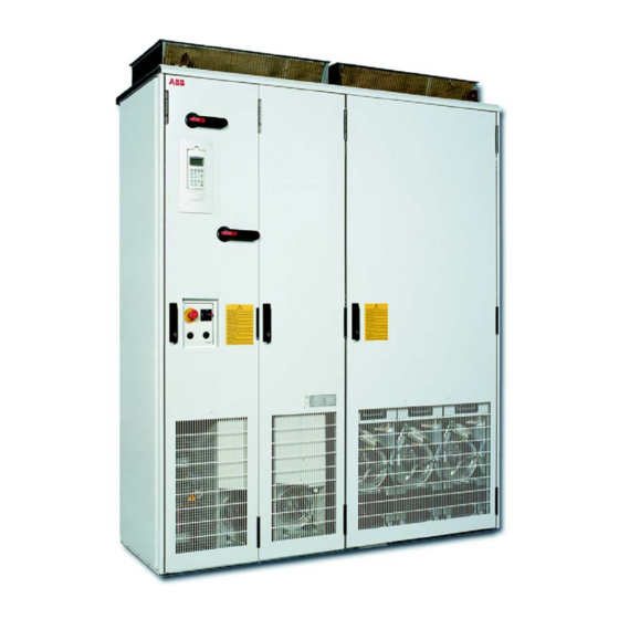
What this chapter contains This chapter describes the construction of the drive in short. ACS800-07 (+V992) ACS800-07 (+V992) is a cabinet-mounted drive for controlling AC motors. Cabinet line-up The drive consists of several cubicles that contain the supply and motor terminals, 1 to 4 diode supply module(s), 2 to 6 inverter modules, and optional equipment. -
Page 26: Single-Line Circuit Diagram Of The Drive, Example 1
Supply unit Inverter unit 400 VAC Input power line Notes: The diagram shows drive type 400 VAC ACS800-07-0610-3+F250 comprising: 230/115 VAC – one DSU module and inverter module (D4 + R8i) Voltage – main switch-disconnectors inside the measurement DSU module (BAMU) –... -
Page 27: Single-Line Circuit Diagram Of The Drive, Example 2
Supply unit Inverter unit 400 VAC 400 VAC Notes: The diagram shows drive type Main ACS800-07-0870-3+F250+F253+F260 supply comprising: – two parallel DSU modules and two parallel 400 VAC inverter modules (2×D4 + 2×R8i) 230/115 VAC – main switch-disconnector (option +F253) –... -
Page 28: Layout Drawing, Example 1
Layout drawing, example 1 The following drawing shows an ACS800-07-0610-3+F250 drive type comprising: • one DSU module and two parallel inverter modules (1×D4 + 2×R8i) • main switch-disconnector inside the DSU module (internal main switch- disconnectors) • main contactors (option +F250) inside the DSU module. -
Page 29: Layout Drawing, Example 2
Layout drawing, example 2 The following drawing shows drive type ACS800-07-0870-3+F253+F259+F260 comprising: • two parallel DSU modules and two parallel inverter modules (2×D4 + 2×R8i) • optional main switch-disconnector (option +F253) and grounding switch (option +F259) • main AC fuses (option +F260) •... - Page 30 Description Input busbars. Main switch-disconnector (option +F253) in a dedicated cubicle. Grounding switch (option +F259). AC fuses. Only present if the drive is equipped with a main switch-disconnector or main breaker. Supply modules. + Behind each module: quick connector. Supply unit control board (mounted sideways). Inverter DC fuses.
-
Page 31: Swing-Out Frame
Swing-out frame The swing-out frame inside the auxiliary control cubicle provides space for the inverter unit control board, control electronics of the drive, I/O terminal blocks, and optional electrical equipment. The lead-throughs for I/O cables, the auxiliary voltage transformer, and further space for additional equipment are available behind the frame. -
Page 32: Power Connections And Control Interfaces Of The Drive
Power connections and control interfaces of the drive The following diagram illustrates the power connections and control interfaces of the drive. The table below gives some additional information on the numbered items. Control Control 0 VDC 0 VDC panel panel +24 VDC +24 VDC Back up c... -
Page 33: Controls Of The Inverter Unit (And Motor)
Direction/Reset/Reference, and the parameter settings for the drive application program. The panel can also be used for the set-up and monitoring of the supply unit. See the Firmware manual of the drive application program and ACS800 diode supply control program firmware manual (3AUA0000068937[English]) for further information. -
Page 34: Controls Of The Supply Unit
Controls of the supply unit The supply unit control program runs in the RDCU control unit located in the swing- out frame. The RDCU is connected to the supply modules by a fibre optic link, and a separate wire set. If there are parallel supply modules, the controls from the RDCU are distributed to the modules with an optical branching unit (APBU board). -
Page 35: Control Panel
For the instructions on the use of the panel, see the appropriate Firmware manual of the drive application program. For details on the supply unit control program, see ACS800 diode supply control program firmware manual (3AUA0000068937[English]). Analog and digital I/O signals The diagram below shows the I/O signal connections of a standard diode supply unit. - Page 36 The default cable connections to the RMIO board of the DSU are shown below. Terminal block size: VREF- Reference voltage -10 VDC, 1 kohm < R < 10 kohm cables 0.3 to 3.3 mm (22 to 12 AWG) Tightening torque: VREF+ Reference voltage 10 VDC, 0.2 to 0.4 Nm (2 to 4 lbf in.)
-
Page 37: Fieldbus
The power loss ride-through function keeps the supply unit operative over an unexpected input power break. You can activate the function and define the delay time in the DSU control program. For more information, see ACS800 diode supply control program firmware manual (3AUA0000068937 [English]). -
Page 38: Type Designation
+ signs (eg, +E202). The main selections are described below. Note: The information below is for quick reference only and does not contain all conditions and details. For more information, refer to ACS800 Ordering Information (code: 64556568), available through ABB representatives. - Page 39 Language of manuals Rxxx Refer to ACS800 Ordering Information (3AFY64556568 [English]). Starter of auxiliary motor M602 = 2.5 … 4 A (1, 2 or 4 pcs) M603 = 4 … 6.3 A (1, 2 or 4 pcs) M604 = 6.3 …...
- Page 40 Selection Alternatives Safety features Q950 = prevention of unexpected start-up (Category 3) Q951 = emergency stop, stop category 0 with opening the main contactor/breaker Q952 = emergency stop, stop category 1 with opening the main contactor/breaker Q954 = ground fault monitoring (IT [ungrounded] system) Q959 = red-coloured trip pushbutton for external breaker Q963 = emergency stop, stop category 0 without opening the main contactor/breaker...
-
Page 41: Mechanical Installation
Mechanical installation What this chapter contains This chapter describes the mechanical installation procedure of the drive. General See chapter Technical data for allowable operating conditions and requirements for free space around the unit. The unit should be installed in an upright vertical position. The floor that the unit is installed on should be of non-flammable material, as smooth as possible, and strong enough to support the weight of the unit. -
Page 42: Moving The Unit
Moving the unit …by crane Use the steel lifting lugs attached to the top of the cabinet. Insert the lifting ropes or slings into the holes of the lifting lugs. The lifting lugs can be removed (not mandatory) once the cabinet is in its final position. If the lifting lugs are removed, the bolts must be refastened to retain the degree of protection of the cabinet. -
Page 43: By Fork-Lift Or Pallet Truck
…by fork-lift or pallet truck The center of gravity may be quite high. Be therefore careful when transporting the unit. Tilting the cabinets must be avoided. The units are to be moved only in the upright position. If using a pallet truck, check its load capacity before attempting to move the unit. -
Page 44: Final Placement Of The Unit
Final placement of the unit The cabinet can be moved into its final position with an iron bar and a wooden piece at the bottom edge of the cabinet. Care is to be taken to properly place the wooden piece so as not to damage the cabinet frame. Mechanical installation... -
Page 45: Before Installation
Before installation Delivery check The drive delivery contains: • drive cabinet line-up • optional modules (if ordered) installed into the control rack at the factory • ramp for extracting supply and inverter modules from the cabinet • hardware manual • appropriate firmware manuals and guides •... -
Page 46: Installation Procedure
Installation procedure See detailed instructions in the following few pages. (1) The cabinet can be installed with its back against a wall, or back-to-back with another unit. Fasten the unit (or first shipping split) to the floor with fastening clamps or through the holes inside the cabinet. -
Page 47: Fastening The Cabinet To The Floor (Non-Marine Units)
Fastening the cabinet to the floor (Non-marine units) The cabinet is to be fastened to the floor by using clamps along the edge of the cabinet bottom, or by bolting the cabinet to the floor through the holes inside. Clamping Insert the clamps into the twin slots along the front and rear edges of the cabinet frame body and fasten them to the floor with a bolt. -
Page 48: Holes Inside The Cabinet
Holes inside the cabinet The cabinet can be fastened to the floor using the fastening holes inside the cabinet, if they are accessible. The recommended maximum distance between the fastening points is 800 mm (31.5”). If there is not enough working space behind the cabinet for mounting, replace the lifting lugs at the top with L-brackets (not included) and fasten the top of the cabinet to the wall. -
Page 49: Fastening The Unit To The Floor And Wall (Marine Units)
Fastening the unit to the floor and wall (Marine units) The unit must be fastened to the floor and roof (wall) as follows: Bolt the unit to the floor through the holes in each flat bar at the base of the cabinet using M10 or M12 screws. -
Page 50: Joining The Shipping Splits
Joining the shipping splits The busbar systems and wiring harnesses of two shipping splits are joined in the common motor terminal cubicle (if present) or a busbar joining cubicle. Special M6 screws for fastening the shipping splits together are enclosed in a plastic bag inside the rightmost cubicle of the first shipping split. -
Page 51: Connecting The Dc Busbars And The Pe Busbar
• Remove any intermediate or partitioning plates covering the rear posts of the joining cubicle. Partitioning plate Intermediate plate Busbar joining Back posts accessible cubicle • Fasten the rear post of the joining section with seven screws (below the busbar joining part) to the rear post of the next cubicle. -
Page 52: Dc Busbars
DC busbars The DC busbar connection is shown below. Joint pieces Tighten the bolts to 55–70 Nm (40–50 ft.-lbs.) Side view of single busbar connection PE busbar The PE busbar runs continuously through the line-up near the floor at the back. The connection is shown below. -
Page 53: Miscellaneous
Miscellaneous Cable duct in the floor below the cabinet A cable duct can be constructed below the 400 mm wide middle part of the cabinet. The cabinet weight lies on the two 100 mm wide transverse sections which the floor must carry. -
Page 54: Cooling Air Intake Through Bottom Of Cabinet
Cooling air intake through bottom of cabinet Units with air intake through the bottom of the cabinet (optional feature) are intended for installation on an air duct in the floor. The required air inlets in the floor are as listed below. Refer also to the dimensional drawings delivered with the unit. •... -
Page 55: Electric Welding
Electric welding It is not recommended to fasten the cabinet by welding. Cabinets without flat bars at the base • Connect the return conductor of the welding equipment to the cabinet frame at the bottom within 0.5 metres of the welding point. Cabinets with flat bars at the base •... - Page 56 Mechanical installation...
-
Page 57: Planning The Electrical Installation
Note: The installation must always be designed and made according to applicable local laws and regulations. ABB does not assume any liability whatsoever for any installation which breaches the local laws and/or other regulations. Furthermore, if the recommendations given by ABB are not followed, the drive may experience problems that the warranty does not cover. -
Page 58: Protecting The Motor Insulation And Bearings
The stress on motor insulation can be avoided by using optional ABB du/dt filters. du/dt filters also reduce bearing currents. - Page 59 Motor type Nominal mains Requirement for voltage (AC line Motor insulation ABB du/dt filter, insulated N-end bearing and ABB common mode voltage) system filter < 100 kW 100 kW < P < 350 kW > 350 kW frame size < IEC 315 frame size >...
- Page 60 For motors with higher rated output than what is stated for the particular frame size in EN 50347 (2001) and for IP 23 motors, the requirements of ABB random-wound motor series M3AA, M3AP, M3BP are given below. For other motor types, see the Requirements table above.
-
Page 61: Permanent Magnet Synchronous Motor
Note 8: Calculating the rise time and the peak line-to-line voltage The peak line-to-line voltage at the motor terminals generated by the drive as well as the voltage rise time depend on the cable length. The requirements for the motor insulation system given in the table are “worst case”... -
Page 62: Thermal Overload And Short-Circuit Protection
Thermal overload and short-circuit protection Thermal overload protection of the drive and the input and motor cables The drive protects itself and the input and motor cables against thermal overload when the cables are dimensioned according to the nominal current of the drive. No additional thermal protection devices are needed. -
Page 63: Ground Fault Protection
Firmware Manual of the drive application program. See the ACS800 Ordering Information (3AFY64556568 [English], available on request) for other available ground fault protection options. The EMC filter (if present) includes capacitors connected between the main circuit and the frame. -
Page 64: Prevention Of Unexpected Start-Up
Prevention of unexpected start-up The drive can be equipped with an optional Prevention of unexpected start-up function according to standards IEC/EN 60204-1: 1997; ISO/DIS 14118: 2000 and EN 1037: 1996. The circuit conforms to EN954-1, Category 3. The function is achieved by disconnecting the control voltage to the power semiconductors of the inverters of the drive. -
Page 65: Safe Torque Off
Note: If you add or modify the wiring in the drive safety circuits, ensure that the appropriate standards (eg, IEC 61800-5-1, EN 62061, EN/ISO 13849-1 and -2) and the ABB guidelines are met. Planning the electrical installation... -
Page 66: Selecting The Power Cables
Selecting the power cables General rules Dimension the supply (input power) and motor cables according to local regulations: • The cable must be able to carry the drive load current. See chapter Technical data for the rated currents. ° • The cable must be rated for at least 70 C maximum permissible temperature of conductor in continuous use. -
Page 67: Alternative Power Cable Types
Alternative power cable types Power cable types that can be used with the drive are represented below. Recommended Symmetrical shielded cable: three phase conductors A separate PE conductor is required if the conductivity and a concentric or otherwise symmetrically of the cable shield is < 50 % of the conductivity of the constructed PE conductor, and a shield phase conductor. -
Page 68: Conduit
Conduit Where conduits must be coupled together, bridge the joint with a ground conductor bonded to the conduit on each side of the joint. Bond the conduits also to the drive enclosure. Use separate conduits for input power, motor, brake resistors, and control wiring. -
Page 69: Power Factor Compensation Capacitors
Power factor compensation capacitors Power factor compensation is not needed with AC drives. However, if a drive is to be connected to a system with compensation capacitors already installed, note the following restrictions. WARNING! Do not connect power factor compensation capacitors to the motor cables (between the drive and the motor). -
Page 70: Before Opening An Output Contactor (In The Dtc Motor Control Mode)
Before opening an output contactor (in the DTC motor control mode) Stop the drive and wait for the motor to stop before opening a contactor between the output of the drive and the motor when the DTC control mode is selected. (See the Firmware Manual of the drive appliction program for the required parameter settings.) Otherwise, the contactor will be damaged. -
Page 71: Selecting The Control Cables
Control panel cable In remote use, the cable connecting the control panel to the drive must not exceed 3 metres (10 ft). The cable type tested and approved by ABB is used in control panel option kits. Coaxial cable (for use with Advant Controllers AC 80/AC 800) •... -
Page 72: Connection Of A Motor Temperature Sensor To The Drive I/O
Connection of a motor temperature sensor to the drive I/O WARNING! IEC 60664 requires double or reinforced insulation between live parts and the surface of accessible parts of electrical equipment which are either non- conductive or conductive but not connected to the protective earth. To fulfil this requirement, the connection of a thermistor (and other similar components) to the digital inputs of the drive can be implemented in three alternate ways:... -
Page 73: Routing The Cables
Routing the cables Route the motor cable away from other cable routes. Motor cables of several drives can be run in parallel installed next to each other. It is recommended that the motor cable, input power cable and control cables be installed on separate trays. Avoid long parallel runs of motor cables with other cables in order to decrease electromagnetic interference caused by the rapid changes in the drive output voltage. - Page 74 Planning the electrical installation...
-
Page 75: Electrical Installation
Electrical installation What this chapter contains This chapter describes the electrical installation procedure of the drive. WARNING! Only qualified electricians are allowed to carry out the work described in this chapter. Follow the Safety instructions on the first pages of this manual. Ignoring the safety instructions can cause injury or death. -
Page 76: Motor And Motor Cable
500 V DC. The insulation resistance of an ABB motor must exceed 100 Mohm (reference value at 25 °C or 77 °F). For the insulation resistance of other motors, please consult the manufacturer’s instructions. -
Page 77: Input Power Connection - Units Without Main Switch-Disconnector Or Main Breaker (No Option +F253 Or +F255)
Input power connection – Units without main switch-disconnector or main breaker (no option +F253 or +F255) Connection diagrams Six-pulse connection, two DSU modules in parallel Notes: • No parallel cabling is shown here. • Each input terminal of the supply modules must be fed through a dedicated fuse. The fuses are specified in Technical data. -
Page 78: Twelve-Pulse Connection, Two Dsu Modules In Parallel
Twelve-pulse connection, two DSU modules in parallel Notes: • No parallel cabling (for each module) is shown here. It is also possible to connect all input power terminals of module 1 to the transformer Y-output and module 2 to the transformer D-output. -
Page 79: Connection Procedure
Connection procedure WARNING! Read and follow the instructions given in Safety instructions. Ignoring the instructions can cause physical injury or death, or damage to the equipment. WARNING! The supply modules are heavy and have a high center of gravity. Be careful when manoeuvring the modules. - Page 80 3. Disconnect the module signal wire set. (C) The counterpart must be used and connected to the wire set instead of the DSU module, when the module is removed from the cabinet. 4. Unplug also the pair of fibre optic cables from its connectors on the front of the DSU module.
-
Page 81: Phase 2 - Installing The Cables
7. Pull the module carefully out of the cabinet along the ramp. (H) Phase 2 – Installing the cables 1. Remove the plastic insulators covering the input power terminals. Electrical installation... -
Page 82: Phase 3 - Replacing The Module
2. Lead the cables into the inside of the cabinet. Make the 360° grounding arrangement at the cable entries as shown below. Grommet (in IP54 units only) 3. Connect the cables as follows: - Twist the cable shields to bundles and connect to the cabinet PE (ground) busbar. -
Page 83: Use Of The Dual-Cable Screw Lug Connector
Use of the dual-cable screw lug connector Removal of the dual-cable screw lug connector Electrical installation... -
Page 84: Input Power Connection - Units With Main Switch-Disconnector
Input power connection – Units with main switch-disconnector or main breaker (option +F253 or +F255) Connection diagrams Six-pulse connection, two DSU modules in parallel Switching, breaking, disconnecting and grounding devices Incoming cubicle Supply module cubicle Notes: Fuses are not required if the input power line is constructed of busbars that withstand the transformer short circuit current, or the input cables will be protected by some other means, eg, by a circuit breaker at the primary side of the transformer. -
Page 85: Twelve-Pulse Connection, Two Dsu Modules In Parallel
Twelve-pulse connection, two DSU modules in parallel Switching, breaking, disconnecting and grounding devices Switching, breaking, disconnecting and grounding devices Incoming cubicle Supply module cubicle Notes: When the same 12-pulse transformer is used to supply more than one module, connect the DC outputs of all modules to a common DC link. -
Page 86: Connection Procedure
Connection procedure WARNING! Read and follow the instructions given in Safety instructions. Ignoring the instructions can cause physical injury or death, or damage to the equipment. Open the door of the incoming (main switch-disconnector or main breaker) cubicle. Remove any shrouds covering the input terminals and cable entries. Lead the cables into the cubicle. -
Page 87: Motor Connection - Units Without Common Motor Terminal Cubicle (No Option +H359)
Motor connection – Units without common motor terminal cubicle (no option +H359) The motor cables are to be connected to the output busbars behind each inverter module. The location and dimensions of the busbars are visible in the dimensional drawings delivered with the drive, as well as the example drawings presented in chapter Dimensions. - Page 88 WARNING! The cabling from all inverter modules to the motor must be physically identical considering cable type, cross-sectional area, and length. Inverter module cubicle Electrical installation...
-
Page 89: Connection Procedure
Connection procedure WARNING! Read and follow the instructions given in Safety instructions. Ignoring the instructions can cause physical injury or death, or damage to the equipment. WARNING! The supply modules are heavy and have a high center of gravity. Be careful when manoeuvring the modules. - Page 90 Lead the cables into the cabinet below each inverter module. Make the 360° grounding arrangement at the cable entry as shown. Grommet (in IP54 units only) Cut the cables to suitable length. Strip the cables and conductors. Twist the cable screens into bundles and connect to cabinet PE (ground) busbar. Connect any separate ground conductors/cables to cabinet PE (ground) busbar.
-
Page 91: Motor Connection - Units With Common Motor Terminal Cubicle (Option +H359)
Motor connection – Units with common motor terminal cubicle (option +H359) Connection diagram Inverter module cubicle Common motor terminal cubicle The recommended cable types are given in chapter Planning the electrical installation Connection procedure See the connection procedure on page Electrical installation... -
Page 92: Control Connections
Control connections Drive/inverter control connections The control connections are made on the terminal blocks provided in the swing-out frame in the auxiliary control cubicle of the drive. Refer to the circuit diagrams delivered with the drive, and to the chapter Motor control and I/O board (RMIO). -
Page 93: Connection Procedure
Connection procedure Turn the main switch-disconnector into open position (or rack the withdrawable main breaker out). Release the door handle and open the door of the auxiliary control cubicle. Remove the two locking screws at the edge of the swing-out frame and open the frame. Run the cables into the inside of the cabinet through the grommets provided. - Page 94 Run the cables to the swing-out frame as shown below. Wherever possible, use the existing cable trunking (1) in the cabinet. Use sleeving wherever the cables are laid against sharp edges. Leave some slack in the cable at the hinge (2) to allow the frame to open fully. Tie the cables to the braces (3) to provide strain relief.
-
Page 95: Installation Of Optional Modules And Pc
Installation of optional modules and PC The optional module (such as fieldbus adapter, I/O extension module and the pulse encoder interface) is inserted into the optional module slot of the inverter unit control board (RDCU) and fixed with two screws. See the appropriate optional module manual for further instructions. -
Page 96: Connections And Tap Settings Of The Auxiliary Voltage Transformer Of The Drive
Connections and tap settings of the auxiliary voltage transformer of the drive 3~ Input Output 3~ input 1~ output 3~ output Tap settings 230 V 400 V (50 Hz) 320 V (60 Hz) Supply Supply Terminals voltage voltage A1 to... B1 to… C1 to… Terminals Terminals Terminals... -
Page 97: Switching On And Selecting The Supply Voltage Of The Auxiliary Voltage Transformer Of The Dsu Module
Switching on and selecting the supply voltage of the auxiliary voltage transformer of the DSU module 1. Detach the lid which covers the switches and selector of the auxiliary voltage transformer of the DSU module. The lid is on the front cover of the module. In the figure below, the lid has been detached already. - Page 98 Electrical installation...
-
Page 99: Motor Control And I/O Board (Rmio)
This chapter shows • external control connections to the control board of the inverter unit with the ACS800 standard control program (Factory macro) • specifications of the inputs and outputs of the board. Note: This chapter describes the standard I/O connections of the RMIO board controlling the inverter unit. -
Page 100: External Control Connections (Non-Us)
External control connections (non-US) External control cable connections to the RMIO board for the ACS800 drive control program (Factory macro) are shown below. For external control connections of other application macros and programs, see the appropriate Firmware manual of the drive application program. -
Page 101: External Control Connections (Us)
External control connections (US) External control cable connections to the RMIO board for the ACS800 drive control program (Factory macro US version) are shown below. For external control connections of other application macros and programs, see the appropriate Firmware manual of the drive application program. -
Page 102: Rmio Board Specifications
RMIO board specifications Analogue inputs With the drive control program two programmable differential current inputs (0 mA / 4 mA ... 20 mA, R = 100 ohm) and one programmable differential voltage input (- 10 V / 0 V / 2 V ... +10 V, R >... -
Page 103: Relay Outputs
Maximum continuous current 2 A rms Isolation test voltage 4 kVAC, 1 minute DDCS fibre optic link With optional communication adapter module RDCO. Protocol: DDCS (ABB Distributed Drives Communication System) 24 VDC power input Voltage 24 VDC ± 10% Typical current consumption... - Page 104 Isolation and grounding diagram (Test voltage: 500 V AC) VREF- AGND VREF+ AGND AI1+ Common mode AI1- voltage between AI2+ channels ±15 V AI2- AI3+ AI3- AO1+ AO1- AO2+ AO2- Jumper J1 settings: DGND1 All digital inputs share a common ground.
-
Page 105: Installation Checklist And Start-Up
Installation checklist and start-up Installation checklist Check the mechanical and electrical installation of the drive before start-up. Go through the checklist below together with another person. Read the Safety instructions on the first pages of this manual before you work on the unit. MECHANICAL INSTALLATION The ambient operating conditions are allowed. -
Page 106: Start-Up Procedure
Start-up procedure This section instructs how to start-up the ACS800-07 drive. The instructions do not cover all possible tasks of all possible variants of the drive as the compositon of the make-to-order drives vary. Always refer to the delivery-specific circuit diagrams when performing the drive start-up. -
Page 107: Connecting Voltage To Input Terminals And Auxiliary Circuit
Action Additional information Connecting voltage to input terminals and auxiliary circuit WARNING! When voltage is connected to the input terminals, voltage may also be connected to the auxiliary circuits of the drive unit(s). Make sure that it is safe to apply voltage. Ensure that: •... -
Page 108: Setting Up The Supply Unit Control Program
[S11] on the cabinet door from 0 to the START position for 2 s. Setting up the supply unit control program Check the settings of the supply unit control program. See section Start-up in ACS800 diode supply control program firmware manual (3AUA0000068937[English]). -
Page 109: What This Chapter Contains
Contact your local ABB Service representative. DSU module Every 12 years Changing the capacitor See Capacitors. Consult your local ABB Service representative for more details on the maintenance. On the Internet, go to http://www.abb.com/drives and select Drive Services – Maintenance and Field Services. -
Page 110: Redundancy (Reduced Run Capability)
Redundancy (Reduced run capability) If one of the parallel-connected supply or inverter modules must be taken out of the cabinet for service, it is possible to continue operation using the remaining modules at reduced power. Removing a DSU module and selecting the Reduced run feature Note: The maximum number of removed DSU modules is limited to 50% of the original number of parallel-connected modules. - Page 111 Firmware manual of the drive application program. 9. Set the number of the existing supply modules and activate the Reduced run function with parameter 16.10 INT CONFIG USER. For more information, refer to ACS800 diode supply control program firmware manual (3AUA0000068937[English]). Maintenance...
-
Page 112: Removing An Inverter Module And Selecting The Reduced Run Feature
8. Make the necessary parameter adjustments in the drive firmware. Refer to the appropriate Firmware manual of the drive application program. For example, if the ACS800 standard control program is in use, decrease the number of parallel inverter modules to the appropriate value by parameter 95.03 INT CONFIG. -
Page 113: Replacing The Ppcs Branching Unit (Apbu-Xx) Memory Backup Battery
Replacing the PPCS branching unit (APBU-xx) memory backup battery WARNING! Read and follow the instructions in chapter Safety instructions. Ignoring the instructions can cause physical injury or death, or damage to the equipment. 1. Switch off the power to the unit and open the main disconnecting device. Close the grounding switch (option +F259) if there is one. -
Page 114: Checking And Replacing The Air Filters
Checking and replacing the air filters WARNING! Read and follow the instructions in chapter Safety instructions. Ignoring the instructions can cause physical injury or death, or damage to the equipment. 1. Switch off the power to the unit and open the main disconnecting device. Close the grounding switch (option +F259) if there is one. -
Page 115: Cooling Fans
The actual lifespan of the fan depends on the running time of the fan, ambient temperature and dust concentration. Each supply and inverter module has its own cooling fan. Replacements are available from ABB. Do not use other than ABB specified spare parts. -
Page 116: Replacing The Fan Of The Inverter And Brake Module
Replacing the fan of the inverter and brake module WARNING! Read and follow the instructions in chapter Safety instructions. Ignoring the instructions can cause physical injury or death, or damage to the equipment. 1. Switch off the power to the unit and open the main disconnecting device. Close the grounding switch (option +F259) if there is one. -
Page 117: Replacing The Fans In The Auxiliary Control Cubicle
Replacing the fans in the auxiliary control cubicle WARNING! Read and follow the instructions in chapter Safety instructions. Ignoring the instructions can cause physical injury or death, or damage to the equipment. 1. Switch off the power to the unit and open the main disconnecting device. Close the grounding switch (option +F259) if there is one. -
Page 118: Replacing The Fan In The Incoming Cubicle With The Main Breaker (Option +F255)
Replacing the fan in the incoming cubicle with the main breaker (option +F255) Certain IP2x/IP4x (+B053 and +B054) units with a main breaker are also fitted with two fans at the air outlet on the roof. Replace the fans as follows: WARNING! Read and follow the instructions in chapter Safety instructions. -
Page 119: Replacing The Additional Fans In The Ip54 / Ul Type 12 Drives (+B055 And +B059)
Replacing the additional fans in the IP54 / UL type 12 drives (+B055 and +B059) WARNING! Read and follow the instructions in chapter Safety instructions. Ignoring the instructions can cause physical injury or death, or damage to the equipment. 1. Switch off the power to the unit and open the main disconnecting device. Close the grounding switch (option +F259) if there is one. - Page 120 Maintenance...
-
Page 121: Heatsinks
It is not possible to predict a capacitor failure. A capacitor failure is usually followed by damage to the unit and an input cable fuse failure, or a fault trip. Contact ABB if a capacitor failure is suspected. Reforming the electrolytic capacitors Reform (re-age) spare part capacitors once a year according to Capacitor reforming guide (code: 64059629 [English], available through your local ABB representative. -
Page 122: Safety Function Checks In The Maintenance Routine
If you replace a circuit board or wire set inside the drive module, re-test the safety function. If you detect any failure in safety functions, contact your local ABB representative. Other maintenance actions Replacement of a supply inverter or brake modules... -
Page 123: Fault Tracing
Fault tracing What this chapter contains This chapter instructs in interpreting the LED indications of the ACS800-07 (+V992) drive. Note: Information on warnings and faults reported by the application program (and displayed on the control panel on the cabinet door) are contained within the Firmware manuals delivered with the drive. -
Page 124: Other Leds Of The Drive
Other LEDs of the drive Location Indication RMIO board (RDCU control unit) Drive in the fault state. Green Power supply on the board is OK. Control panel mounting platform Drive in the fault state. (with the control panel removed) Green Main + 24 V power supply for the control panel and the RMIO board is OK. -
Page 125: Technical Data
CE and other markings. Ratings The ratings for the ACS800-07 (+V992) with 50 Hz and 60 Hz supplies are given below. The symbols are described below the table. Nominal No-over-... -
Page 126: Symbols
At altitudes from 1000 to 4000 m (3281 to 13123 ft) above sea level, the derating is 1% for every 100 m (328 ft). For a more accurate derating, use the DriveSize PC tool. If the installation site is higher than 2000 m (6600 ft) above sea level, please contact your local ABB distributor or office for further information. -
Page 127: Acs800-07 (+V992) Frame Sizes And Power Module Types
ACS800-07 (+V992) frame sizes and power module types Frame size Supply module(s) used Inverter modules used ACS800-07 (+V992) (supply+inverter type Type Type modules) Three-phase supply voltage 380 V, 400 V or 415 V ACS800-07-0610-3 1×D4 + 2×R8i ACS800-704-0910-7 ACS800-104-0390-3 ACS800-07-0770-3 2×D4 + 2×R8i... -
Page 128: Ac Fuses
AC fuses Input ACS800- Rated Type Voltage current 07+V992… Qty. current Clearing at Clearing at (IEC/UL/CSA) Pre-arc type (A RMS) 660V 210000 [A2s] = 400 V (Range 380-415 V) -0610-3 -0770-3 -0870-3 1128 170M6410 -1030-3 1305 31000 210000 210000 Bussmann... -
Page 129: Dc Fuses At Inverter Module Input
DC fuses at inverter module input Input Rated ACS800- Type current Qty. Type (IEC) current Voltage (V) 07… type (UL/CSA) (A RMS) = 400 V (Range 380-415 V) -0610-3 170M8547 170M6216 1250 -0770-3 Bussmann Bussmann -0870-3 1128 -1030-3 1305 170M8550... -
Page 130: Input Power Connection
Input power connection Voltage (U 380/400/415 VAC 3-phase ± 10% for 400 VAC units 380/400/415/440/460/480/500 VAC 3-phase ± 10% for 500 VAC units 525/550/575/600/660/690 VAC 3-phase ± 10% for 690 VAC units Short-circuit withstand Drives without grounding switch (option +F259): Maximum allowable prospective short- strength (IEC 60439-1) circuit current is 65 kA. - Page 131 Input terminals at each Conductor size Max. no. and size of cable Lug hole Bolt Tightening supply module (units without lugs per phase torque main switch-disconnector or IEC Cabling main breaker; no option +F253 or +F255) < 150 mm 2 × 150 mm 1 ×...
-
Page 132: Motor Connection
Motor connection Voltage (U 0 to U , 3-phase symmetrical, U at the field weakening point Frequency DTC mode: 0 to 3.2 × f . Maximum frequency 300 Hz. Nmains · f Nmotor Nmotor where f = frequency at field weakening point; U = mains (input power) voltage;... -
Page 133: Efficiency
Output terminals at each R8i Bottom exit Top exit inverter module (units Side view Side view without common motor Bolt size: M12 or ½” Bolt size: M12 or ½” terminal cubicle, no option Tightening torque: 70 Nm (52 lbf.ft) Tightening torque: 70 Nm (52 lbf.ft) +H359) Cabling direction... -
Page 134: Cooling
Cooling Method Internal fans, flow direction from bottom to top Filter material Inlet (door) Outlet (roof) IP22/IP42 units (+B053 and Luftfilter airTex G150 – +B054) IP54 units (+B055 and Luftfilter airComp 300-50 Luftfilter airTex G150 +B059) Free space around the unit See chapter Mechanical installation. -
Page 135: Materials
EU. They must be removed and handled according to local regulations. For further information on environmental aspects and more detailed recycling instructions, please contact your local ABB distributor. Tightening torques for power connections Screw size Torque M5 3.5 Nm (2.6 lbf.ft) -
Page 136: Applicable Standards
Applicable standards The drive complies with the following standards. The compliance with the European Low Voltage Directive is verified according to standards EN 50178, EN 61800-5-1 and EN 60204-1. • EN 50178 (1997) Electronic equipment for use in power installations. •... -
Page 137: Ce Marking
CE marking A CE mark is attached to the drive to verify that the unit follows the provisions of the European Low Voltage and EMC Directives (Directive 2006/95/EC and Directive 2004/108/EC). Definitions EMC stands for Electromagnetic Compatibility. It is the ability of electrical/electronic equipment to operate without problems within an electromagnetic environment. -
Page 138: Second Environment (Pds Of Category C3)
4. The drive is installed according to the instructions given in the drive manuals. Machinery Directive The drive complies with the European Union Machinery Directive 2006/42/EC requirements for a partly completed machinery. For more information, see the Declaration of Incorporation by ABB Drives at the end of this manual. Technical data... -
Page 139: C-Tick" Marking
“C-tick” marking A “C-tick” mark is attached to each drive in order to verify compliance with the relevant standard (IEC 61800-3 (1996) – Adjustable speed electrical power drive systems – Part 3: EMC product standard including specific test methods), mandated by the Trans-Tasman Electromagnetic Compatibility Scheme. -
Page 140: Second Environment
Second environment The drive complies with the limits of IEC 61800-3 with the following provisions: 1. It is ensured that no excessive emission is propagated to neighbouring low-voltage networks. In some cases, the natural suppression in transformers and cables is sufficient. If in doubt, the supply transformer with static screening between the primary and secondary windings is strongly recommended. - Page 141 Technical data...
- Page 142 Technical data...
-
Page 143: Dimensions
(5.1”) with top entry/exit models as well as units with cooling air intake through the bottom of the cabinet. • The measurements given apply to 6-pulse-input, non-UL/CSA units. For dimensions of 12-pulse-input or UL/CSA units, contact your local ABB representative. The tables are followed by example dimensional drawings. -
Page 144: 1×D4 + 2×R8I
1×D4 + 2×R8i 1300 1300 2000 2000 1490 1700 1700 1190 1600 1600 1060 2300 2300 1660 2000 2000 1360 2100 2100 1250 2800 2800 1850 2500 2500 1550 2400 2400 1420 3100 3100 2020 2800 2800 1720 1500 + 2400 3900 980 + 800 2200 + 2400... -
Page 145: 2×D4 + 2×R8I
2×D4 + 2×R8i 1600 1600 1200 2100 2100 1580 2200 2200 1900 1900 1900 1370 2400 2400 1750 2500 2500 2070 2400 2400 1560 2900 2900 1940 3000 3000 2260 2700 2700 1730 3200 3200 2110 3300 3300 2430 1800 + 2400 4200 1290 + 800 2300 + 2400 4700 1670 + 800... -
Page 146: 2×D4 + 4×R8I
2×D4 + 3×R8i Common Auxiliary Incoming Incoming Supply Inverter motor Shipping Line-up Net weight control cubicle cubicle module module terminal split widths width (kg approx.) cubicle (with +F253) (with +F255) cubicle cubicle cubicle 1800 1800 1350 2300 2300 1730 2400 2400 2050 2200... -
Page 147: 3×D4 + 6×R8I
3×D4 + 5×R8i Common Auxiliary Incoming Incoming Supply Inverter Inverter motor Shipping Line-up Net weight control cubicle cubicle module module module terminal split widths width (kg approx.) cubicle (with +F253) (with +F255) cubicle cubicle 1 cubicle 2 cubicle 2600 2600 2020 3200 3200... -
Page 148: Frame Size 1×D4 + 2×R8I
Frame size 1×D4 + 2×R8i Dimensions... - Page 149 Frame size 1×D4 + 2×R8i (continued) Dimensions...
- Page 150 Frame size 1×D4 + 2×R8i (continued) Dimensions...
-
Page 151: Frame Size 1×D4 + 2×R8I (With A Main Switch-Disconnector +F253)
Frame size 1×D4 + 2×R8i (with a main switch-disconnector +F253) Dimensions... - Page 152 Frame size 1×D4 + 2×R8i (with +F253) (continued) Dimensions...
- Page 153 Frame size 1×D4 + 2×R8i (with +F253) (continued) Dimensions...
- Page 154 Frame size 1×D4 + 2×R8i (with +F253) (continued) Dimensions...
- Page 155 Frame size 1×D4 + 2×R8i (with +F253) (continued) Dimensions...
- Page 156 Frame size 1×D4 + 2×R8i (with +F253) (continued) Dimensions...
-
Page 157: Frame Size 1×D4 + 2×R8I (With Top Entry/Exit)
Frame size 1×D4 + 2×R8i (with top entry/exit) Dimensions... - Page 158 Frame size 1×D4 + 2×R8i (with top entry/exit) (continued) Dimensions...
- Page 159 Frame size 1×D4 + 2×R8i (with top entry/exit) (continued) Dimensions...
-
Page 160: Frame Size 2×D4 + 2×R8I
Frame size 2×D4 + 2×R8i Dimensions... - Page 161 Frame size 2×D4 + 2×R8i (continued) Dimensions...
- Page 162 Frame size 2×D4 + 2×R8i (continued) Dimensions...
-
Page 163: Frame Size 2×D4 + 2×R8I (With A Main Switch-Disconnector +F253)
Frame size 2×D4 + 2×R8i (with a main switch-disconnector +F253) Dimensions... - Page 164 Frame size 2×D4 + 2×R8i (with +F253) (continued) Dimensions...
- Page 165 Frame size 2×D4 + 2×R8i (with +F253) (continued) Dimensions...
-
Page 166: Frame Size 2×D4 + 3×R8I
Frame size 2×D4 + 3×R8i Dimensions... - Page 167 Frame size 2×D4 + 3×R8i (continued) Dimensions...
- Page 168 Frame size 2×D4 + 3×R8i (continued) Dimensions...
-
Page 169: Frame Size 2×D4 + 3×R8I (With A Main Switch-Disconnector +F253)
Frame size 2×D4 + 3×R8i (with a main switch-disconnector +F253) Dimensions... - Page 170 Frame size 2×D4 + 3×R8i (with +F253) Dimensions...
- Page 171 Frame size 2×D4 + 3×R8i (with +F253) Dimensions...
- Page 172 Frame size 2×D4 + 3×R8i (with +F253) Dimensions...
-
Page 173: Frame Size 2×D4 + 3×R8I (With A Main Breaker +F255)
Frame size 2×D4 + 3×R8i (with a main breaker +F255) Dimensions... - Page 174 Frame size 2×D4 + 3×R8i (with +F255) (continued) Dimensions...
- Page 175 Frame size 2×D4 + 3×R8i (with +F255) (continued) Dimensions...
- Page 176 Frame size 2×D4 + 3×R8i (with +F255) (continued) Dimensions...
-
Page 177: Frame Size 3×D4 + 4×R8I (With A Main Switch-Disconnector +F253)
Frame size 3×D4 + 4×R8i (with a main switch-disconnector +F253) Dimensions... - Page 178 Frame size 3×D4 + 4×R8i (with +F253) (continued) Dimensions...
- Page 179 Frame size 3×D4 + 4×R8i (with +F253) (continued) Dimensions...
- Page 180 Frame size 3×D4 + 4×R8i (with +F253) (continued) Dimensions...
-
Page 181: Frame Size 3×D4 + 4×R8I (With A Main Breaker +F255)
Frame size 3×D4 + 4×R8i (with a main breaker +F255) Dimensions... - Page 182 Frame size 3×D4 + 4×R8i (with +F255) (continued) Dimensions...
- Page 183 Frame size 3×D4 + 4×R8i (with +F255) (continued) Dimensions...
- Page 184 Frame size 3×D4 + 4×R8i (with +F255) (continued) Dimensions...
-
Page 185: Common Motor Terminal Cubicle
Common motor terminal cubicle Depending on the drive size, the common motor terminal cubicle is either 300, 400 or 600 mm wide. Refer to the cabinet line-up tables at the beginning of this chapter. Dimensions... - Page 186 300 mm Dimensions...
- Page 187 400 mm Dimensions...
- Page 188 600 mm Dimensions...
-
Page 189: Resistor Braking
Resistor braking What this chapter contains This chapter describes the resistor braking options of the ACS800-07 (+V992). Resistor braking options The following ACS800-07 (>500 kW) drives are available with brake choppers and resistors. ACS800-07 (+V992) Brake chopper type (+D150) Brake resistor type (+D151) -
Page 190: Chopper/Resistor Combinations - Technical Data
= Maximum peak current = Braking power for the specified duty cycle = Corresponding RMS current Brake resistors – Technical data The following table contains the technical data for the resistors supplied by ABB. Rcont Type (ohm) (kJ) (kW) -
Page 191: Verifying The Capacity Of The Braking Equipment
Verifying the capacity of the braking equipment 1. Calculate the maximum power (P ) generated by the motor during braking. 2. Ensure the following condition is met: > P brmax The P values specified in the technical data table above are for the reference braking cycle brmax (1 minute of braking, 9 minutes of rest). -
Page 192: Calculating The Maximum Braking Power (P Br )
Calculating the maximum braking power (P • Braking energy transferred during any ten minute period must be less than or equal to the energy transferred during the reference braking cycle. • The braking power must not exceed the rated maximum value P brmax n x P <... -
Page 193: Example 3
Example 3 Duration of a braking cycle is three minutes. The braking time is 10 seconds. x 60 s brmax < = 1.5 · brmax 4 x 10 s brmax 600 s T = Duration of the braking cycle > P Not allowed. -
Page 194: Custom Resistor Installation And Wiring
+ 70 mm For protection against overheating, resistors with thermal circuit breakers (standard in ABB resistors) should be used. The circuit breakers should be wired to the ENABLE inputs of the brake choppers. WARNING! The ENABLE input terminal blocks of the choppers are at intermediate circuit potential when the supply unit of the ACS800-07 (+V992) drive is running. -
Page 195: Brake Circuit Commissioning
The following is a wiring diagram example of the resistor connection. Brake chopper R‚ R‚ t° Brake resistor Brake circuit commissioning In the drive application program, overvoltage control of the drive must be disabled for correct operation of the brake chopper. Check the drive parameter setting at the start Resistor braking... - Page 196 Resistor braking...
-
Page 199: Further Information
Product and service inquiries Address any inquiries about the product to your local ABB representative, quoting the type designation and serial number of the unit in question. A listing of ABB sales, support and service contacts can be found by navigating to www.abb.com/drives... - Page 200 ABB Oy ABB Inc. ABB Beijing Drive Systems Co. Ltd. Drives Automation Technologies No. 1, Block D, A-10 Jiuxianqiao Beilu P.O. Box 184 Drives & Motors Chaoyang District FI-00381 HELSINKI 16250 West Glendale Drive Beijing, P.R. China, 100015 FINLAND New Berlin, WI 53151...