ABB ACS800 Hardware Manual
Hide thumbs
Also See for ACS800:
- Firmware manual (340 pages) ,
- Hardware manual (210 pages) ,
- Cabinet installation and operating instruction (162 pages)
Table of Contents
Advertisement
Quick Links
Advertisement
Table of Contents

Related Manuals for ABB ACS800


Summary of Contents for ABB ACS800
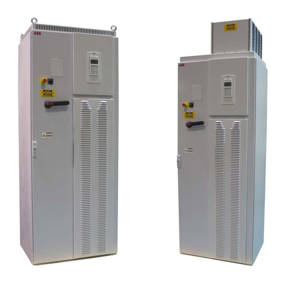
- Page 1 ACS800 Hardware Manual ACS800-PC Drives (150 to 600 HP)
- Page 2 ACS800 Single Drive Manuals HARDWARE MANUALS (appropriate manual is included in the delivery) ACS800-04/U4 Hardware Manual 90 to 500 kW (125 to 600 HP) 3AFE64671006 (English) • Safety instructions • Electrical installation planning • Mechanical and electrical installation • Motor control and I/O board (RMIO) •...
- Page 3 ACS800-PC Drives 150 to 600 HP Hardware Manual 3AUA0000010601 Rev. C EFFECTIVE: 10/16/2009 2009 ABB Inc. All Rights Reserved.
-
Page 5: Safety Instructions
Safety Instructions What this Chapter Contains This chapter contains the safety instructions which you must follow when installing, operating and servicing the drive. If ignored, physical injury or death may follow, or damage may occur to the drive, the motor or driven equipment. Read the safety instructions before you work on the unit. -
Page 6: Installation And Maintenance Work
Installation and Maintenance Work These warnings are intended for all who work on the drive, motor cable or motor. Ignoring the instructions can cause physical injury or death. WARNING! • Only qualified electricians are allowed to install and maintain the drive. •... - Page 7 WARNING! • Cover the drive when installing to ensure that dust from drilling or foreign objects do not enter the drive. Electrically conductive dust inside the unit may cause damage or lead to malfunction. • Ensure sufficient cooling. • Welding of the cabinet frame is not recommended. However, if electric welding is the only way to mount the cabinet, follow the instructions given in chapter "Mechanical Installation".
- Page 8 Grounding These instructions are intended for all who are responsible for the grounding of the drive. Incorrect grounding can cause physical injury, death or equipment malfunction and increase electromagnetic interference. WARNING! • Ground the drive, the motor and adjoining equipment to ensure personnel safety in all circumstances, and to reduce electromagnetic emission and pick- •...
-
Page 9: Operation
Operation These warnings are intended for all who plan the operation of the drive or operate the drive. Ignoring the instructions can cause physical injury or death or damage the equipment. WARNING! • Before adjusting the drive and putting it into service, make sure that the motor and all driven equipment are suitable for operation throughout the speed range provided by the drive. -
Page 10: Permanent Magnet Motor
Permanent Magnet Motor These are additional warnings concerning permanent magnet motor drives. WARNING! Do not work on the drive when the permanent magnet motor is rotating. Also, when the supply power is switched off and the inverter is stopped, a rotating permanent magnet motor feeds power to the intermediate circuit of the drive and the supply connections become live. -
Page 11: Table Of Contents
The ACS800-PC ........ - Page 12 Emergency Stop Devices ......... 35 Prevention of Unexpected Start (ACS800-07/U7 only) ....36 Selecting the Power Cables .
- Page 13 ACS800-PC, ACS800-U7/07) ........97...
-
Page 14: About This Manual
National Electrical Code and local codes are marked with (US). Common Chapters for Products Chapters "Planning the Electrical Installation", "Motor Control and I/O Board (RMIO)" and "Resistor Braking" apply to the ACS800-01/U1, ACS800-02/U2, ACS800-04/U4, ACS800-07/U7, and ASC800-PC. Categorization According to the Frame Size Some instructions, technical data and dimensional drawings which concern only certain frame sizes are marked with the symbol of the frame size R2, R3... -
Page 15: Contents
"Safety Instructions" give safety instructions for the installation, commissioning, operation and maintenance of the drive. "About this Manual" introduces this manual. "The ACS800-PC" describes the drive. "Mechanical Installation" shows how to move and unpack the delivery and how to fasten the cabinet to the floor. -
Page 16: Installation And Commissioning Flowchart
If the converter has been non-operational for more than one year, the converter DC link Only intact units may be started up. capacitors need to be reformed. Ask ABB for instructions. Check the installation site. “Mechanical Installation: Before Installation”... -
Page 17: Inquiries
Inquiries Address any inquiries about the product to the local ABB representative, quoting the type code and the serial number of the unit. If the local ABB representative cannot be contacted, address inquiries to the manufacturing facility. About this Manual... -
Page 18: The Acs800-Pc
The ACS800-PC What this Chapter Contains This chapter describes the construction and operating principle of the drive in short. The ACS800-PC The ACS800-PC is a cabinet-installed drive for controlling AC motors. Drive Control Unit Fuses are located I/O Expansion ... -
Page 19: Type Code
Type Code The type code contains information on the specifications and configuration of the drive. The first digits from left express the basic configuration (e.g. ACS800-PC- 0170-5). The optional selections are given thereafter, separated by + signs (e.g. +E202). The main selections are described below. Not all selections are available for all types. -
Page 20: Product Ordering - Special Note
Product Ordering — Special Note The ACS800-PC-0170-5 through -0440-5 are available with UL Type 1 and UL Type 12. The ACS800-PC-0490-5 through -0610-5 are available with UL Type 12. These units are always supplied with exhaust fan and are not available without the exhaust fan. - Page 21 AC voltage to DC voltage capacitor bank energy storage which stabilizes the intermediate circuit DC voltage six-pulse IGBT inverter converts the DC voltage to AC voltage. The motor operation is controlled by switching the IGBTs. The ACS800-PC...
- Page 22 Motor Control The motor control is based on the Direct Torque Control (DTC) method. Two phase currents and DC link voltage are measured and used for the control. The third phase current is measured for earth fault protection. The ACS800-PC...
-
Page 23: Mechanical Installation
Moving the Unit Move the transport package by truck and pallet truck to the installation site. WARNING! The ACS800-PC is to be handled and shipped standing up ONLY. This unit is not designed to be laid on its back. WARNING! Lift the drive by the upper part only using the lifting lugs/bars attached to the top of the unit. -
Page 24: Before Installation
Schematic: 3AUA0000011083 ACS800-PC-0400-5+B055+K454+L503+L504+L505+M603 Type designation label Requirements for the Installation Site Check the installation site according to the requirements below. Refer to ACS800-PC Dimensional Drawings for frame details. See "Technical Data" for the allowed operation conditions of the drive. Mechanical Installation... - Page 25 Cooling Air Flow Provide the drive with the amount of clean cooling air given in "Technical Data" / "NEMA Ratings". Enclosure Ratings NEMA 1 (NEMA Standard 7-15-1991) Type 1 enclosures are intended for indoor use primarily to provided a degree of protection against limited amounts of falling dirt.
-
Page 26: Fastening The Cabinet To The Floor And Wall
Fastening the Cabinet to the Floor and Wall Fasten the cabinet to the floor with the fastening holes inside the cabinet. When fastening at the back is not possible, fasten the cabinet at the top using L-brackets bolted to the holes of the lifting lugs (M12 bolt). The cabinet can be fastened against a wall or back to back with another cabinet. - Page 27 Fastening the Cabinet Through the Holes Inside the Cabinet The cabinet can be fastened to the floor using the fastening holes inside the cabinet. The maximum allowed distance between the fastening points is 800 mm (31.50 in.). Fastening bolt: M12 (1/2" to 9/16") Bottom View Mechanical Installation...
-
Page 28: Electric Welding
Electric Welding It is not recommended to fasten the cabinet by welding. Cabinets without flat bars at the base If the preferred fastening methods (clamping or bolting through the holes inside the cabinet) cannot be used, proceed as follows: • Connect the return conductor of the welding equipment to the cabinet frame at the bottom within 0.5 metres of the welding point. -
Page 29: Planning The Electrical Installation
Always follow local regulations. Note: If the recommendations given by ABB are not followed, the drive may experience problems that the warranty does not cover. To Which Products this Chapter Applies This chapter applies to the ACS800-01/U1, ACS800-02/U2, ACS800-04/U4, ACS800-PC, and ACS800-07/U7 types up to -0610-X. - Page 30 The stress on motor insulation can be avoided by using optional ABB du/dt filters. du/dt filters also reduce bearing currents.
- Page 31 Requirements Table The following table shows how to select the motor insulation system and when an optional ABB du/dt filter, insulated N-end (non-driven end) motor bearings and ABB common mode filters are required. The motor manufacturer should be consulted regarding the construction of the motor insulation and additional requirements for explosion-safe (EX) motors.
- Page 32 For motors with higher rated output than what is stated for the particular frame size in EN 50347 (2001) and for IP 23 motors, the requirements of ABB random-wound motor series M3AA, M3AP, M3BP are given below. For other motor types, see the "Requirements Table"...
-
Page 33: Permanent Magnet Synchronous Motor
AC power source and the drive. The disconnecting device must be of a type that can be locked to the open position for installation and maintenance work. ACS800-U2 with enclosure extension, ACS800-07, ACS800-U7, and ACS800-PC These units are equipped with a hand-operated input disconnecting device (disconnecting means) which isolates the drive and the motor from the AC power as standard. -
Page 34: Thermal Overload And Short-Circuit Protection
Technical Data). Drive AC Fuses (Standard on ACS800-PC) ACS800-PC units are equipped with Fast Acting Current Limiting Class T (JJS-xxx) fuses listed in Technical Data. The fuses restrict drive damage and prevent damage to adjoining equipment in case of a short-circuit inside the drive. -
Page 35: Emergency Stop Devices
An emergency stop function is optionally available for stopping and switching off the whole drive. Two stop categories according to IEC/EN 60204-1 (1997) are available: immediate removal of power (Category 0 for ACS800-02/U2, ACS800-07/U7, and ACS800-PC) and controlled emergency stop (Category 1 for ACS800-07/U7). -
Page 36: Prevention Of Unexpected Start (Acs800-07/U7 Only)
Prevention of Unexpected Start (ACS800-07/U7 only) The drive can be equipped with an optional Prevention of Unexpected Start function according to standards IEC/EN 60204-1: 1997; ISO/DIS 14118: 2000 and EN 1037: 1996. The Prevention of Unexpected Start function disables the control voltage of the power semiconductors, thus preventing the inverter from generating the AC voltage required to rotate the motor. -
Page 37: Selecting The Power Cables
Selecting the Power Cables General Rules Dimension the mains (input power) and motor cables according to local regulations: • The cable must be able to carry the drive load current. See chapter Technical data for the rated currents. ° • The cable must be rated for at least 70 C maximum permissible temperature of conductor in continuous use. - Page 38 Alternative Power Cable Types Power cable types that can be used with the drive are represented below. Recommended Symmetrical shielded cable: three phase conductors A separate PE conductor is required if the conductivity and a concentric or otherwise symmetrically of the cable shield is < 50 % of the conductivity of the constructed PE conductor, and a shield phase conductor.
-
Page 39: Power Factor Compensation Capacitors
Additional US Requirements Type MC continuous corrugated aluminum armor cable with symmetrical grounds or shielded power cable must be used for the motor cables if metallic conduit is not used. For the North American market, 600 VAC cable is accepted for up to 500 VAC. 1000 VAC cable is required above 500 VAC (below 600 VAC). -
Page 40: Equipment Connected To The Motor Cable
Stop the drive and wait for the motor to stop before opening a contactor between the output of the drive and the motor when the DTC control mode is selected. See the appropriate ACS800 application program firmware manual for the required parameter settings. Otherwise, the contactor will be damaged. In scalar control, the contactor can be opened with the drive running. -
Page 41: Protecting The Relay Output Contacts And Attenuating Disturbances In Case Of Inductive Loads
Protecting the Relay Output Contacts and Attenuating Disturbances in Case of Inductive Loads Inductive loads (relays, contactors, motors) cause voltage transients when switched off. The relay contacts on the RMIO board are protected with varistors (250 V) against overvoltage peaks. In spite of this, it is highly recommended to equip inductive loads with noise attenuating circuits [varistors, RC filters (AC) or diodes (DC)] in order to minimize the EMC emission at switch-off. -
Page 42: Selecting The Control Cables
Control Panel Cable In remote use, the cable connecting the control panel to the drive must not exceed 3 metres (10 ft). The cable type tested and approved by ABB is used in control panel option kits. Planning the Electrical Installation... -
Page 43: Connection Of A Motor Temperature Sensor To The Drive I/O
3. An external thermistor relay is used. The insulation of the relay must be rated for the same voltage level as the main circuit of the drive. For connection, see ACS800 Firmware Manual. Routing the Cables Route the motor cable away from other cable routes. Motor cables of several drives can be run in parallel installed next to each other. - Page 44 A diagram of the cable routing is shown below. Motor cable Drive min 300 mm (12 in.) Power cable Input power cable Motor cable 90 ° min 200 mm (8 in.) min 500 mm (20 in.) Control cables Control Cable Ducts 120 V 120 V 230 V...
-
Page 45: Electrical Installation
For detailed instructions on how to do this, please contact your local ABB representative. WARNING! If a drive with EMC filter +E200 or +E202 is installed on an IT system [an... -
Page 46: Checking The Insulation Of The Assembly
Checking the Insulation of the Assembly Every drive module has been tested for insulation between the main circuit and the chassis (2500 V rms 50 Hz for 1 second) at the factory. Therefore, do not make any voltage tolerance or insulation resistance tests (e.g. hi-pot or megger) on any part of the drive. -
Page 47: Example Wiring Diagram
Example Wiring Diagram The diagram below presents an example for the main wiring. Note that the diagram includes optional components (marked *) which are not always included in the delivery. Electrical Installation... -
Page 48: Power Cable Connection Diagram
Power Cable Connection Diagram Drive OUTPUT INPUT V2 W2 (PE) (PE) External brake resistor (optional) Motor 1), 2) Grounding of the motor cable shield at the motor end If shielded cable is used (not required but For minimum radio frequency interference: recommended), use a separate PE cable (1) or a cable ground the cable shield 360 degrees at the lead-through of the with a grounding conductor (2) if the conductivity of the... -
Page 49: Connecting The Power Cables
Connecting the Power Cables 1. Open the swing-out frame on the top left of the cabinet (if installed) 2. Plan cable access and mark conduit plate accordingly for Input Power (at Front), Output Power (at Rear), and Control wires. 3. Remove the conduit plate from the drive cabinet and cut holes as needed for conduit connections. -
Page 50: Connecting The Control Cables
Connecting the Control Cables Routing the Cables Run the cables to the inside of the cabinet through the conduit plate at the top of the cabinet. The Control cables must be in separate conduit from the power cables. Behind support frame and through grommet Strain Relief Use protective sleeve wherever the cables are against sharp edges. - Page 51 Connecting the Cables to the I/O Terminals Connect the conductors to the appropriate detachable terminals of the RMIO board or optional terminal X2 [refer to chapter "Motor Control and I/O Board (RMIO)"]. Tighten the screws to secure the connection. Insulation Single-shielded cable Double-shielded cable Single-shielded cable: Twist the grounding wires of the outer shield and connect...
-
Page 52: Installation Of Optional Modules
Installation of Optional Modules The optional module (such as a fieldbus adapter, an I/O extension module and the pulse encoder interface) is inserted in the optional module slot of the RMIO board in the RDCU unit and fixed with two screws. - Page 53 Pulse Encoder Module Cabling Clamp as close to the terminals as possible. Alternative to a) Note1: If the encoder is of unisolated As short as type, ground the encoder cable at the possible drive end only. If the encoder is galvanically isolated from the motor shaft and the stator frame, ground the encoder cable shield at the drive and...
-
Page 54: Layout Drawing Of Factory Installed Optional Equipment
Layout Drawing of Factory Installed Optional Equipment +L515, AIMA-01 I/O Expansion option Customer connection Terminal blocks for options +L505 Thermistor and Relay +G313 or +L506 Output for Motor PT100 relay Heater +F250+Q951 Line Contactor and Emergency Stop ... -
Page 55: Motor Control And I/O Board (Rmio)
Motor Control and I/O Board (RMIO) What this Chapter Contains This chapter shows • External control connections to the RMIO board for the ACS800 Standard Application Program (Factory Macro) • Specifications of the inputs and outputs of the board. To Which Products this Chapter Applies This chapter applies to ACS800 units which employ the RMIO board. - Page 56 External Control Connections External control cable connections to the RMIO board for the ACS800 Standard Application Program (Factory Macro US version) are shown below. For external control connections of other application macros and programs, see the appropriate Firmware Manual. RMIO...
-
Page 57: Rmio Board Specifications
RMIO board specifications Analog inputs With Standard Application Program two programmable differential current inputs … (0 mA / 4 mA 20 mA, R = 100 ohm) and one programmable differential voltage … input (-10 V / 0 V / 2 V +10 V, R >... - Page 58 Maximum continuous current 2 A rms Isolation test voltage 4 kVAC, 1 minute DDCS fiber optic link With optional communication adapter module RDCO. Protocol: DDCS (ABB Distributed Drives Communication System) 24 VDC power input Voltage 24 VDC ± 10% Typical current consumption...
- Page 59 Isolation and grounding diagram (Test voltage: 500 V AC) VREF- AGND VREF+ AGND AI1+ Common mode AI1- voltage between AI2+ channels ±15 V AI2- AI3+ AI3- AO1+ AO1- AO2+ AO2- Jumper J1 settings: DGND1 All digital inputs share a common ground. This is the default setting.
-
Page 60: Installation Checklist And Start-Up
Installation Checklist and Start-Up Checklist Check the mechanical and electrical installation of the drive before start-up. Go through the checklist below together with another person. Read the "Safety Instructions" on the first pages of this manual before you work on the unit. Check MECHANICAL INSTALLATION The ambient operating conditions are allowed. -
Page 61: Start-Up Procedure
Start-Up Procedure Action Additional information Safety Only qualified electricians are allowed to start-up the drive. The safety See chapter "Safety Instructions". instructions must be followed during the start-up procedure. Checks with no voltage connected Check the tuning of the insulation monitoring device. Optional device. -
Page 62: Maintenance
Ignoring the safety instructions can cause injury or death. Maintenance Intervals If installed in an appropriate environment, the drive requires very little maintenance. This table lists the routine maintenance intervals recommended by ABB. Interval Maintenance For instruction, see section... -
Page 63: Checking And Replacing The Air Filters
Checking and Replacing the Air Filters Check the inlet air filters at a minimal interval of every 3 months and replace as need depending on accumulated dust and the environment. Inlet filters should be changed at a minimum ever year as part of standard preventative maintenance. The inlet (door) filter may be accessed and replaced by the following procedure. - Page 64 3. Install the replacement filter. Be sure the tuck the filter into the grove around the entire filter frame. This is very important for proper installation. Note: When installing the filter media, the white side must face the outside of the cabinet and the colored side must face the ...
- Page 65 5. Install the filter frame back to the cabinet door. Carefully align the mounting hooks to the slots in the cabinet door. The hooks should be pointing down. Press in at the center of the filter frame with your knee and gently press down with your hands at the top of the frame.
-
Page 66: Exhaust Filter For Ul Type 12
Exhaust Filter for UL Type 12 For UL Type 12 there is also a filter in the exhaust box at the top of the cabinet. Exhaust filters should be inspected every 6 months and replace as needed depending on accumulated dust and the environment. Exhaust filters should be changed at a minimum every year as part of standard preventative maintenance. - Page 67 3. Install the replacement filter. Be sure the tuck the filter into the groove around the entire filter frame. This is very important for proper installation. Repeat this process for the other side. Note: When installing the filter media, the white side must face the outside of the ...
-
Page 68: Heatsink
The module heatsink fins pick up dust from the cooling air. The drive runs into overtemperature warnings and faults if the heatsink is not clean. When necessary, contact ABB for cleaning of the heatsink (frame sizes R7 and R8). Fans The lifespan of the cooling fan of the drive module is about 50,000 hours. -
Page 69: Replacing The Cabinet Fan
Replacing the Cabinet Fan 1. Remove the left and right filter frames of the exhaust fan box by lifting them upwards. 2. Disconnect the fan supply connector from the cabinet roof (top right Inside the cabinet). Maintenance... - Page 70 3. Loosen and remove the four fastening screws at the corners of the fan frame. The screw are through bolts with nuts on the inside of the cabinet. (Do not drop the hardware into the drive). 4. Remove the fan and fan frame as one unit. Maintenance...
- Page 71 Remove the old fan. 6. Install the new fan and capacitor with the replacement part for ABB in the reverse order of the above. Ensure the fan is centered on the velocity stack and rotates freely.
-
Page 72: Layout Of The Drive Module
Layout of the Drive Module The layout stickers of the drive module are shown below. The stickers show all possible components. Not all of them are present in each delivery. Components that need to be changed regularly are listed below: Designation Component Cooling fan... - Page 73 Replacing the Drive Module Fan (R7) 1. Remove the front cover. 2. Disconnect the discharging resistor wire(s). 3. Remove the DC capacitor pack by undoing the red fixing screws and pulling the pack out. 4. Disconnect the fan supply wires (detachable connector). 5.
- Page 74 Replacing the Drive Module Fan (R8) 1. Remove the front cover. 2. Disconnect the fan capacitor and power supply wires. 3. Undo the red fastening screws of the plastic side cover of the fan. Shift the cover to the right to free its right-hand edge and lift the cover off. 4.
-
Page 75: Capacitors
It is not possible to predict a capacitor failure. Capacitor failure is usually followed by damage to the unit and an input cable fuse failure, or a fault trip. Contact ABB if capacitor failure is suspected. Replacements are available from ABB. Do not use other than ABB specified spare parts. - Page 76 Replacing the Capacitor Pack 1. Remove the module from the cabinet as described in section "Replacing the Drive Module". 2. Remove the front cover. Remove the profiled side plate. 3. Disconnect the discharging resistor wires. 4. Undo the red fastening screws. 5.
-
Page 77: Replacing The Drive Module
Replacing the Drive Module 1. Disconnect and lock out power according to local codes. 2. Open top right swing frame above module. Ground cable Input cabling RMIO power supply cable Fuse mounting bolts 3. Disconnect and remove input fuses. Ensure no hardware is dropped in the module. 4. - Page 78 8. Remove Fiber Optic cable from internal connection of drive. When removing the fiber optic cables, pull on the connector, not the cable. Carefully route through the grommets and be very careful not to kink or touch the ends of the fiber optic cables. Any contaminants on the fiber optic cables will reduce signal integrity and may result in failure.
- Page 79 12. With the removed module in a secure position, remove the bus bar fuse stubs from the top of the module and install them on the replacement module before installing the new module in the ACS800-PC cabinet. 13. Install the new module in the reverse order of removal. Secure the module to the cabinet before beginning power and control connections.
-
Page 80: Leds
LEDs This table describes LEDs of the drive. Where When the LED is lit RMIO board Drive in fault state Green The power supply on the board is OK. Control panel mounting platform Drive in fault state Green The main + 24 V power supply for the control panel and the RMIO board is OK. -
Page 81: Technical Data
This chapter contains the technical specifications of the drive, e.g. the ratings, sizes and technical requirements, markings, and warranty policy. NEMA Ratings The NEMA ratings for the ACS800-PC with 60 Hz supplies are given below. The symbols are described below the table. Heat... - Page 82 Symbols maximum output current. Available for 10 s at start, otherwise as long as allowed by drive temperature. Normal use (10% overload capability) continuous rms current. 10% overload is typically allowed for one minute every 5 minutes. typical motor power. The power ratings apply to most 4-pole NEMA rated motors Heavy-duty use (50% overload capability) continuous rms current.
- Page 83 Note 2: Larger fuses must not be used. Note 3: Fuses from other manufacturers can be used if they meet the ratings and specifications. Note 4: Circuit breakers must not be used without fuses. ACS800-PC type Input Fuse current Manufacturer...
- Page 84 Circuit Motor Ground (+D150) Frame Breaker Terminals Lugs Brake Size Resistor Terminals BR+ BR- ACS800-PC-0170-5 350 MCM ACS800-PC-0210-5 2 x 250 350 in-lbs 274 in-lbs ACS800-PC-0270-5 2 x 250 500 in-lbs ACS800-PC-0300-5 ACS800-PC-0320-5 2 x 500 5 Bus Bar Holes...
- Page 85 (480V maximum). The drive provides overload protection in accordance with the National Electrical Code (US). See ACS800 Firmware Manual for setting. Default setting is off; the setting must be activated at start-up.
- Page 86 1% for every 100 m (328 ft). For a more accurate derating, use the DriveSize PC tool. If the installation site is higher than 2000 m (6562 ft) above sea level, please contact your local ABB distributor or office for further information. Technical Data...
-
Page 87: Free Space Around The Unit
Free Space Around the Unit Frame size Required free space around the unit for cooling Front Side Above* * measured from the base plate of the cabinet top 12 in. for fan replacement 15 in. UL Type 1 UL Type 12 Top clearance Space requirement for the door opening: Frame sizes R7 and R8: 800 mm (31.5 in.) -
Page 88: Input Power Connection
Input Power Connection Voltage (L 440/460/480/500 VAC 3-phase ± 10% for 500 VAC units Prospective short-circuit The drive is suitable for use in a circuit capable of delivering not more than 100,000 current symmetrical amperes (rms) at 480 V. Frequency 48 to 63 Hz, maximum rate of change 17%/s Imbalance Max. -
Page 89: Cooling
Cooling Method Internal fan, flow direction from front to top Filter material Inlet (door) Outlet (roof) UL Type 12 3AUA0000006723 (qty 1) 3AUA0000006722 (qty 2) Note: When installing the filter media, the white side must face the outside of the cabinet and the colored side must face the inside of the cabinet Free space around the unit See "Free Space Around the Unit". -
Page 90: Materials
Materials Cabinet Hot-dip zinc coated 1.5 mm thick steel sheet (thickness of coating approximately 20 micrometers). Polyester thermosetting powder coating (thickness approximately 80 micrometers) on visible surfaces. Color RAL 7035 light beige semigloss. Busbars Tin-plated copper Package Wood. Plastic covering of the package: PE-LD, bands PP or steel. Disposal The drive contains raw materials that should be recycled to preserve energy and natural resources. -
Page 91: Ce Marking
European Low Voltage and EMC Directives (Directive 73/23/EEC, as amended by 93/68/EEC and Directive 89/336/EEC, as amended by 93/68/EEC). The ACS800-PC drive with circuit breaker package is intended for use in North America and has been qualified to only the appropriate North American standards. -
Page 92: Equipment Warranty And Liability
(12) months after installation or twenty-four (24) months from date of manufacturing, whichever first occurs. The local ABB office or distributor may grant a warranty period different to the above and refer to local terms of liability as defined in the supply contract. -
Page 93: Dimensional Drawings
Dimensional Drawings UL Type 1 Dimensional Drawing -0170-5 through -0440-5 UL Type 1 Frame Height Width Depth Weight 85.9 in 31.7 in 25.9 in 695 lb 85.9 in 31.7 in 25.9 in 945 lb Example dimensional drawings with dimensions in millimeters and [inches]. Dimensional Drawings... -
Page 94: Dimensional Drawings
UL Type 12 Dimensional Drawing -0170-5 through -0610-5 UL Type 12 Note: -0490-5 through -0610-5 are only available in UL Type 12 enclosure Example dimensional drawings with dimensions in millimeters and [inches]. Frame Height Width Depth Weight 93.6 in 31.7 in 25.9 in 740 lb 93.6 in... -
Page 95: Resistor Braking
The chapter also contains the technical data. To Which Products this Chapter Applies This chapter applies to the ACS800-01/U1 (frame sizes R2 to R6), ACS800-02/U2 (frame sizes R7 and R8), ACS800-04/U4 (frame sizes R7 and R8), ACS800-07/U7 (frame sizes R6, R7 and R8), and ACS800-PC. -
Page 96: Optional Brake Chopper And Resistor(S) For The Acs800-U2, Acs800-U4, Acs800-Pc And Acs800-07/U7
Optional Brake Chopper and Resistor(s) for the ACS800-U2, ACS800-U4, ACS800-PC and ACS800-07/U7 The nominal ratings for dimensioning the brake resistors for the ACS800-U2, ACS800U4, ACS800-PC and ACS800-07/U7 are given below at an ambient temperature of 40 °C (104 °F). -
Page 97: Protection Of Frame Sizes R7 And R8 (Acs800-U2, Acs800-U4, Acs800-Pc, Acs800-U7/07)
Note: If an external brake chopper (outside the drive module) is used, a main contactor is always required. A thermal switch (standard in ABB resistors) is required for safety reasons. The cable must be shielded and not longer than the resistor cable. -
Page 98: Brake Circuit Commissioning
OFF2 STOP. For the use of the brake resistor overload protection (parameters 27.02...27.05), consult an ABB representative. WARNING! If the drive is equipped with a brake chopper but the chopper is not enabled by parameter setting, the brake resistor must be disconnected because the protection against resistor overheating is then not in use. - Page 99 Resistor Braking...
- Page 101 ABB Oy ABB Inc. AC Drives Drives and Power Electronics P.O. Box 184 16250 West Glendale Drive FIN-00381 HELSINKI New Berlin, WI 53151 FINLAND Telephone +358 10 22 11 Telephone 262 785-3200 Telefax +358 10 22 22681 800 243-4384 Internet http://www.abb.com...