Toro Greensmaster TriFlex 3400 Operator's Manual
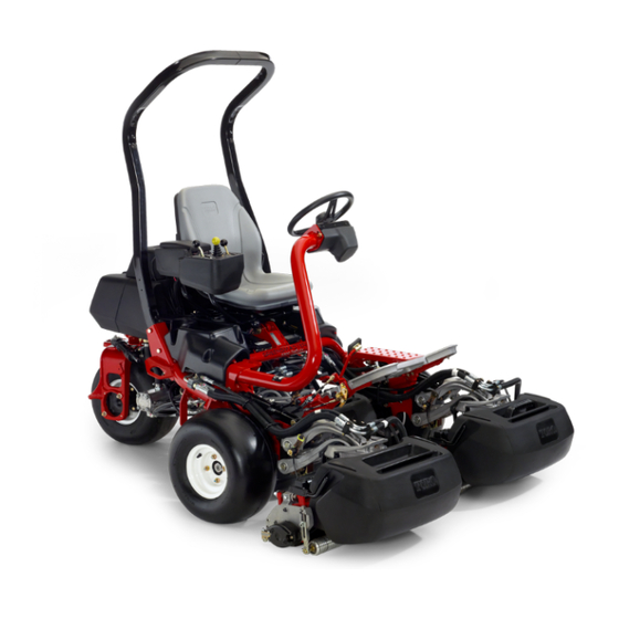
Traction unit
Hide thumbs
Also See for Greensmaster TriFlex 3400:
- Operator's manual (56 pages) ,
- Manual (334 pages) ,
- Service manual (332 pages)

Related Manuals for Toro Greensmaster TriFlex 3400


Summary of Contents for Toro Greensmaster TriFlex 3400
- Page 1 Form No. 3417-544 Rev A Greensmaster ® 3400 TriFlex ® Traction Unit Model No. 04520—Serial No. 400000000 and Up *3417-544* A Register at www.Toro.com. Original Instructions (EN)
- Page 2 Whenever you need service, genuine Toro parts, or additional information, contact an Authorized Service Dealer or Toro Customer Service and have the model and serial numbers of your product ready. Figure 1 identifies the location of the model and serial numbers on the product.
-
Page 3: Table Of Contents
Contents Checking the Torque of the Wheel Nuts .............. 33 Adjusting the Transmission for Neutral....33 Safety ............... 4 Adjusting the Transport Speed......34 General Safety ........... 4 Adjusting the Mowing Speed ......35 Safety and Instructional Decals ......4 Cooling System Maintenance ...... -
Page 4: Safety
Safety • Do not operate the machine without all guards and other safety protective devices in place and working on the machine. This machine has been designed in accordance • Keep clear of any discharge opening. Keep with EN ISO 5395:2013 and ANSI B71.4-2017 and bystanders and pets a safe distance away from meets these standards when the appropriate the machine. - Page 5 decal115-8156 115-8156 1. Reel height 3. 8–Blade cutting unit 5. 14–Blade cutting unit 7. Fast 2. 5–Blade cutting unit 4. 11–Blade cutting unit 6. Reel speed 8. Slow decal115-8155 115-8155 1. Warning—read the Operator's Manual, do not prime or use starting fluid.
- Page 6 decal117-2718 117–2718 decalbatterysymbols Battery Symbols Some or all of these symbols are on your battery. 1. Explosion hazard 6. Keep bystanders a safe distance away from the battery. 2. No fire, open flame, or 7. Wear eye protection; explosive gases can smoking cause blindness and other injuries.
- Page 7 decal132-9548 132-9548 1. Engine speed—fast 7. Reel speed—neutral 2. Engine speed—slow 8. Reel—transport 3. Lower and engage the reels 9. Reel—mow 4. Raise and disengage the reels 10. Reel—backlaping 5. Reel speed—fast 11. Move forward 6. Reel speed—slow decal132-9549 132-9549 1.
- Page 8 decal133-2338 decal133-2339 133-2338 133-2339 Replaces Decal 133-2338 for CE Machines 1. Warning—read the 4. Tipping hazard—slow the Operator’s Manual, do machine before turning, 1. Warning—read the 4. Tipping hazard—do not not operate this machine do not turn at high speeds. Operator’s Manual, do drive across or down unless you are trained.
-
Page 9: Setup
No parts required Install the optional oil cooler. Grass-basket hook Install the grass-basket hooks. Flange bolts Gauge bar Cutting unit (obtain from your Toro Install the cutting units. Distributor) Grass basket Weight Kit, Part No. 121-6665 (purchase separately) Note: This kit is Add rear weight. -
Page 10: Installing The Roll Bar
Installing the Roll Bar Installing the Seat Parts needed for this procedure: Parts needed for this procedure: Seat-completion kit Roll bar Bolt (1/2 x 3-3/4 inches) Procedure Flange nut (1/2 inch) Acquire your desired seat kit from your distributor and install it as directed in the instruction included with Procedure the kit. -
Page 11: Activating And Charging The Battery
Secure the steering wheel to the shaft with a Carefully fill each cell with electrolyte until the locknut and tighten it to 27 to 35 N∙m (20 to 26 plates are covered with about 6 mm (1/4 inch) ft-lb) (Figure of fluid (Figure Install the cap to the steering wheel and secure... -
Page 12: Installing The Oil Cooler (Optional)
WARNING Battery terminals or metal tools could short against metal tractor components causing sparks. Sparks can cause the battery gasses to explode, resulting in personal injury. • When removing or installing the battery, do not allow the battery terminals to touch any metal parts of the tractor. -
Page 13: Installing The Grass-Basket Hooks
133-2339 over English warning decal 133-2338. Installing the Cutting Units Parts needed for this procedure: Gauge bar Cutting unit (obtain from your Toro Distributor) Grass basket Procedure Setup the cutting units as described in the cutting unit Operator’s Manual. -
Page 14: Installing The Ce Guard Kit
Product Overview Installing the CE Guard Kit EU Only Parts needed for this procedure: CE Guard Kit (Model No. 04442—purchase separately) Procedure This machine complies with EN ISO 5395:2013 when you equip it with the CE Guard Kit (Model No. 04442). g014674 Figure 9 Reducing the Tire Pressure... - Page 15 Note: You cannot stop the engine using the throttle lever. g014603 Figure 10 g032816 Figure 12 1. Traction pedal—forward 3. Steering-arm-locking pedal 1. Throttle lever 6. Battery-warning light 2. Taction pedal—reverse 2. Raise/Lower mow control 7. Service-indicator light 3. Functional-control lever 8.
- Page 16 the key counterclockwise to the O position to shut off the engine. Battery-Warning Light The light (Figure 12) glows if the battery charge is low. Engine-Oil-Pressure Light The light (Figure 12) glows if the engine-oil pressure drops below a safe level. Water-Temperature Light The light (Figure...
- Page 17 in conjunction with the raise/lower mow control lever and the reel-speed control for backlapping the reels. g014620 Figure 15 1. Backlap lever—mow 2. Backlap lever—backlap position position g193737 Figure 17 1. Seat-adjusting handle Reel-Speed Control The reel-speed control is located under the plastic cover to the left of the seat.
-
Page 18: Specifications
Contact your switches, and shields are attached and functioning Authorized Service Dealer or Distributor or go to properly. Do not operate the machine unless they www.Toro.com for a list of all approved attachments are functioning properly. and accessories. •... -
Page 19: Filling The Fuel Tank
Filling the Fuel Tank • Fuel tank capacity: 22.7 L (6 U.S. gallons) • Recommended Fuel: – For best results, use only clean, fresh diesel fuel or biodiesel fuels with low (<500 ppm) or ultra low (<15 ppm) sulfur content. The minimum cetane rating should be 40. -
Page 20: Performing Daily Maintenance
Do not operate the machine while ill, tired, or • Use accessories, attachments, and replacement under the influence of alcohol or drugs. parts approved by The Toro® Company only. • Never carry passengers on the machine and keep bystanders and pets away from the machine Rollover Protection System during operation. -
Page 21: Breaking In The Machine
Starting the Engine slopes are safe for machine operation. Always use common sense and good judgement when Important: Do not use ether or other types of performing this survey. starting fluid. • Slopes are a major factor related to loss-of-control Note: You may need to bleed the fuel system before and tip-over accidents, which can result in severe... -
Page 22: Checking The Safety-Interlock System
Close the fuel shut-off valve before storing the The engine should not turnover or start, which machine. means that the interlock system is operating correctly. Correct the problem if it is not operating properly. Checking the Sit on the seat, move the traction pedal to the Safety-Interlock System position, move the functional-control EUTRAL... -
Page 23: Mowing
Mowing in the opposite direction, then turn it in the direction of the uncut portion; i.e., if intending to Before mowing greens, find a clear area and practice turn right, first swing slightly left, then right. starting and stopping the machine, raising and Note: This helps to get the machine more lowering the cutting units, turning, etc. -
Page 24: After Operation Safety
reels, then drive off the green. When all the water pressure does not contaminate and damage the cutting units are off of the green, raise them. seals and bearings. Do not wash a warm engine or electrical connections with water. Note: This minimizes grass clumps left on the green. -
Page 25: Towing The Machine
Towing the Machine In case of an emergency, you can tow the machine for up to 0.4 km (1/4 mile). Important: Do not tow the machine faster than 3 to 5 km/h (2 to 3 mph) to avoid damaging the drive system. -
Page 26: Maintenance
Determine the left and right sides of the machine from the normal operating position. Note: Download a free copy of the electrical or hydraulic schematic by visiting www.Toro.com and searching for your machine from the Manuals link on the home page. -
Page 27: Daily Maintenance Checklist
Daily Maintenance Checklist Duplicate this page for routine use. Maintenance Check Item For the week of: Mon. Tues. Wed. Thurs. Fri. Sat. Sun. Check the safety-interlock operation. Check the instrument operation. Check the brake operation. Check/empty the fuel filter/water separator. Check the fuel level. -
Page 28: Pre-Maintenance Procedures
Pre-Maintenance Engine Maintenance Procedures Engine Safety • Shut off the engine before checking the oil or Pre-Maintenance Safety adding oil to the crankcase. • Do not change the governor speed or overspeed • Before adjusting, cleaning, repairing, or leaving the engine. the machine, do the following: –... -
Page 29: Servicing The Engine Oil
• Preferred oil: SAE 10W–30 • Alternate oil: SAE 15W–40 Toro Premium Engine oil is available from your distributor in the 10W–30 viscosity. See the parts catalog for part numbers. Note: The best time to check the engine oil is when the engine is cool before it has been started for the day. - Page 30 g014754 Figure 26 g014618 1. Drain plug Figure 25 1. Filler cap 2. Dipstick Remove the oil filter (Figure 27). Apply a light coat of clean oil to the new filter gasket. Push the dipstick into the tube and make sure it is seated fully.
-
Page 31: Fuel System Maintenance
Replacing the Fuel Fuel System Filter/Water Separator Maintenance Service Interval: Every 800 hours Draining Water from the Close the fuel-shutoff valve (Figure 29) below the fuel tank. Fuel Filter Service Interval: Before each use or daily Position the machine on a level surface and shut off the engine. -
Page 32: Inspecting The Fuel Lines And Connections
Electrical System Screw the filter on by hand until the gasket contacts the filter adapter, then tighten 1/2 to 3/4 Maintenance turn further. Ensure that the filter-drain plug is closed. Open the fuel-shutoff valve. Electrical System Safety • Disconnect the battery before repairing the Inspecting the Fuel Lines machine. -
Page 33: Locating The Fuses
Drive System with water after cleaning it. Do not remove the fill caps while cleaning the battery. Maintenance The battery cables must be tight on the terminals to provide good electrical contact. Checking the Tire Pressure WARNING Incorrect battery cable routing could damage Service Interval: Before each use or daily the tractor and cables causing sparks. -
Page 34: Adjusting The Transport Speed
g014616 g015494 Figure 32 Figure 33 1. Eccentric 2. Locknut 1. Pedal stop Move the functional-control lever to the Put the functional-control lever in the T RANSPORT position and the throttle to the EUTRAL position and loosen the locknut securing the position. -
Page 35: Adjusting The Mowing Speed
Adjusting the Mowing Cooling System Speed Maintenance The mow speed is set to 3.8 mph at the factory. Cooling System Safety The forward moving speed can be adjusted from 0 to 8 km/h (0 to 5 mph). • Swallowing engine coolant can cause poisoning;... -
Page 36: Checking The Engine-Coolant Level
Checking the Brake Maintenance Engine-Coolant Level Adjusting the Brakes The capacity of the cooling system is approximately 4.6 L (4.9 US qt). If the brake fails to hold the machine while parked, you can adjust the brakes using the bulkhead fitting Fill the cooling system with a 50/50 solution of water near the brake drum;... -
Page 37: Belt Maintenance
Toro distributor for part numbers.) Using a lever placed between the alternator Alternate fluids: If the Toro fluid is not available, other and the engine block, pull the alternator out fluids may be used provided they meet all the following to obtain the correct belt tension and tighten material properties and industry specifications. - Page 38 This fluid is compatible with the elastomers used Check the fluid level according to the tank on in Toro hydraulic systems and is suitable for a your machine: wide-range of temperature conditions. This fluid is •...
-
Page 39: Checking The Hydraulic Lines And Hoses
Service Interval: After the first 50 hours WARNING Every 800 hours Hydraulic fluid escaping under pressure can If the fluid becomes contaminated, have your Toro penetrate skin and cause injury. distributor flush the system. Contaminated fluid looks milky or black when compared to clean fluid. -
Page 40: Cutting Unit Maintenance
Installing the Cutting Units Cutting Unit Maintenance Lift up on the foot rest and swing it open, allowing access to the center cutting unit position (Figure Cutting Unit Safety 41). A worn or damaged blade or bed-knife can break, CAUTION and a piece could be thrown at you or bystanders, resulting in serious personal injury or death. - Page 41 g014611 Figure 43 1. Suspension-arm bar 2. Cutting-unit bar Close the latches down and around the cutting-unit bar and lock them in place (Figure 42). Note: You can hear a click and feel when the latches are properly locked in place. Coat the spline shaft of the cutting unit motor with clean grease (Figure...
-
Page 42: Checking The Reel-To-Bedknife Contact
Checking the Reel-to-Bedknife Contact Each day before operating the machine, check the reel-to-bedknife contact, regardless if the quality of cut had previously been acceptable. There must be light contact across the full length of the reel and bedknife; refer to the Cutting Unit Operator’s Manual. Setting the Reel Speed To achieve a consistent, high-quality cut and a uniform, after-cut appearance, you must correctly set... -
Page 43: Backlapping The Reels
Backlapping the Reels WARNING Contact with the reels or other moving parts can result in personal injury. • Keep your fingers, hands, and clothing away from the reels or other moving parts. • Never attempt to turn the reels by hand or foot while the engine is running. -
Page 44: Diagnostics System
Diagnostics System Diagnosing the Service Indicator Light The service indicator light illuminates in the event of a fault in the machine. When this light is on, you can access the computer codes to diagnose the problem by entering diagnostic mode. In diagnostic mode, the service indicator light flashes a number of times, giving you the error code that you or your distributor can use to identify the problem. -
Page 45: Storage
Storage Note: The system stores only the three most recent fault codes. For a list of error codes, refer to your Authorized If you wish to store the machine for a long period of Distributor or the Service Manual. time, the following steps should be performed prior to storage: Remove accumulations of dirt and old grass clippings. - Page 46 Notes:...
- Page 47 The Way Toro Uses Information Toro may use your personal information to process warranty claims, to contact you in the event of a product recall and for any other purpose which we tell you about. Toro may share your information with Toro's affiliates, dealers or other business partners in connection with any of these activities. We will not sell your personal information to any other company.
- Page 48 Countries Other than the United States or Canada Customers who have purchased Toro products exported from the United States or Canada should contact their Toro Distributor (Dealer) to obtain guarantee policies for your country, province, or state. If for any reason you are dissatisfied with your Distributor's service or have difficulty obtaining guarantee information, contact the Toro importer.