Cisco 860 Series Hardware Installation Manual
Integrated services routers
Hide thumbs
Also See for 860 Series:
- Hardware installation manual (112 pages) ,
- Installing manual (60 pages) ,
- Quick reference manual (3 pages)
Table of Contents
Advertisement
Quick Links
Cisco 860 Series, Cisco 880 Series, and
Cisco 890 Series Integrated Services
Routers Hardware Installation Guide
Americas Headquarters
Cisco Systems, Inc.
170 West Tasman Drive
San Jose, CA 95134-1706
USA
http://www.cisco.com
Tel: 408 526-4000
800 553-NETS (6387)
Fax: 408 527-0883
Last Revised: March 6, 2013
Text Part Number: OL-16215-10
Advertisement
Table of Contents

Related Manuals for Cisco 860 Series


Summary of Contents for Cisco 860 Series
- Page 1 Cisco 860 Series, Cisco 880 Series, and Cisco 890 Series Integrated Services Routers Hardware Installation Guide Americas Headquarters Cisco Systems, Inc. 170 West Tasman Drive San Jose, CA 95134-1706 http://www.cisco.com Tel: 408 526-4000 800 553-NETS (6387) Fax: 408 527-0883 Last Revised: March 6, 2013...
- Page 2 OR ITS SUPPLIERS HAVE BEEN ADVISED OF THE POSSIBILITY OF SUCH DAMAGES. Cisco and the Cisco logo are trademarks or registered trademarks of Cisco and/or its affiliates in the U.S. and other countries. To view a list of Cisco trademarks, go to this URL: www.cisco.com/go/trademarks.
-
Page 3: Table Of Contents
Custom Configuration File for Cisco 892FSP, 896VA, 897VA, and Cisco 898EA 1-28 LEDs 1-30 Shared LEDs on the Cisco 881-V and Cisco 887VA-V Voice and Data Routers 1-35 Memory 1-36 Cisco 860 Series, Cisco 880 Series, and Cisco 890 Series Integrated Services Routers Hardware Installation Guide OL-16215-10... - Page 4 Terminal Emulator Settings 3-10 Connecting a Modem to the Auxiliary Port 3-10 Connecting the 3G Card 3-11 Installing the 3G Adapter for Extended Cable/Antenna 3-17 Cisco 860 Series, Cisco 880 Series, and Cisco 890 Series Integrated Services Routers Hardware Installation Guide OL-16215-10...
- Page 5 V.92 Port Connector Pinouts G.SHDSL Port Connector Pinouts Data BRI Port Connector Pinouts Voice ISDN BRI Interface Pin Numbers and Functions SFP Port Connector Pinouts Cisco 860 Series, Cisco 880 Series, and Cisco 890 Series Integrated Services Routers Hardware Installation Guide OL-16215-10...
- Page 6 Contents Cable Specifications Ethernet Cable Specifications Maximum Cable Length Cisco 860 Series, Cisco 880 Series, and Cisco 890 Series Integrated Services Routers Hardware Installation Guide OL-16215-10...
- Page 7 This guide provides an overview and explains how to install, connect, and perform initial configuration for the wireless and nonwireless Cisco 860 series, Cisco 880 series, and Cisco 890 series Integrated Services Routers (ISRs). Some information may not apply to your particular router model.
-
Page 8: Preface
Means the following information will help you solve a problem. The tip information might not be troubleshooting or even an action, but could be useful information. Cisco 860 Series, Cisco 880 Series, and Cisco 890 Series Integrated Services Routers Hardware Installation Guide viii... - Page 9 Warnung angegebenen Anweisungsnummer nach der jeweiligen Übersetzung in den übersetzten Sicherheitshinweisen, die zusammen mit diesem Gerät ausgeliefert wurden. BEWAHREN SIE DIESE HINWEISE GUT AUF. Cisco 860 Series, Cisco 880 Series, and Cisco 890 Series Integrated Services Routers Hardware Installation Guide OL-16215-10...
- Page 10 Använd det nummer som finns i slutet av varje varning för att hitta dess översättning i de översatta säkerhetsvarningar som medföljer denna anordning. SPARA DESSA ANVISNINGAR Cisco 860 Series, Cisco 880 Series, and Cisco 890 Series Integrated Services Routers Hardware Installation Guide OL-16215-10...
- Page 11 Preface Cisco 860 Series, Cisco 880 Series, and Cisco 890 Series Integrated Services Routers Hardware Installation Guide OL-16215-10...
- Page 12 Brug erklæringsnummeret efter hver advarsel for at finde oversættelsen i de oversatte advarsler, der fulgte med denne enhed. GEM DISSE ANVISNINGER Cisco 860 Series, Cisco 880 Series, and Cisco 890 Series Integrated Services Routers Hardware Installation Guide OL-16215-10...
- Page 13 Preface Cisco 860 Series, Cisco 880 Series, and Cisco 890 Series Integrated Services Routers Hardware Installation Guide xiii OL-16215-10...
- Page 14 Appliance and Material Safety Law prohibits the use of UL-certified cables (that have the “UL” shown on the code) for any other electrical devices than products designated by CISCO. The use of cables that are certified by Electrical Appliance and Material Safety Law (that have “PSE” shown on the code) is not limited to CISCO-designated products.
-
Page 15: Related Documentation
Statement 1040 Related Documentation In addition to the Cisco 860 series, Cisco 880 series, and Cisco 890 series ISR Hardware Installation Guide (this document), the Cisco 860 series, Cisco 880 series, and Cisco 890 series ISR documentation set includes the following documents: •... -
Page 16: Searching Cisco Documents
Cisco technical documentation: http://www.cisco.com/en/US/docs/general/whatsnew/whatsnew.html Subscribe to the What’s New in Cisco Product Documentation as an RSS feed and set content to be delivered directly to your desktop using a reader application. The RSS feeds are a free service. Cisco currently supports RSS Version 2.0. -
Page 17: Chapter 1 Product Overview
Some illustrations in this document show a wireless router. Both wireless and nonwireless models are Note available in the Cisco 860 series, Cisco 880 series, and Cisco 890 series ISRs. Port and feature locations are similar for both wireless and nonwireless routers. -
Page 18: General Description
887VA series routers have the additional capability of DSL Multi-mode (VDSL/ADSL). The Cisco 860 series, Cisco 880 series, and Cisco 890 series ISRs have a desktop form factor with built-in wall-mount features. The Cisco 890 series ISRs also have optional rack-mount features. These ISRs are powered by an external power supply adapter. -
Page 19: Cisco 860Vae Series Isrs
Cisco 860VAE Series ISRs Figure 1-2 shows the back panel details of the Cisco 861 wireless (861W) ISR. Nonwireless routers do not have antennas on the back panel. However, the feature locations are similar for all Cisco 860 series routers. Figure 1-2... -
Page 20: Ios Images
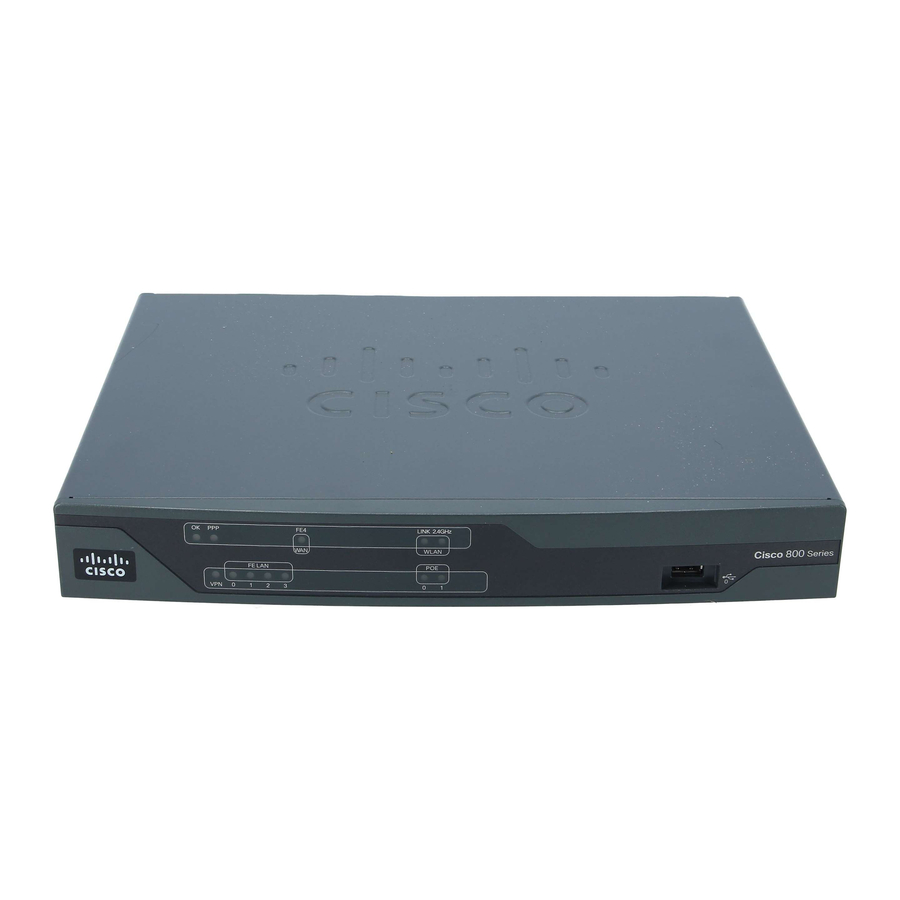
Cisco 866VAE, Cisco 867VAE, Cisco 866VAE-K9, and Cisco 867VAE-K9 integrated services routers (ISRs). Figure 1-3 Front Panel of the Cisco 860VAE series ISR Cisco 860 Series LEDs Cisco 860 Series, Cisco 880 Series, and Cisco 890 Series Integrated Services Routers Hardware Installation Guide OL-16215-10... - Page 21 Ethernet LAN GE and FE interfaces (GE0 Reset button interface and FE0 through FE3 interfaces) USB port Kensington security slot Serial port—console or auxiliary Cisco 860 Series, Cisco 880 Series, and Cisco 890 Series Integrated Services Routers Hardware Installation Guide OL-16215-10...
-
Page 22: Cisco 880 Series Isrs
Figure 1-9 show the features available on Cisco 880 series data routers. Some of the features shown may not be available on your router. Depending on the router model, the primary WAN port can be G.SHDSL, VDSLoPOTS, VDSL/ADSL over ISDN, VDSL/ADSL over POTS, or 10/100 FE. See the... - Page 23 The primary WAN port is designed for an RJ-45 connector only. Damage to the primary WAN Caution port may occur if a non-RJ-45 connector is inserted. Cisco 860 Series, Cisco 880 Series, and Cisco 890 Series Integrated Services Routers Hardware Installation Guide OL-16215-10...
- Page 24 WAN port may occur if a non-RJ-45 connector is inserted. Figure 1-9 shows the back panel details of the Cisco 888W data router. Nonwireless routers do not have antennas on the back panel. However, the feature locations are similar across all Cisco 880 series data routers. Figure 1-9...
-
Page 25: Cisco 880 Series Voice And Data Routers
Serial port—console or auxiliary 1. The Cisco 880 series ISRs can include an optional PoE module that provides power to 802.3af-compliant devices connected to ethernet ports 0 and 1. If this feature was not configured with the factory order, you must order and install it to enable the PoE function. - Page 26 Cisco 881 SRST and Cisco 888 SRST wireless voice router. Figure 1-10 Front Panel of the Cisco 881 SRST and Cisco 888 SRST Wireless Voice Router LEDs USB port Cisco 860 Series, Cisco 880 Series, and Cisco 890 Series Integrated Services Routers Hardware Installation Guide 1-10 OL-16215-10...
- Page 27 6. Ports 0 and 1 provide PoE with the optional PoE module installed. 7. The Cisco 880 series ISRs can include an optional PoE module that provides power to 802.3af-compliant devices connected to ethernet ports 0 and 1. If this feature was not configured with the factory order, SKU 800-IL-PM-2, you must order and install it to enable the PoE function.
- Page 28 2. Ports 0 and 1 provide PoE with the optional PoE module installed. 3. The Cisco 880 series ISRs can include an optional PoE module that provides power to 802.3af-compliant devices connected to ethernet ports 0 and 1. If this feature was not configured with the factory order, SKU 800-IL-PM-2, you must order and install it to enable the PoE function.
-
Page 29: Cisco 881-V, Cisco 887Va-V, And Cisco 887Va-V-W
The Cisco 881-V and Cisco 887VA-V voice and data series gives you the flexibility to use either FXS or BRI voice ports. However, the number of concurrent calls that can be supported by the router is limited by the codec complexity setting on the router. - Page 30 Figure 1-15 shows the back panel for the Cisco 881-V router. Figure 1-15 Back Panel of the Cisco 881-V Router C881 VOI CE Cisco 860 Series, Cisco 880 Series, and Cisco 890 Series Integrated Services Routers Hardware Installation Guide 1-14 OL-16215-10...
-
Page 31: Cisco 880 Series With Embedded Wlan Antennas
Figure 1-16 Front Panel of the C887VA-WD-A-K9 and C887VA-WD-E-K9 ISRs CD DATA LINK 2.4GHz 5GHz xDSL WLAN Cisco 800 Series FE LAN Cisco 860 Series, Cisco 880 Series, and Cisco 890 Series Integrated Services Routers Hardware Installation Guide 1-15 OL-16215-10... -
Page 32: C881Wd
LEDs only. All the ports are in the back panel. Figure 1-18 Front Panel of the C881WD-A-K9 and C881WD-E-K9 ISRs LINK 2.4GHz 5GHz WLAN Cisco 800 Series FE LAN Cisco 860 Series, Cisco 880 Series, and Cisco 890 Series Integrated Services Routers Hardware Installation Guide 1-16 OL-16215-10... -
Page 33: Cisco 890 Series Isrs
PoE function. Security feature card (SFC) socket • Cisco 860 Series, Cisco 880 Series, and Cisco 890 Series Integrated Services Routers Hardware Installation Guide 1-17 OL-16215-10... - Page 34 DIMM expansion socket that can accept up to 512 MB of additional memory, for a total of 768 MB • system memory in Cisco 891 and 892 series ISRs, and a total of 1 GB system memory in Cisco 892F series ISRs Three reverse-polarity threaded Neill-Concelman (RP-TNC) connectors on the back panel for •...
- Page 35 2. The Data BRI port is available only on the Cisco 892 router models. 3. The V.92 port (not shown) is available only on the Cisco 891 router models and is located between the console port and the Ethernet switch.
-
Page 36: Cisco 892Fsp, Cisco 896Va, Cisco 897Va, And Cisco 898Ea
Two 10/100/1000 GE ports for the Cisco 892FSP • One 10/100/1000 GE port for the Cisco 896VA, 897VA, and the Cisco 898EA. Either the SFP socket or the 10/100/1000 GE port can be active at a given time, but not both. - Page 37 10 Kensington security slot Figure 1-24 shows the front panel of the Cisco 892FSP router. Figure 1-24 Front Panel of the Cisco 892FSP Router LEDs Cisco 860 Series, Cisco 880 Series, and Cisco 890 Series Integrated Services Routers Hardware Installation Guide 1-21 OL-16215-10...
- Page 38 Cisco 896VA and the Cisco 897VA router. Figure 1-26 Front Panel of the Cisco 896VA and Cisco 897VA Router LEDs Cisco 860 Series, Cisco 880 Series, and Cisco 890 Series Integrated Services Routers Hardware Installation Guide 1-22 OL-16215-10...
- Page 39 GE WAN RESET 54VDC 1.2A 12VDC 2.5A 9 10 GE WAN interface On/Off switch SFP port Reset button USB port Earth ground connection Cisco 860 Series, Cisco 880 Series, and Cisco 890 Series Integrated Services Routers Hardware Installation Guide 1-23 OL-16215-10...
- Page 40 1. Port 0 through 3 can be configured as POE. POE is an optional feature for this model. If this feature was not configured with the factory order, you must order and install it to enable the PoE function. Cisco 860 Series, Cisco 880 Series, and Cisco 890 Series Integrated Services Routers Hardware Installation Guide 1-24...
- Page 41 1. Port 0 through 3 can be configured as POE. POE is an optional feature for this model. If this feature was not configured with the factory order, you must order and install it to enable the PoE function. Cisco 860 Series, Cisco 880 Series, and Cisco 890 Series Integrated Services Routers Hardware Installation Guide 1-25...
- Page 42 Figure 1-34 shows the front panel of the Cisco 898EA router. Figure 1-34 Front Panel of the Cisco 898EA Router LEDs Cisco 860 Series, Cisco 880 Series, and Cisco 890 Series Integrated Services Routers Hardware Installation Guide 1-26 OL-16215-10...
-
Page 43: Hardware Features
Cisco 860VAE Routers—Custom Configuration File On Cisco 860VAE routers, the reset button can be used to load a custom configuration file without having to use the CLI. The configuration file can be located on an external USB flash drive or on the router's compact flash. -
Page 44: Custom Configuration File For Cisco 892Fsp, 896Va, 897Va, And Cisco 898Ea
The priority for loading a configuration file is as follows: nvram: *.cfg Router flash: *.cfg If the router does not find a valid custom configuration file, the system aborts the process. Cisco 860 Series, Cisco 880 Series, and Cisco 890 Series Integrated Services Routers Hardware Installation Guide 1-28 OL-16215-10... - Page 45 Press and hold the Reset button until the system status LED begins to flash. Typically, this occurs within Step 2 5 seconds. The router reloads itself after the startup configuration has been replaced with the new customer configuration. Cisco 860 Series, Cisco 880 Series, and Cisco 890 Series Integrated Services Routers Hardware Installation Guide 1-29 OL-16215-10...
-
Page 46: Leds
Fast blinking—Data is either being received or being transmitted. Off—Radio is shut down, and no SSID is configured. Cisco 860 Series, Cisco 880 Series, and Cisco 890 Series Integrated Services Routers Hardware Installation Guide 1-30 OL-16215-10... - Page 47 Chapter 1 Product Overview Hardware Features Table 1-4 LED Descriptions for the Cisco 860 Series, Cisco 880 Series, and Cisco 890 Series ISRs (continued) Color Description 860 Series 880 Series 890 Series WLAN (5 GHz) Green On—Radio is connected, SSID is configured, and client is —...
- Page 48 Chapter 1 Product Overview Hardware Features Table 1-4 LED Descriptions for the Cisco 860 Series, Cisco 880 Series, and Cisco 890 Series ISRs (continued) Color Description 860 Series 880 Series 890 Series Data BRI B2 Green Blinking—B2 channel is receiving or sending data, or —...
- Page 49 “OFF,” or no cable attached to DSL connector. Off—Device is powered off or GE WAN mode is selected. Cisco 860 Series, Cisco 880 Series, and Cisco 890 Series Integrated Services Routers Hardware Installation Guide 1-33...
- Page 50 1. xDSL = General term referring to various forms of DSL, including ADSL (asymmetric digital subscriber line) and VDSL (very-high-data-rate digital subscriber line). Cisco 860 Series, Cisco 880 Series, and Cisco 890 Series Integrated Services Routers Hardware Installation Guide 1-34...
-
Page 51: Shared Leds On The Cisco 881-V And Cisco 887Va-V Voice And Data Routers
Shared LEDs on the Cisco 881-V and Cisco 887VA-V Voice and Data Routers On the Cisco 881-V, Cisco 887VA-V, and Cisco 887VA-V-W routers, the BRI1, BRI2 and the FXS ports share LED indicators. The following ports share an LED indicator: •... -
Page 52: Memory
Close-up of the BRI and FXS LED Indicators Memory The Cisco 860 series, 880 series, and 890 series routers contain flash memory and main memory. Flash Memory The Cisco 860 series, 880 series, and 890 series ISRs use non-upgradable flash memory storage. The onboard flash memory contains the Cisco IOS software image, the boot flash contains the ROMMON boot code, and a separate non-volatile flash contains the cookie configuration. -
Page 53: Usb Port
The fans spin at full speed, as a diagnostic aid, immediately after the router is powered up. After the router has booted, the fans spin as fast as necessary to minimize fan noise while maintaining a safe internal operating temperature. Cisco 860 Series, Cisco 880 Series, and Cisco 890 Series Integrated Services Routers Hardware Installation Guide 1-37 OL-16215-10... -
Page 54: Power Supply
The Cisco 890 series ISRs can include an optional PoE module that provides power to 802.3af-compliant devices connected to FE ports 0, 1, 2, and 3. The PoE module is an option available only for the Cisco 880 series and 890 series ISRs and requires a 48 V external power adapter. -
Page 55: Wireless Lan Connectivity
To configure the wireless device, use the Cisco IOS command-line interface (CLI). Table 1-10 describes the radios and antennas for the Cisco 860 series, 880 series, and 890 series routers. Cisco 860VAE ISRs do not support wireless LAN connectivity. Note The 5-GHz radio operates in the Unlicensed National Information Infrastructure (UNII) 1, 2, 3, 5-GHz frequency bands. -
Page 56: Supported Cisco Radio Antennas
Chapter 1 Product Overview Hardware Features Supported Cisco Radio Antennas The Cisco 891, Cisco 892, and Cisco 892F come with three removable dipole antennas that can be replaced using the Cisco approved antenna extenders listed in Table 1-11. Cisco supports only the antennas listed in Table 1-11 with the Cisco 890 series dual-band radio module. -
Page 57: Feature Summary
892F modem, or router. The router is capable of bridging and multiprotocol routing between the LAN and WAN ports. Cisco 860 Series, Cisco 880 Series, and Cisco 890 Series Integrated Services Routers Hardware Installation Guide 1-41 OL-16215-10... - Page 58 Chapter 1 Product Overview Hardware Features Table 1-12 Hardware Features Available in Cisco 860 Series, Cisco 880 Series, and Cisco 890 Series ISRs (continued) Feature Description 860 Series 880 Series 890 Series GE WAN port 10/100/1000 GE WAN Port. 866VAE, —...
- Page 59 Chapter 1 Product Overview Hardware Features Table 1-12 Hardware Features Available in Cisco 860 Series, Cisco 880 Series, and Cisco 890 Series ISRs (continued) Feature Description 860 Series 880 Series 890 Series Dying gasp Detects when the router is losing power, and sends a...
- Page 60 18. FXO = Foreign Exchange Office. 19. FXS = Foreign Exchange Station. 20. DID = Direct Inward Dialing. 21. SFP = small-form-factor pluggable. Cisco 860 Series, Cisco 880 Series, and Cisco 890 Series Integrated Services Routers Hardware Installation Guide 1-44 OL-16215-10...
-
Page 61: Chapter 2 Installing The Router
U.S.:NFPA 70, National Electrical Code, Article 810, Canada: Canadian Electrical Code, Section 54). Statement 1052 No user-serviceable parts inside. Do not open. Statement 1073 Warning Cisco 860 Series, Cisco 880 Series, and Cisco 890 Series Integrated Services Routers Hardware Installation Guide OL-16215-10... -
Page 62: Equipment, Tools, And Connections
AC power supply cable with cable retention clip Cisco Configuration Professional (Cisco CP) CD 1. By default, no cables are shipped with Cisco 860VAE models unless requested through the dynamic configuration tool. 2. DSL = digital subscriber line. 3. Shipped with Cisco 867 models only. -
Page 63: Connections
Installing the Router This section describes how to install the Cisco 860 series, 880 series, and 890 series ISRs. These routers can either be installed on a table top or other flat horizontal surface or be mounted on a wall. The Cisco 890 series ISRs may be mounted in a rack. -
Page 64: Warnings
The Cisco 890 series wireless routers have three reverse-polarity threaded Neill-Concelman (RP-TNC) connectors on the back panel. The antennas that are shipped with the router are dual-band 2.4-GHz to 5-GHz omnidirectional dipole antennas. Cisco 860 Series, Cisco 880 Series, and Cisco 890 Series Integrated Services Routers Hardware Installation Guide OL-16215-10... - Page 65 All wireless LAN products in the 5.2/5.3GHz band cannot be used outdoors. Use the product only Warning indoors. Statement 372 Before you install the Cisco 890 series wireless router on a table, wall, or rack, connect the antennas to Note the back panel. It is difficult to attach the antennas after the router is installed.
- Page 66 Chapter 2 Installing the Router Installing the Router Figure 2-2 Antennas Oriented Vertically Up Cisco 860 Series, Cisco 880 Series, and Cisco 890 Series Integrated Services Routers Hardware Installation Guide OL-16215-10...
-
Page 67: Installing On A Table
Connect the chassis to a reliable earth ground. For the chassis ground connection procedures, see the “Installing the Router Ground Connection” section on page 2-13. Do not place anything on top of the router. Note Cisco 860 Series, Cisco 880 Series, and Cisco 890 Series Integrated Services Routers Hardware Installation Guide OL-16215-10... -
Page 68: Mounting On A Wall
Installing the Router Mounting on a Wall The Cisco 860 series, 880 series, and 890 series ISRs have mounting holes on the bottom of the chassis for mounting the unit on a wall or other vertical surface. The mounting holes are bidirectional. You can hang the router with the front bezel facing upward or downward. - Page 69 Hang the router on the screw without forcibly pushing towards the wall side. The screw head may Step 3 damage the protection wall inside. Place the power adapter on a nearby horizontal surface. See Figure 2-5. Cisco 860 Series, Cisco 880 Series, and Cisco 890 Series Integrated Services Routers Hardware Installation Guide OL-16215-10...
- Page 70 Connect the chassis to a reliable earth ground. For the chassis ground connection procedures, see the Step 4 “Installing the Router Ground Connection” section on page 2-13. Cisco 860 Series, Cisco 880 Series, and Cisco 890 Series Integrated Services Routers Hardware Installation Guide 2-10 OL-16215-10...
-
Page 71: Installing In A Rack
Installing the Router Installing the Router Installing in a Rack The Cisco 890 series ISRs can be mounted in a rack. To install a Cisco 890 series ISR in a rack, follow these steps: Remove the screws, as shown in Figure 2-6. - Page 72 Statement 1006 Using two screws for each side (supplied with the rack), attach the Cisco 890 series ISR with rack-mount Step 3 brackets to a 19-inch rack. Start with the lower pair of screws first, resting the brackets on the lower screws while you insert the upper pair of screws.
-
Page 73: Installing The Router Ground Connection
After you install and properly ground the router, you can connect the power wiring, the WAN and LAN cables, and the cables for administrative access as required for your installation. Cisco 860 Series, Cisco 880 Series, and Cisco 890 Series Integrated Services Routers Hardware Installation Guide 2-13... -
Page 74: Installing The Fips Cover
Perform the following steps to install the FIPS cover in the router: Remove the four mounting screws of the top cover. Step 1 Cisco 860 Series, Cisco 880 Series, and Cisco 890 Series Integrated Services Routers Hardware Installation Guide 2-14 OL-16215-10... - Page 75 Rotate and bring into the close position to hinge to the correct hexagon. Step 3 Place the adapter plate before closing by aligning the mounting holes. Step 4 Cisco 860 Series, Cisco 880 Series, and Cisco 890 Series Integrated Services Routers Hardware Installation Guide 2-15 OL-16215-10...
- Page 76 Install the right-side FIPS cover the same way as the left-side FIPS cover. Step 6 View after both covers are installed. Step 7 Cisco 860 Series, Cisco 880 Series, and Cisco 890 Series Integrated Services Routers Hardware Installation Guide 2-16 OL-16215-10...
- Page 77 If the FIPS covers are installed with the rack mount brackets, the adapter plates are not required in the Step 8 installation. Cisco 860 Series, Cisco 880 Series, and Cisco 890 Series Integrated Services Routers Hardware Installation Guide 2-17 OL-16215-10...
- Page 78 Chapter 2 Installing the Router Installing the Router Cisco 860 Series, Cisco 880 Series, and Cisco 890 Series Integrated Services Routers Hardware Installation Guide 2-18 OL-16215-10...
-
Page 79: Connecting The Router
C H A P T E R Connecting the Router This chapter describes how to connect Cisco 860 series, Cisco 880 series, and Cisco 890 series Integrated Services Routers (ISRs) to Ethernet devices, Power over Ethernet (PoE), and a network. The... -
Page 80: Safety Warnings
Statement 1026 Warning Only trained and qualified personnel should be allowed to install, replace, or service this equipment. Statement 1030 Cisco 860 Series, Cisco 880 Series, and Cisco 890 Series Integrated Services Routers Hardware Installation Guide OL-16215-10... - Page 81 No user-serviceable parts inside. Do not open. Statement 1073 Warning Warning Installation of the equipment must comply with local and national electrical codes. Statement 1074 Cisco 860 Series, Cisco 880 Series, and Cisco 890 Series Integrated Services Routers Hardware Installation Guide OL-16215-10...
-
Page 82: Preparing To Connect The Router
“Technical Specifications” section on page A-1 for cabling specifications. If this appendix does not provide specifications for a particular cable, we strongly recommend ordering the cable from Cisco. Cisco 860 Series, Cisco 880 Series, and Cisco 890 Series Integrated Services Routers Hardware Installation Guide OL-16215-10... -
Page 83: Connecting A Pc, Server, Or Workstation
Step 3 Use the Cisco Configuration Express to configure the Internet connection settings. See Note Cisco Configuration Professional Quick Start Guide for more information. Cisco 860 Series, Cisco 880 Series, and Cisco 890 Series Integrated Services Routers Hardware Installation Guide OL-16215-10... -
Page 84: Connecting A Phone
Figure 3-2 Connecting a Phone PQRS WXYZ OPER Yellow Ethernet cable RJ-45 port on a phone Ethernet switch port 1 on the router Cisco 860 Series, Cisco 880 Series, and Cisco 890 Series Integrated Services Routers Hardware Installation Guide OL-16215-10... -
Page 85: Connecting An External Ethernet Switch
Connect the other end of the cable to the available port on the Ethernet switch to add additional Ethernet Step 2 connections. Turn on the Ethernet switch. Step 3 Cisco 860 Series, Cisco 880 Series, and Cisco 890 Series Integrated Services Routers Hardware Installation Guide OL-16215-10... -
Page 86: Connecting The V.92 Modem Port
Connect one end of the straight-through R-J11 cable to the V.92 port. Step 1 Connect the other end of the straight through R-J11 cable to an RJ-11 telephone wall outlet. Step 2 Cisco 860 Series, Cisco 880 Series, and Cisco 890 Series Integrated Services Routers Hardware Installation Guide OL-16215-10... -
Page 87: Connecting A Terminal Or Pc To The Console Port
Some laptops and PCs do not come with DB-9 serial port connectors and may require a Note USB-to-serial port adapter. To communicate with the router, start a terminal emulator application. Step 3 Cisco 860 Series, Cisco 880 Series, and Cisco 890 Series Integrated Services Routers Hardware Installation Guide OL-16215-10... -
Page 88: Terminal Emulator Settings
Connecting a Modem to the Aux Port Aux port (RJ-45) DB-9 to DB-25 modem adapter (if required) Light blue console cable Modem Cisco 860 Series, Cisco 880 Series, and Cisco 890 Series Integrated Services Routers Hardware Installation Guide 3-10 OL-16215-10... -
Page 89: Connecting The 3G Card
Global System for Mobile Communications (GSM) customers need to insert a SIM card, Note provided by their network carrier, into the 3G card. Cisco 860 Series, Cisco 880 Series, and Cisco 890 Series Integrated Services Routers Hardware Installation Guide 3-11 OL-16215-10... - Page 90 Figure 3-8. Step 2 Figure 3-8 Opening the Anti-theft Locking Bracket Front View Back View Pins on the locking bracket for alignment Cisco 860 Series, Cisco 880 Series, and Cisco 890 Series Integrated Services Routers Hardware Installation Guide 3-12 OL-16215-10...
- Page 91 Figure 3-9 Installing the Locking Bracket 3G card Notch on the 3G card Locking bracket Cisco 860 Series, Cisco 880 Series, and Cisco 890 Series Integrated Services Routers Hardware Installation Guide 3-13 OL-16215-10...
- Page 92 To connect the antenna to the 3G card, insert the antenna connector into the antenna connector receptacle Step 6 on the 3G card. Cisco 860 Series, Cisco 880 Series, and Cisco 890 Series Integrated Services Routers Hardware Installation Guide 3-14 OL-16215-10...
- Page 93 1. The antenna connector receptacle is located on either the left, right or front of the card for different SKUs. Please locate the receptacle of your card before plugging in the cable. Cisco 860 Series, Cisco 880 Series, and Cisco 890 Series Integrated Services Routers Hardware Installation Guide 3-15...
- Page 94 PCEX-3G-CDMA-V, PCEX-3G-CDMA-B, CISCO881G-A-K9, CISCO881G-S-K9, CISCO881G-V-K9 Clean the flat surface to which you will affix the antenna. Step 7 Cisco 860 Series, Cisco 880 Series, and Cisco 890 Series Integrated Services Routers Hardware Installation Guide 3-16 OL-16215-10...
-
Page 95: Installing The 3G Adapter For Extended Cable/Antenna
Figure 3-14 Locating the Phillips Screw Phillips screw on the left side of router Air vent holes to be aligned with adapter Cisco 860 Series, Cisco 880 Series, and Cisco 890 Series Integrated Services Routers Hardware Installation Guide 3-17 OL-16215-10... - Page 96 Align and insert the hooks of the adapter into the air vent holes on the left side router body as shown in Figure 3-16. Figure 3-16 Inserting the Hooks Hooks aligned and inserted into the router. Cisco 860 Series, Cisco 880 Series, and Cisco 890 Series Integrated Services Routers Hardware Installation Guide 3-18 OL-16215-10...
- Page 97 Step 1 and use the screw to attach the adapter to the router as shown in Figure 3-17. Figure 3-17 Attaching the Adapter Cisco 860 Series, Cisco 880 Series, and Cisco 890 Series Integrated Services Routers Hardware Installation Guide 3-19 OL-16215-10...
- Page 98 Table 3-2 lists the loss information for the ultra-low-loss (ULL) LMR 400 cables available with the adpater for the 3G fixed platforms. Cisco 860 Series, Cisco 880 Series, and Cisco 890 Series Integrated Services Routers Hardware Installation Guide 3-20 OL-16215-10...
-
Page 99: Connecting A Data Bri Port
Although the following procedure shows a Cisco 888W data router, this procedure applies to all Cisco 880 series router with a Data BRI port. Cisco 860 Series, Cisco 880 Series, and Cisco 890 Series Integrated Services Routers Hardware Installation Guide 3-21... - Page 100 Connect the second unshielded Category 5 cable from the telecommunication service port on the splitter Step 4 to the wall jack to allow a link to the network service provider. Cisco 860 Series, Cisco 880 Series, and Cisco 890 Series Integrated Services Routers Hardware Installation Guide 3-22 OL-16215-10...
-
Page 101: Connecting An Fe Line To An Fe Wan Port
Modem connected to the Internet CAT 5 cable Connect the other end of cable to an available port on the modem. Step 2 Cisco 860 Series, Cisco 880 Series, and Cisco 890 Series Integrated Services Routers Hardware Installation Guide 3-23 OL-16215-10... -
Page 102: Connecting A Ge Line To An Ge Wan Port
Modem connected to the Internet CAT 5 cable Connect the other end of cable to an available port on the modem. Step 2 Cisco 860 Series, Cisco 880 Series, and Cisco 890 Series Integrated Services Routers Hardware Installation Guide 3-24 OL-16215-10... -
Page 103: Connecting An Xdsl Line
There is the danger of explosion if the battery is replaced incorrectly. Replace the battery only with the same or equivalent type recommended by the manufacturer. Dispose of used batteries according to the manufacturer’s instructions. Statement 1015 Cisco 860 Series, Cisco 880 Series, and Cisco 890 Series Integrated Services Routers Hardware Installation Guide 3-25 OL-16215-10... - Page 104 G.SHDSL port, VDSL2oPOTs port, or DSL wall jack ADSL2+ port Connect the other end of the cable to the DSL wall jack. Step 2 Cisco 860 Series, Cisco 880 Series, and Cisco 890 Series Integrated Services Routers Hardware Installation Guide 3-26 OL-16215-10...
-
Page 105: Connecting Power Over Ethernet
48-VDC Power over Ethernet (PoE) power adapter to your router. The PoE adapter provides power to ports 0 and 1 of the 4-port 10/100 FE switch on the Cisco 880 series routers and ports 0,1, 2, and 3 of the 8-port 10/100 FE switch on the Cisco 890 series routers. -
Page 106: Connecting The Ac Adapter
The Cisco 892FSP utilizes a single 4-pin power connector type. Figure 3-27 shows the pin number Note assignment of the Cisco 892FSP Power Adapter Connector. Cisco 860 Series, Cisco 880 Series, and Cisco 890 Series Integrated Services Routers Hardware Installation Guide 3-28 OL-16215-10... - Page 107 Connecting the Router Connecting the AC Adapter To connect your Cisco 860 series, Cisco 880 series, or the Cisco 890FSP ISR to an AC power outlet, follow these steps: Connect the router to an AC power outlet as shown in Figure 3-25.To connect the Cisco 892FSP router,...
- Page 108 Pin 3 Pin 2 Pin 1 Pin 1 Pin 3 Ground +12 V Pin 2 Pin 4 1. NC = No Connection. Cisco 860 Series, Cisco 880 Series, and Cisco 890 Series Integrated Services Routers Hardware Installation Guide 3-30 OL-16215-10...
- Page 109 Figure 3-28 Securing the Power Cord Power lock clip DC plug Power cord Lock holes on either side of the power connector Cisco 860 Series, Cisco 880 Series, and Cisco 890 Series Integrated Services Routers Hardware Installation Guide 3-31 OL-16215-10...
-
Page 110: Connecting An Fxs Line
ON. To avoid electric shock, use caution when working near WAN ports. When detaching cables, detach the end away from the unit first. Statement 1026 Cisco 860 Series, Cisco 880 Series, and Cisco 890 Series Integrated Services Routers Hardware Installation Guide 3-32... - Page 111 RJ-11 port RJ-11 cable Step 2 Connect the other end of the cable to the RJ-11 port on the fax machine or telephone. Cisco 860 Series, Cisco 880 Series, and Cisco 890 Series Integrated Services Routers Hardware Installation Guide 3-33 OL-16215-10...
-
Page 112: Connecting An Fxo Line
Connecting an FXO Line FXO port Telephone outlet RJ-11 cable Connect the other end of the RJ-11 cable to a telephone wall outlet. Step 2 Cisco 860 Series, Cisco 880 Series, and Cisco 890 Series Integrated Services Routers Hardware Installation Guide 3-34 OL-16215-10... -
Page 113: Connecting A Voice Isdn Bri Line
Step 1 When the interface is configured as NT and is connecting to a TE device, use a crossover cable. Note Table A-13. Cisco 860 Series, Cisco 880 Series, and Cisco 890 Series Integrated Services Routers Hardware Installation Guide 3-35 OL-16215-10... - Page 114 Voice BRI port Telephone outlet RJ-45 cable Connect the other end of the cable to the RJ-45 telephone outlet or other device. Step 2 Cisco 860 Series, Cisco 880 Series, and Cisco 890 Series Integrated Services Routers Hardware Installation Guide 3-36 OL-16215-10...
-
Page 115: Connecting A Small Form-Factor Pluggable Module
Statement 1056 Use of controls, adjustments, or performing procedures other than those specified may result in Warning hazardous radiation exposure. Statement 1057 Cisco 860 Series, Cisco 880 Series, and Cisco 890 Series Integrated Services Routers Hardware Installation Guide 3-37 OL-16215-10... -
Page 116: Installing An Sfp Module
SFP model or technology type. For information on the SFP technology type and model, see the label on the side of the SFP. Cisco 860 Series, Cisco 880 Series, and Cisco 890 Series Integrated Services Routers Hardware Installation Guide 3-38... -
Page 117: Online Insertion And Removal
For a 1000 base SFP, the speed is set to 1000 and duplex is set to full. Cisco 860 Series, Cisco 880 Series, and Cisco 890 Series Integrated Services Routers Hardware Installation Guide... -
Page 118: Verifying Connections
To PPP clients Green when either a PPPoE or PPPoA client is running. To VPN tunnel Green when a crypto session is running. Cisco 860 Series, Cisco 880 Series, and Cisco 890 Series Integrated Services Routers Hardware Installation Guide 3-40 OL-16215-10... - Page 119 To LAN GE/FE line Blinking when there is LAN activity (traffic in either (860VAE models direction). only) Off when the link is down. Cisco 860 Series, Cisco 880 Series, and Cisco 890 Series Integrated Services Routers Hardware Installation Guide 3-41 OL-16215-10...
- Page 120 12. VPN = Virtual Private Network. 13. SSID = service set identifier. 14. PoE = Power over Ethernet. 15. SFP = small-form-factor pluggable. Cisco 860 Series, Cisco 880 Series, and Cisco 890 Series Integrated Services Routers Hardware Installation Guide 3-42 OL-16215-10...
-
Page 121: Chapter 4 Initial Configuration
Cisco Configuration Professional Express After you connect the cables and power up the router, we recommend that you use the Cisco CP Express web-based application to configure the initial router settings. For instructions on how to use Cisco CP Express to configure the router see Cisco CP Express User’s... -
Page 122: Cisco Configuration Professional Express
To continue using the Cisco IOS CLI for initial configuration, see the applicable configuration procedures in Cisco 860 Series, Cisco 880 Series, and Cisco 890 Series Integrated Services Routers Software Configuration Guide. Cisco 860 Series, Cisco 880 Series, and Cisco 890 Series Integrated Services Routers Hardware Installation Guide OL-16215-10... -
Page 123: Setup Command Facility
Cisco IOS Configuration Fundamentals Command Reference, Release 12.2T. To proceed using the setup command facility, enter yes. Step 3 Continue with configuration dialog? [yes/no]: yes Cisco 860 Series, Cisco 880 Series, and Cisco 890 Series Integrated Services Routers Hardware Installation Guide OL-16215-10... - Page 124 IP address for this interface: 172.1.2.3 Subnet mask for this interface [255.255.0.0] : 255.255.0.0 Class B network is 172.1.0.0, 26 subnet bits; mask is /16 Cisco 860 Series, Cisco 880 Series, and Cisco 890 Series Integrated Services Routers Hardware Installation Guide OL-16215-10...
-
Page 125: Verifying The Initial Configuration
“Verifying the Initial Configuration” section on page 4-5 Step 13 verification procedures. After the initial configuration file is created, you can use the Cisco IOS CLI to perform additional configuration. Verifying the Initial Configuration To verify that the new interfaces are operating correctly, perform the following tests: To verify that the interfaces and line protocol are in the correct state—up or down—enter the show... -
Page 126: Initial Configuration Of The Wireless Access Point
For information on how to do basic wireless configuration on your router see the “Basic Wireless Device” chapter of the Cisco 860 Series, Cisco 880, and Cisco 890 Series Integrated Services Routers Software Configuration Guide. Cisco 860 Series, Cisco 880 Series, and Cisco 890 Series Integrated Services Routers Hardware Installation Guide OL-16215-10... -
Page 127: Appendix
A P P E N D I X Technical Specifications This appendix provides router, port, and cabling specifications for the Cisco 860 series, Cisco 880 series, and Cisco 890 series Integrated Services Routers (ISRs). It contains the following sections: Router Specifications, page A-2 •... -
Page 128: Router Specifications
Input voltage 85 to 264 VAC not supported Input frequency 47 to 63 Hz Power output 80 W, maximum Output voltage –48 VDC Cisco 860 Series, Cisco 880 Series, and Cisco 890 Series Integrated Services Routers Hardware Installation Guide OL-16215-10... -
Page 129: Wireless Access Point
FE ports 0, 1, 2, and 3. Table A-3 Ethernet FE LAN Port Pinouts Function RX– PoE—optional PoE—optional TX– PoE—optional PoE—optional Cisco 860 Series, Cisco 880 Series, and Cisco 890 Series Integrated Services Routers Hardware Installation Guide OL-16215-10... -
Page 130: Console And Auxiliary Port Connector Pinouts
Table A-5 lists the pinouts for the console and auxiliary port connectors. Table A-5 Console and Auxiliary Port Connector Pinouts RJ-45 Pin Function Cisco 860 Series, Cisco 880 Series, and Cisco 890 Series Integrated Services Routers Hardware Installation Guide OL-16215-10... -
Page 131: Fxs And Fxo Port Connector Pinouts
ADSL2+ Port Connector Pinouts Table A-8 lists the ADSL2+ connector pinouts. Table A-8 ADSL2+ Connector Pinouts (RJ-11) RJ-11 Pin Function Unused Unused RING Unused Unused Cisco 860 Series, Cisco 880 Series, and Cisco 890 Series Integrated Services Routers Hardware Installation Guide OL-16215-10... -
Page 132: V.92 Port Connector Pinouts
C888E • • C888EW • C888EA Table A-11 G.SHDSL WAN Port Pinouts for Four-Pair Products Function TIP (Port1) RING (Port1) TIP (Port2) Cisco 860 Series, Cisco 880 Series, and Cisco 890 Series Integrated Services Routers Hardware Installation Guide OL-16215-10... -
Page 133: Data Bri Port Connector Pinouts
Pin 5/R- Pin 6/T- Pin 6/R- Pin 6/T- 1. Use a straight-through cable for NT interfaces. 2. Use a crossover cable for TE interfaces. Cisco 860 Series, Cisco 880 Series, and Cisco 890 Series Integrated Services Routers Hardware Installation Guide OL-16215-10... -
Page 134: Sfp Port Connector Pinouts
Straight-through cable Crossover cable • Because of the autocrossover (autosensing) function, both straight-through and crossover cables can be used for the Ethernet LAN port. Cisco 860 Series, Cisco 880 Series, and Cisco 890 Series Integrated Services Routers Hardware Installation Guide OL-16215-10... -
Page 135: Ethernet Cable Specifications
The maximum length for the Ethernet cables that connect equipment to the router is 328 feet (100 meters). This length is also the maximum distance between the router and the equipment connected to it. Cisco 860 Series, Cisco 880 Series, and Cisco 890 Series Integrated Services Routers Hardware Installation Guide OL-16215-10... - Page 136 Appendix A Technical Specifications Cable Specifications Cisco 860 Series, Cisco 880 Series, and Cisco 890 Series Integrated Services Routers Hardware Installation Guide A-10 OL-16215-10...