Cisco 860 Series Hardware Installation Manual
Integrated services routers
Hide thumbs
Also See for 860 Series:
- Hardware installation manual (136 pages) ,
- Installing manual (60 pages) ,
- Quick reference manual (3 pages)
Table of Contents
Advertisement
Cisco 860 Series, Cisco 880 Series, and Cisco 890
Series Integrated Services Routers Hardware
Installation Guide
Americas Headquarters
Cisco Systems, Inc.
170 West Tasman Drive
San Jose, CA 95134-1706
USA
http://www.cisco.com
Tel:
408 526-4000
800 553-NETS (6387)
Fax: 408 527-0883
Text Part Number: OL-16193-07
Advertisement
Chapters
Table of Contents

Related Manuals for Cisco 860 Series


Summary of Contents for Cisco 860 Series
- Page 1 Cisco 860 Series, Cisco 880 Series, and Cisco 890 Series Integrated Services Routers Hardware Installation Guide Americas Headquarters Cisco Systems, Inc. 170 West Tasman Drive San Jose, CA 95134-1706 http://www.cisco.com Tel: 408 526-4000 800 553-NETS (6387) Fax: 408 527-0883 Text Part Number: OL-16193-07...
- Page 2 Modifications to this product not authorized by Cisco Systems, Inc. could void the FCC approval and negate your authority to operate the product. The Cisco implementation of TCP header compression is an adaptation of a program developed by the University of California, Berkeley (UCB) as part of UCB’s public domain version of the UNIX operating system.
- Page 3 This guide provides an overview and explains how to install, connect, and perform initial configuration for the wireless and nonwireless Cisco 860 series, Cisco 880 series, and Cisco 890 series Integrated Services Routers (ISRs). Some information may not apply to your particular router model.
- Page 4 Means the following information will help you solve a problem. The tip information might not be troubleshooting or even an action, but could be useful information. Cisco 860 Series, Cisco 880 Series, and Cisco 890 Series Integrated Services Routers Hardware Installation Guide Name Chapter 1, “Product Overview”...
- Page 5 Ende jeder Warnung angegebenen Anweisungsnummer nach der jeweiligen Übersetzung in den übersetzten Sicherheitshinweisen, die zusammen mit diesem Gerät ausgeliefert wurden. BEWAHREN SIE DIESE HINWEISE GUT AUF. Cisco 860 Series, Cisco 880 Series, and Cisco 890 Series Integrated Services Routers Hardware Installation Guide OL-16193-07...
- Page 6 översättning i de översatta säkerhetsvarningar som medföljer denna anordning. SPARA DESSA ANVISNINGAR Cisco 860 Series, Cisco 880 Series, and Cisco 890 Series Integrated Services Routers Hardware Installation Guide Preface OL-16193-07...
- Page 7 Preface Cisco 860 Series, Cisco 880 Series, and Cisco 890 Series Integrated Services Routers Hardware Installation Guide OL-16193-07...
- Page 8 Brug erklæringsnummeret efter hver advarsel for at finde oversættelsen i de oversatte advarsler, der fulgte med denne enhed. GEM DISSE ANVISNINGER Cisco 860 Series, Cisco 880 Series, and Cisco 890 Series Integrated Services Routers Hardware Installation Guide viii OL-16193-07...
- Page 9 Preface Cisco 860 Series, Cisco 880 Series, and Cisco 890 Series Integrated Services Routers Hardware Installation Guide OL-16193-07...
- Page 10 Avoid using a telephone (other than a cordless type) during an electrical storm. There may be a Warning remote risk of electric shock from lightning. Statement 1038 Cisco 860 Series, Cisco 880 Series, and Cisco 890 Series Integrated Services Routers Hardware Installation Guide Preface OL-16193-07...
- Page 11 Read the installation instructions before connecting the system to the power source. Statement Warning 1004 Ultimate disposal of this product should be handled according to all national laws and Warning regulations. Statement 1040 Cisco 860 Series, Cisco 880 Series, and Cisco 890 Series Integrated Services Routers Hardware Installation Guide OL-16193-07...
-
Page 12: Related Documentation
Related Documentation In addition to the Cisco 860 series, Cisco 880 series, and Cisco 890 series ISR Hardware Installation Guide (this document), the Cisco 860 series, Cisco 880 series, and Cisco 890 series ISR documentation set includes the following documents: Regulatory Compliance and Safety Information for Cisco 800 Series and SOHO Series Routers •... - Page 13 The RSS feeds are a free service and Cisco currently supports RSS version 2.0. Cisco 860 Series, Cisco 880 Series, and Cisco 890 Series Integrated Services Routers Hardware Installation Guide xiii...
- Page 14 Preface Cisco 860 Series, Cisco 880 Series, and Cisco 890 Series Integrated Services Routers Hardware Installation Guide OL-16193-07...
-
Page 15: Product Overview
Some illustrations in this document show a wireless router. Both wireless and nonwireless models are Note available in the Cisco 860 series, Cisco 880 series, and Cisco 890 series ISRs. Port and feature locations are similar for both wireless and nonwireless routers. -
Page 16: Cisco 860 Series Isrs
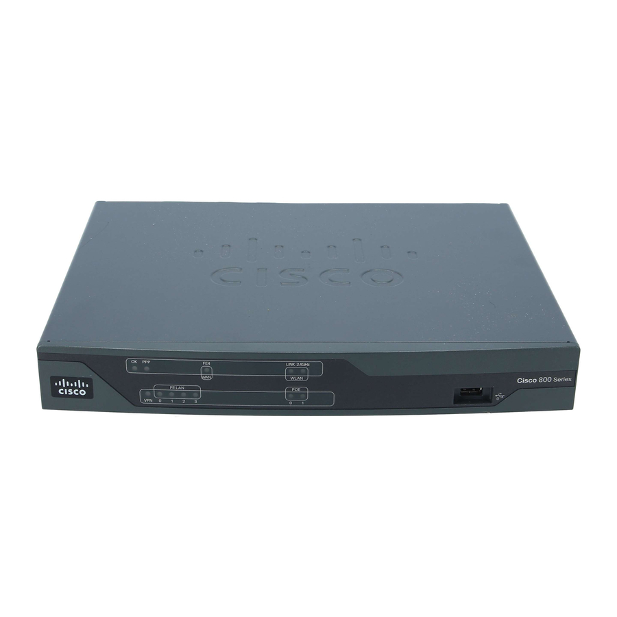
Cisco 860 Series ISRs The Cisco 860 series, Cisco 880 series, and Cisco 890 series ISRs have a desktop form factor with built-in wall-mount features. The Cisco 890 series ISRs also have optional rack-mount features. These ISRs are powered by an external power supply adapter. The various models differ in the WAN interface and features that they support. -
Page 17: Cisco 860Vae Series Isrs
Product Overview Figure 1-2 shows the back panel details of the Cisco 861 wireless (861W) ISR. Nonwireless routers do not have antennas on the back panel. However, the feature locations are similar for all Cisco 860 series routers. Figure 1-2 FE 4 Primary WAN port—10/100... -
Page 18: Ios Images
Cisco 867VAE-K9 integrated services routers (ISRs). Figure 1-3 Cisco 860 Series LEDs Cisco 860 Series, Cisco 880 Series, and Cisco 890 Series Integrated Services Routers Hardware Installation Guide Interfaces of the Cisco 860VAE Series ISRs 866VAE — IOS Images of the Cisco 860VAE Series ISRs 866VAE —... -
Page 19: Cisco 880 Series Isrs
Cisco 880 Series ISRs The Cisco 880 series ISRs have data and voice capabilities. They have the following features: Cisco 860 Series, Cisco 880 Series, and Cisco 890 Series Integrated Services Routers Hardware Installation Guide OL-16193-07 Back Panel of the Cisco 866VAE ISR... -
Page 20: Cisco 880 Series Data Routers
Cisco 880 series data routers. Some of the features shown may not be available on your router. Cisco 860 Series, Cisco 880 Series, and Cisco 890 Series Integrated Services Routers Hardware Installation Guide Chapter 1 Product Overview... - Page 21 4-port 10/100 Ethernet switch Serial port—console or auxiliary PoE power connector—optional Cisco 860 Series, Cisco 880 Series, and Cisco 890 Series Integrated Services Routers Hardware Installation Guide OL-16193-07 Front Panel of the Cisco 880 Series Wireless Data Router data sheet for supported vendors.
- Page 22 The primary WAN port is designed for an RJ-45 connector only. Damage to the primary WAN Caution port may occur if a non RJ-45 connector is inserted. Cisco 860 Series, Cisco 880 Series, and Cisco 890 Series Integrated Services Routers Hardware Installation Guide Back Panel of the Cisco 887VA and 887VA-M Router Chapter 1...
-
Page 23: Cisco 880 Series Voice And Data Routers
Foreign Exchange Station (FXS), Foreign Exchange Office (FXO), or BRI connections. Cisco 860 Series, Cisco 880 Series, and Cisco 890 Series Integrated Services Routers Hardware Installation Guide OL-16193-07 Back Panel of the Cisco 888W Data Router —G.SHDSL,... -
Page 24: Cisco 881 Srst And Cisco 888 Srst
Cisco 881 SRST and Cisco 888 SRST wireless voice router. Figure 1-10 Front Panel of the Cisco 881 SRST and Cisco 888 SRST Wireless Voice Router LEDs USB port Cisco 860 Series, Cisco 880 Series, and Cisco 890 Series Integrated Services Routers Hardware Installation Guide 1-10 OL-16193-07... - Page 25 0 and 1. If this feature was not configured with the factory order, SKU 800-IL-PM-2, you must order and install it to enable the PoE function. The PoE power supply, SKU 800-ILPM-4, is also required. Cisco 860 Series, Cisco 880 Series, and Cisco 890 Series Integrated Services Routers Hardware Installation Guide OL-16193-07 Back Panel of the Cisco C881SRST-W Voice Router —10/100 FE...
- Page 26 Flexible, Medium or High complexity. Cisco 860 Series, Cisco 880 Series, and Cisco 890 Series Integrated Services Routers Hardware Installation Guide 1-12 Back Panel of the Cisco C888SRST-W Voice —G.SHDSL...
- Page 27 Cisco 881-V, Cisco 887VA-V, and Cisco 887VA-V-W. Figure 1-13 LEDs Cisco 860 Series, Cisco 880 Series, and Cisco 890 Series Integrated Services Routers Hardware Installation Guide OL-16193-07 Maximum Number of Supported Calls Flexible Complexity...
- Page 28 Figure 1-15 Fast Ethernet WAN port Voice BRI ports Cisco 860 Series, Cisco 880 Series, and Cisco 890 Series Integrated Services Routers Hardware Installation Guide 1-14 Back Panel of the Cisco 887 VA-V Router C 887VA -W VO I C E...
-
Page 29: Cisco 890 Series Isrs
• The following feature is located on the front panel: Two USB 1.1 ports • Cisco 860 Series, Cisco 880 Series, and Cisco 890 Series Integrated Services Routers Hardware Installation Guide OL-16193-07 Cisco 890 Series ISRs Power connector Earth ground connection... - Page 30 RP-TNC connectors (wireless models only) Backup—Data BRI Primary WAN port—FE and GE Cisco 860 Series, Cisco 880 Series, and Cisco 890 Series Integrated Services Routers Hardware Installation Guide 1-16 Front Panel of the Cisco 890 Series Wireless ISR Back Panel of the Cisco 892-W Router or V.92...
-
Page 31: Hardware Features
Figure 1-18 SFP port Hardware Features This section provides an overview of the following hardware features for the Cisco 860 series, 880 series, and 890 series ISRs. A feature summary is available at the end of this section. Kensington Lock •... -
Page 32: Kensington Lock
To reset the router to the factory default configuration, follow these steps: Verify that IOS is running correctly by checking that the system status LED is on. Step 1 Cisco 860 Series, Cisco 880 Series, and Cisco 890 Series Integrated Services Routers Hardware Installation Guide 1-18 Chapter 1... - Page 33 Blinking—Data is either being received or being transmitted. Off—Port is not connected. Cisco 860 Series, Cisco 880 Series, and Cisco 890 Series Integrated Services Routers Hardware Installation Guide OL-16193-07 describes the LEDs for the Cisco 860 series, 880 series, and 890 series ISRs.
- Page 34 Hardware Features Table 1-4 LED Descriptions for the Cisco 860 Series, Cisco 880 Series, and Cisco 890 Series ISRs (continued) Color Description WLAN Green On—Radio is connected, SSID (2.4 GHz) is associated, but no data is being received or being transmitted.
- Page 35 Chapter 1 Product Overview Table 1-4 LED Descriptions for the Cisco 860 Series, Cisco 880 Series, and Cisco 890 Series ISRs (continued) Color Description Data BRI B1 Green Blinking—B1 channel is either receiving or sending data, or data is passing through ISDN channel 1.
- Page 36 Hardware Features Table 1-4 LED Descriptions for the Cisco 860 Series, Cisco 880 Series, and Cisco 890 Series ISRs (continued) Color Description Not present. Green Present and enabled. Amber Present with failure. SFP S Green Blinking—Blinking frequency indicates port speed.
- Page 37 For activity status on the BRI ISDN port, use the show isdn status command. • Figure 1-19 shows a close-up view of the LED indicators. Cisco 860 Series, Cisco 880 Series, and Cisco 890 Series Integrated Services Routers Hardware Installation Guide OL-16193-07 Description On—DSL WAN Mode is selected and DSL training complete.
- Page 38 Hardware Features Figure 1-19 Memory The Cisco 860 series, 880 series, and 890 series routers contain flash memory and main memory. Flash Memory The Cisco 860 series, 880 series, and 890 series ISRs use non-upgradable flash memory storage. The onboard flash memory contains the Cisco IOS software image, the boot flash contains the ROMMON boot code, and a separate non-volatile flash contains the cookie configuration.
-
Page 39: Usb Port
The 3G technology is third-generation wide-area cellular technology that is used in voice telephony and broadband wireless data in a mobile environment. Cisco 860 Series, Cisco 880 Series, and Cisco 890 Series Integrated Services Routers Hardware Installation Guide OL-16193-07... -
Page 40: Wireless Lan Connectivity
Chapter 3, “Connecting a Terminal or PC to the Console Port.” Cisco IOS command-line interface (CLI). Table 1-8 describes the radios and antennas for the Cisco 860 series, 880 series, and 890 series routers. Cisco 860VAE ISRs do not support wireless LAN connectivity. Note The 5-GHz radio operates in the Unlicensed National Information Infrastructure (UNII) 1, 2, 3, 5-GHz frequency bands. -
Page 41: Supported Cisco Radio Antennas
Feature Description Reset button Resets the router configuration to the factory default. Resets the router configuration to customer configuration. Cisco 860 Series, Cisco 880 Series, and Cisco 890 Series Integrated Services Routers Hardware Installation Guide OL-16193-07 Table 1-9. Table 1-9 with the Cisco 890 series dual-band radio module. - Page 42 Hardware Features Table 1-10 Hardware Features Available in Cisco 860 Series, Cisco 880 Series, and Cisco 890 Series ISRs (continued) Feature Description built-in Provides connection to 10/100BASE-T (10/100-Mbps) switch ports Fast Ethernet networks. The autosensing function in these routers eliminates the need for a crossover cable and enables the router to detect MDI with a straight-through cable or a crossover cable.
- Page 43 Chapter 1 Product Overview Table 1-10 Hardware Features Available in Cisco 860 Series, Cisco 880 Series, and Cisco 890 Series ISRs (continued) Feature Description Real-time clock RTC provides nonvolatile date and time when the router is (RTC) powered on. The RTC is used for verifying the validity of the Certification Authority stored on the router.
- Page 44 Hardware Features Table 1-10 Hardware Features Available in Cisco 860 Series, Cisco 880 Series, and Cisco 890 Series ISRs (continued) Feature Description BRI voice port The ISDN BRI S/T voice interface provides a client-side (TE) ISDN S/T physical interface for connection to an NT1 device that terminates an ISDN telephone network.
-
Page 45: Installing The Router
Connections, page 2-3 • Ethernet Devices, page 2-3 • Cisco 860 Series, Cisco 880 Series, and Cisco 890 Series Integrated Services Routers Hardware Installation Guide OL-16193-07 C H A P T E R Regulatory Compliance and Safety Information for Cisco 800... -
Page 46: Items Shipped With Your Router
Ethernet cables for connecting to the Fast Ethernet (FE) WAN and LAN ports. • Cisco 860 Series, Cisco 880 Series, and Cisco 890 Series Integrated Services Routers Hardware Installation Guide Items and Their Quantities That Are Shipped with the Cisco 860 Series, Cisco 880 Series, and... -
Page 47: Table Of Contents
Installing the Router This section describes how to install the Cisco 860 series, 880 series, and 890 series ISRs. These routers can either be installed on a table top or other flat horizontal surface or be mounted on a wall. The Cisco 890 series ISRs may be mounted in a rack. -
Page 48: Installing Antennas
Before you install the Cisco 890 series wireless router on a table, wall, or rack, connect the antennas to Note the back panel. It is difficult to attach the antennas after the router is installed. Cisco 860 Series, Cisco 880 Series, and Cisco 890 Series Integrated Services Routers Hardware Installation Guide Chapter 2 Installing the Router... - Page 49 If the router is being mounted on a wall, orient the antennas perpendicular to the floor as shown in Figure 2-2 Cisco 860 Series, Cisco 880 Series, and Cisco 890 Series Integrated Services Routers Hardware Installation Guide OL-16193-07 Attaching Antennas to the Router Figure 2-3.
- Page 50 Chapter 2 Installing the Router Installing the Router Figure 2-2 Antennas Oriented Vertically Up Cisco 860 Series, Cisco 880 Series, and Cisco 890 Series Integrated Services Routers Hardware Installation Guide OL-16193-07...
-
Page 51: Installing On A Table
“Installing the Router Ground Connection” section on page Mounting on a Wall The Cisco 860 series, 880 series, and 890 series ISRs have mounting holes on the bottom of the chassis for mounting the unit on a wall or other vertical surface. - Page 52 Figure 2-5. Cisco 860 Series, Cisco 880 Series, and Cisco 890 Series Integrated Services Routers Hardware Installation Guide 2-4. For the Cisco 866 and Cisco 867 models, the distance is 7.85 inches (199 mm). Wall-mount Holes on the Underside of the Router 8.200 in.
- Page 53 Connect the chassis to a reliable earth ground. For the chassis ground connection procedures, see the Step 4 “Installing the Router Ground Connection” section on page Cisco 860 Series, Cisco 880 Series, and Cisco 890 Series Integrated Services Routers Hardware Installation Guide OL-16193-07 Router Mounted on the Wall...
-
Page 54: Installing In A Rack
Do not over torque the screws. The recommended torque is 6 to 8 in-lb (0.7 to 0.9 N-m). Caution Figure 2-7 Cisco 860 Series, Cisco 880 Series, and Cisco 890 Series Integrated Services Routers Hardware Installation Guide 2-10 Figure 2-6. -
Page 55: Installing The Router Ground Connection
For a ring terminal, use one of the screws provided. Tighten the screws to a torque of 8 to 10 in-lb (0.9 to 1.1 N-m). Cisco 860 Series, Cisco 880 Series, and Cisco 890 Series Integrated Services Routers Hardware Installation Guide OL-16193-07 Installing the Router 2-11. - Page 56 After you install and properly ground the router, you can connect the power wiring, the WAN and LAN cables, and the cables for administrative access as required for your installation. Cisco 860 Series, Cisco 880 Series, and Cisco 890 Series Integrated Services Routers Hardware Installation Guide 2-12...
-
Page 57: Connecting The Router
Connecting the Router This chapter describes how to connect Cisco 860 series, Cisco 880 series, and Cisco 890 series Integrated Services Routers (ISRs) to Ethernet devices, Power over Ethernet (PoE), and a network. The chapter contains the following sections: Preparing to Connect the Router, page 3-2 •... -
Page 58: Preparing To Connect The Router
If this appendix does not provide specifications for a particular cable, we strongly recommend ordering the cable from Cisco. Cisco 860 Series, Cisco 880 Series, and Cisco 890 Series Integrated Services Routers Hardware Installation Guide Chapter 3 Appendix A, “Technical Specifications,”... -
Page 59: Connecting A Pc, Server, Or Workstation
Use the Cisco Configuration Express to configure the Internet connection settings. See Note Cisco Configuration Professional Quick Start Guide Cisco 860 Series, Cisco 880 Series, and Cisco 890 Series Integrated Services Routers Hardware Installation Guide OL-16193-07 Connecting a Server, PC, or Workstation for more information. -
Page 60: Connecting A Phone
Cisco 888W router connected to a phone. Figure 3-2 Yellow Ethernet cable Ethernet switch port 1 on the router Cisco 860 Series, Cisco 880 Series, and Cisco 890 Series Integrated Services Routers Hardware Installation Guide Connecting a Phone PQRS WXYZ... -
Page 61: Connecting An External Ethernet Switch
Connect the other end of the cable to the available port on the Ethernet switch to add additional Ethernet Step 2 connections. Turn on the Ethernet switch. Step 3 Cisco 860 Series, Cisco 880 Series, and Cisco 890 Series Integrated Services Routers Hardware Installation Guide OL-16193-07 Connecting to an Ethernet Switch Ca tal ys t 35 SER IES... -
Page 62: Connecting The V.92 Modem Port
Connect the other end of the straight through R-J11 cable to an RJ-11 telephone wall outlet. Step 2 Cisco 860 Series, Cisco 880 Series, and Cisco 890 Series Integrated Services Routers Hardware Installation Guide Connecting to Your Service Provider Through the V.92 port... -
Page 63: Connecting A Terminal Or Pc To The Console Port
USB-to-serial port adapter. To communicate with the router, start a terminal emulator application. Step 3 Cisco 860 Series, Cisco 880 Series, and Cisco 890 Series Integrated Services Routers Hardware Installation Guide OL-16193-07 Connecting a Terminal or PC to the Console Port... -
Page 64: Terminal Emulator Settings
Step 1 Figure 3-6 Aux port (RJ-45) Light blue console cable Cisco 860 Series, Cisco 880 Series, and Cisco 890 Series Integrated Services Routers Hardware Installation Guide Connecting a Modem to the Aux Port Chapter 3 Connecting the Router Applying Correct Terminal Emulator Settings... -
Page 65: Connecting The 3G Card
Global System for Mobile Communications (GSM) customers need to insert a SIM card, Note provided by their network carrier, into the 3G card. Cisco 860 Series, Cisco 880 Series, and Cisco 890 Series Integrated Services Routers Hardware Installation Guide OL-16193-07 Connecting the 3G Card Figure 3-7. - Page 66 Open the top of the anti-theft locking bracket, as shown in Step 2 Figure 3-8 Pins on the locking bracket for alignment Cisco 860 Series, Cisco 880 Series, and Cisco 890 Series Integrated Services Routers Hardware Installation Guide 3-10 Inserting the 3G Card Opening the Anti-theft Locking Bracket...
- Page 67 Figure 3-9 3G card Locking bracket Cisco 860 Series, Cisco 880 Series, and Cisco 890 Series Integrated Services Routers Hardware Installation Guide OL-16193-07 Figure 3-9, and the pins on the locking bracket should be...
- Page 68 To connect the antenna to the 3G card, insert the antenna connector into the antenna connector receptacle Step 6 on the 3G card. Cisco 860 Series, Cisco 880 Series, and Cisco 890 Series Integrated Services Routers Hardware Installation Guide 3-12 Figure 3-10.
- Page 69 1. The antenna connector receptacle is located on either the left, right or front of the card for different SKUs. Please locate the receptacle of your card before plugging in the cable. Cisco 860 Series, Cisco 880 Series, and Cisco 890 Series Integrated Services Routers Hardware Installation Guide OL-16193-07...
- Page 70 3G-ACC-SMKTS9-TNC 3G adapter for extended cable/antenna 3G-ACC-SSMB-TNC Clean the flat surface to which you will affix the antenna. Step 7 Cisco 860 Series, Cisco 880 Series, and Cisco 890 Series Integrated Services Routers Hardware Installation Guide 3-14 Antenna with the SMK-TS- 9 Connector Cable “Installing the 3G Adapter for Extended Cable/Antenna”...
-
Page 71: Installing The 3G Adapter For Extended Cable/Antenna
Step 4. Figure 3-14 Phillips screw on the left side of router Cisco 860 Series, Cisco 880 Series, and Cisco 890 Series Integrated Services Routers Hardware Installation Guide OL-16193-07 Locating the Phillips Screw Installing the 3G Adapter for Extended Cable/Antenna Figure 3-14. - Page 72 Step 3 Figure 3-16. Figure 3-16 Hooks aligned and inserted into the router. Cisco 860 Series, Cisco 880 Series, and Cisco 890 Series Integrated Services Routers Hardware Installation Guide 3-16 Figure 3-15. Locating the Hooks on the Adapter Inserting the Hooks...
- Page 73 Step 1 and use the screw to attach the adapter to the router as shown in Figure 3-17. Figure 3-17 Attaching the Adapter Cisco 860 Series, Cisco 880 Series, and Cisco 890 Series Integrated Services Routers Hardware Installation Guide 3-17 OL-16193-07...
- Page 74 Now the adapter is ready for use with the extension cable. ultra-low-loss (ULL) LMR 400 cables available with the adpater for the 3G fixed platforms. Cisco 860 Series, Cisco 880 Series, and Cisco 890 Series Integrated Services Routers Hardware Installation Guide 3-18...
-
Page 75: Connecting A Data Bri Port
To avoid damage to the router, do not connect telephone-network voltage (TNV) circuits (such as ISDN or DSL circuits) to safety extra-low voltage (SELV) circuits (such as LAN circuits). Cisco 860 Series, Cisco 880 Series, and Cisco 890 Series Integrated Services Routers Hardware Installation Guide OL-16193-07... - Page 76 Step 4 to the wall jack to allow a link to the network service provider. Cisco 860 Series, Cisco 880 Series, and Cisco 890 Series Integrated Services Routers Hardware Installation Guide 3-20 Connecting the Data BRI Port to the ISDN Line...
-
Page 77: Connecting An Fe Line To An Fe Wan Port
CAT 5 cable Connect the other end of cable to an available port on the modem. Step 2 Cisco 860 Series, Cisco 880 Series, and Cisco 890 Series Integrated Services Routers Hardware Installation Guide OL-16193-07 Connecting the FE WAN Port... -
Page 78: Connecting An Ge Line To An Ge Wan Port
CAT 5 cable Connect the other end of cable to an available port on the modem. Step 2 Cisco 860 Series, Cisco 880 Series, and Cisco 890 Series Integrated Services Routers Hardware Installation Guide 3-22 Connecting the GE WAN Port... -
Page 79: Connecting An Xdsl Line
- Use only the power cord and batteries indicated in this manual. Do not dispose of batteries in a fire. They may explode. Check with local codes for possible special disposal instructions. SAVE THESE INSTRUCTIONS Cisco 860 Series, Cisco 880 Series, and Cisco 890 Series Integrated Services Routers Hardware Installation Guide OL-16193-07 Connecting an xDSL Line... - Page 80 G.SHDSL port, VDSL2oPOTs port, or ADSL2+ port Connect the other end of the cable to the DSL wall jack. Step 2 Cisco 860 Series, Cisco 880 Series, and Cisco 890 Series Integrated Services Routers Hardware Installation Guide 3-24 Primary Protection Device Location Telecom Service...
-
Page 81: Connecting Power Over Ethernet
AC outlet, see Be sure that the internal PoE is enabled for this connection procedure to work. Note Cisco 860 Series, Cisco 880 Series, and Cisco 890 Series Integrated Services Routers Hardware Installation Guide OL-16193-07 “Connecting the AC Adapter” section on page Connecting Power over Ethernet 3-26. -
Page 82: Connecting The Ac Adapter
This unit might have more than one power supply connection. All connections must be removed Warning to de-energize the unit. Statement 1028 Cisco 860 Series, Cisco 880 Series, and Cisco 890 Series Integrated Services Routers Hardware Installation Guide 3-26 Connecting PoE... - Page 83 Chapter 3 Connecting the Router To connect your Cisco 860 series or Cisco 880 series ISR to an AC power outlet, follow these steps: Connect the router to an AC power outlet as shown in Step 1 Figure 3-25 12-VDC plug...
- Page 84 DC plug, and secure the retaining clip into the router chassis. See Figure 3-26 Power lock clip Power cord Cisco 860 Series, Cisco 880 Series, and Cisco 890 Series Integrated Services Routers Hardware Installation Guide 3-28 Securing the Power Cord Chapter 3...
-
Page 85: Connecting An Fxs Line
FXS. Cisco 860 Series, Cisco 880 Series, and Cisco 890 Series Integrated Services Routers Hardware Installation Guide OL-16193-07 Power Lock Clip Latched Into the Holes on Either Side of the Power Connector... - Page 86 Connect the other end of the cable to the RJ-11 port on the fax machine or telephone. Step 2 Cisco 860 Series, Cisco 880 Series, and Cisco 890 Series Integrated Services Routers Hardware Installation Guide 3-30 Connecting an FXS Line...
-
Page 87: Connecting An Fxo Line
RJ-11 cable Connect the other end of the RJ-11 cable to a telephone wall outlet. Step 2 Cisco 860 Series, Cisco 880 Series, and Cisco 890 Series Integrated Services Routers Hardware Installation Guide OL-16193-07 Connecting an FXO Line Connecting an FXO Line Figure 3-29. -
Page 88: Connecting A Voice Isdn Bri Line
When the interface is configured as NT and is connecting to a TE device, use a crossover cable. Note Table Cisco 860 Series, Cisco 880 Series, and Cisco 890 Series Integrated Services Routers Hardware Installation Guide 3-32 Cisco Command Lookup Tool. -
Page 89: Connecting A Small-Form-Factor Pluggable Module
Safety Warnings, page 3-34 • Installing an SFP Module, page 3-34 • Cisco 860 Series, Cisco 880 Series, and Cisco 890 Series Integrated Services Routers Hardware Installation Guide OL-16193-07 Connecting a Voice BRI Line Connecting a Small-form-factor Pluggable Module Telephone outlet... -
Page 90: Safety Warnings
Slide the SFP into the SFP port connector until it locks into position (see Step 1 If the SFP uses a bale-clasp latch (see Cisco 860 Series, Cisco 880 Series, and Cisco 890 Series Integrated Services Routers Hardware Installation Guide 3-34 Chapter 3... -
Page 91: Removing An Sfp Module
SFP model or technology type. For information on the SFP technology type and model, see the label on the side of the SFP. Cisco 860 Series, Cisco 880 Series, and Cisco 890 Series Integrated Services Routers Hardware Installation Guide OL-16193-07... -
Page 92: Online Insertion And Removal
For a 1000 base SFP, the speed is set to 1000 and duplex is set to full. Cisco 860 Series, Cisco 880 Series, and Cisco 890 Series Integrated Services Routers Hardware Installation Guide... -
Page 93: Verifying Connections
To ISDN line To PPP clients To VPN tunnel Cisco 860 Series, Cisco 880 Series, and Cisco 890 Series Integrated Services Routers Hardware Installation Guide OL-16193-07 Table 1-4 and Table 1-2. Verifying the Router Operation LEDs to Check Normal Patterns On when power is supplied to the router. - Page 94 Power and Link To wireless LAN To LAN GE/FE line (860VAE models only) Cisco 860 Series, Cisco 880 Series, and Cisco 890 Series Integrated Services Routers Hardware Installation Guide 3-38 LEDs to Check Normal Patterns WLAN LINK Wireless LAN link status: Green if at least one client is associated.
- Page 95 13. SSID = service set identifier. 14. PoE = Power over Ethernet. 15. SFP = small-form-factor pluggable. Cisco 860 Series, Cisco 880 Series, and Cisco 890 Series Integrated Services Routers Hardware Installation Guide OL-16193-07 Verifying the Router Operation (continued) LEDs to Check...
- Page 96 Chapter 3 Connecting the Router Verifying Connections Cisco 860 Series, Cisco 880 Series, and Cisco 890 Series Integrated Services Routers Hardware Installation Guide 3-40 OL-16193-07...
-
Page 97: Initial Configuration
Initial Configuration This chapter provides instructions for initial configuration of the Cisco 860 series, 880 series, and 890 series Integrated Services Routers (ISRs). For the initial configuration, we recommend using Cisco Configuration Professional (CP) Express. Cisco CP Express is a web-based graphical user interface that guides you through initial configuration. -
Page 98: Cisco Configuration Professional Express
Cisco 860 Series, Cisco 880 Series, and Cisco 890 Series Integrated Services Routers Software Configuration Cisco 860 Series, Cisco 880 Series, and Cisco 890 Series Integrated Services Routers Hardware Installation Guide privilege 15 secret 0 <mypassword> Guide. Chapter 4... -
Page 99: Setup Command Facility
To proceed using the setup command facility, enter yes. Step 3 Continue with configuration dialog? [yes/no]: yes Cisco 860 Series, Cisco 880 Series, and Cisco 890 Series Integrated Services Routers Hardware Installation Guide OL-16193-07 “Verifying the Initial Configuration” section on page 3-7. - Page 100 Class B network is 172.1.0.0, 26 subnet bits; mask is /16 The configuration is displayed: The following configuration command script was created: Cisco 860 Series, Cisco 880 Series, and Cisco 890 Series Integrated Services Routers Hardware Installation Guide Chapter 4 Initial Configuration...
-
Page 101: Verifying The Initial Configuration
After you complete and verify the initial configuration, you can configure your Cisco router for specific functions. Cisco 860 Series, Cisco 880 Series, and Cisco 890 Series Integrated Services Routers Hardware Installation Guide OL-16193-07 Verifying the Initial Configuration “Verifying the Initial Configuration” section on page 4-5... -
Page 102: Initial Configuration Of The Wireless Access Point
For information on how to do basic wireless configuration on your router see the Device” chapter of the Software Configuration Cisco 860 Series, Cisco 880 Series, and Cisco 890 Series Integrated Services Routers Hardware Installation Guide Cisco 860 Series, Cisco 880, and Cisco 890 Series Integrated Services Routers Guide. Chapter 4 Initial Configuration “Basic Wireless... -
Page 103: Technical Specifications
Note that was shipped with the router and Series and SOHO Series Routers. Cisco 860 Series, Cisco 880 Series, and Cisco 890 Series Integrated Services Routers Hardware Installation Guide OL-16193-07 A P P E N D I X Regulatory Compliance and Safety Information for Cisco 800... -
Page 104: Appendix
Inline Power-over-Ethernet Adapter Input voltage Input frequency Power output Output voltage Cisco 860 Series, Cisco 880 Series, and Cisco 890 Series Integrated Services Routers Hardware Installation Guide Router Specifications Design Specification (all models except Cisco 860VAE series) 1.9 x 12.8 x 10.4 in. -
Page 105: Wireless Access Point
Cisco 890 series ISRs can include an optional PoE module that provides power to 802.3af-compliant • devices connected to FE ports 0, 1, 2, and 3. Table A-3 Cisco 860 Series, Cisco 880 Series, and Cisco 890 Series Integrated Services Routers Hardware Installation Guide OL-16193-07 Wireless Access Point Specifications Design Specification IEEE 802.11n draft 2.0 standard compliant. -
Page 106: Console And Auxiliary Port Connector Pinouts
Table A-5 lists the pinouts for the console and auxiliary port connectors. Table A-5 RJ-45 Pin Cisco 860 Series, Cisco 880 Series, and Cisco 890 Series Integrated Services Routers Hardware Installation Guide Ethernet GE Port Pinouts GE Signal (LAN and WAN) -
Page 107: Fxs And Fxo Port Connector Pinouts
ADSL2+ Port Connector Pinouts Table A-7 lists the ADSL2+ connector pinouts. Table A-8 RJ-11 Pin Cisco 860 Series, Cisco 880 Series, and Cisco 890 Series Integrated Services Routers Hardware Installation Guide OL-16193-07 FXS and FXO Connector Pinouts (RJ-11-to-RJ-45) Signal RING... -
Page 108: V.92 Port Connector Pinouts
C888E • C888EW • C888EA • Table A-11 Cisco 860 Series, Cisco 880 Series, and Cisco 890 Series Integrated Services Routers Hardware Installation Guide V.92 Connector Pinouts (RJ-11-to-RJ-45) Function Unused Unused RING Unused Unused G.SHDSL WAN Port Pinouts for Two-Pair Products... -
Page 109: Data Bri Port Connector Pinouts
1. Use a straight-through cable for NT interfaces. 2. Use a crossover cable for TE interfaces. Cisco 860 Series, Cisco 880 Series, and Cisco 890 Series Integrated Services Routers Hardware Installation Guide OL-16193-07 G.SHDSL WAN Port Pinouts (continued)for Four-Pair Products... -
Page 110: Sfp Port Connector Pinouts
• Because of the autocrossover (autosensing) function, both straight-through and crossover cables can be used for the Ethernet LAN port. Cisco 860 Series, Cisco 880 Series, and Cisco 890 Series Integrated Services Routers Hardware Installation Guide SFP Port Pinouts Function... -
Page 111: Ethernet Cable Specifications
The maximum length for the Ethernet cables that connect equipment to the router is 328 feet (100 meters). This length is also the maximum distance between the router and the equipment connected to it. Cisco 860 Series, Cisco 880 Series, and Cisco 890 Series Integrated Services Routers Hardware Installation Guide OL-16193-07 Ethernet Cable Specifications... - Page 112 Appendix A Technical Specifications Cable Specifications Cisco 860 Series, Cisco 880 Series, and Cisco 890 Series Integrated Services Routers Hardware Installation Guide A-10 OL-16193-07...