Table of Contents
Advertisement
Quick Links
Download this manual
See also:
Instruction Manual
Advertisement
Table of Contents

Related Manuals for GE D20MX


Summary of Contents for GE D20MX
- Page 1 Digital Energy D20MX Processor Hardware User’s Manual 994-0140 Version 1.20 Revision 0 GE Information...
-
Page 2: Copyright Notice
GE Digital Energy Copyright Notice © 2012 - 2013, General Electric Company. All rights reserved. The information contained in this online publication is the exclusive property of General Electric Company, except as otherwise indicated. You may view, copy and print documents and graphics incorporated in this online publication (the “Documents”) subject to the following: (1) the Documents may be used solely for personal, infor-... -
Page 3: Table Of Contents
Safety words and definitions..................9 PRODUCT SUPPORT Search technical support ...................11 Contact customer support ..................11 Product returns......................12 Upgrade your D20MX processor firmware ..............12 BEFORE YOU START Safety precautions ......................13 Warning symbols ............................14 Regulatory compliance information ................15 CE Mark compliance ............................ 15 Product overview......................15... - Page 4 TABLE OF CONTENTS INSTALLING THE D20 chassis layouts .....................31 Installation steps ......................33 D20MX Retrofitting the D20MX in an existing D20 ..............35 Required tools and materials..................37 Grounding the D20MX ....................38 Unpacking the D20MX ....................38 Package contents ............................38 Connecting the power supply ..................38 CONNECTING TO Cabling overview ......................41...
- Page 5 Updating D20/D200 configurations to use the D20MX firmware definition with ConfigPro......................78 Updating a D20 configuration to use the D20MX firmware definition with ConfigPro 78 Updating a D200 configuration to use the D20MX firmware definition with ConfigPro .. Software (feature) licensing ..................82 USING THE D20MX Front panel LEDs ......................85...
- Page 6 TABLE OF CONTENTS GENERAL D20MX HARDWARE USER’S MANUAL...
-
Page 7: About This Document
Related other manufacturers’ products, such as protective relays and communications equipment Additional documentation For the most current version of the D20MX Hardware User's Manual, please download a copy from: http://www.gedigitalenergy.com/app/ViewFiles.aspx?prod=d20mx&type=3 For further information about the D20MX, refer to the following documents. -
Page 8: How To Use This Manual
ABOUT THIS DOCUMENT How to use this manual This manual describes how to install the D20MX and get it up and running for the first time. Procedures are provided for all component options available for the D20MX. The components included in your D20MX depend on what was ordered for your substation application. -
Page 9: Safety Words And Definitions
Indicates a hazardous situation which, if not avoided, could result in death or serious injury. Indicates a hazardous situation which, if not avoided, could result in minor or moderate injury. Indicates practices that are not related to personal injury. D20MX HARDWARE USER’S MANUAL GE INFORMATION... - Page 10 ABOUT THIS DOCUMENT GE INFORMATION D20MX HARDWARE USER’S MANUAL...
-
Page 11: Product Support
D20MX Processor Product Support Product Support If you need help with any aspect of your GE Digital Energy product, you have a few options. Search technical support The GE Digital Energy Web site provides fast access to technical information, such as manuals, release notes and knowledge base topics at: http://www.gedigitalenergy.com... -
Page 12: Product Returns
You will be sent the RMA number and RMA documents via fax or e-mail. Once you receive the RMA documents, attach them to the outside of the shipping package and ship to GE. Product returns will not be accepted unless accompanied by the Return Merchandise Authorization number. -
Page 13: Before You Start
The D20MX is capable of consolidating data from multiple slave devices connected through communication channels (DCA: Data Collection Applications) and D20 Input / Output Modules in a single database. The D20MX can execute local logic, aggregate data, process data through one of multiple applications (DTA: Data Translation Applications) and report data upstream to master stations through different server protocols (DPA: Data Processing Applications). -
Page 14: Warning Symbols
• If the D20MX is used in a manner not specified in this manual, the protection provided by the equipment may be impaired. • Changes or modifications made to the unit not authorized by GE Digital Energy could void the warranty. -
Page 15: Regulatory Compliance Information
Consult the manufacturer or field service technician for help Product overview The D20 is a standalone remote terminal unit (RTU). It consists of a D20MX processor board, power supply, optional termination panels, and optional communications equipment in a 3U tall, 19-inch wide chassis. These components, combined with software applications running on the D20MX, form the D20 RTU System. -
Page 16: D20Mx Processor
IEC standards; refer to Appendix A, Standards & Protection for the complete listing. The D20MX can be retrofitted into either a D20 3U single-node VME chassis or D20 3U non- VME chassis. In a single-node VME chassis, this one processor module replaces the previous D20 M, M++, ME, and MEII CPU cards. - Page 17 IEC 60870-5-101/104 RTUs. Supports the unbalanced version of the data link. A113N PSR DCA for D20MX Programmable Synchrocheck Relay (PSR) DCA acts as a data concentrator for several remote PSRs. The DCA and remote PSRs function as a remote synchronous closure controller.
- Page 18 Group Description D2X Classic Applications The license group is an option in the D20MX order code. Refer to Table 10 and Table 11 for details. Ordering a D20MX with a particular license group option enables all applications in that group to run on the D20MX.
-
Page 19: Firmware/Fpga Versions
For a detailed description of the D20 chassis options and components, refer to Familiarization chapter in the D20/D200 Installation and Operation Guide, 994-0078. The D20MX supports the two versions of the D20 chassis listed in Table 6. Table 6: Types of D20 chassis... - Page 20 This chassis contains the WESTERM D20M+ SS termination panel, which is attached directly to the back of the assembly; see Figure 2. Figure 2: D20 non-VME backplane Power Supply WESTERM D20M+ Connector Block SS Termination Panel D20 Non-VME Chassis GE INFORMATION D20MX HARDWARE USER’S MANUAL...
- Page 21 The D20 VME-compatible chassis (see Figure 3) can support one D20MX main board. When using the D20MX in a VME chassis, the 0 V ground wire must be used. Figure 3: D20 VME chassis - power supply switch and fuses...
-
Page 22: Power Supply
Power supply The chassis-mounted power supply modules are switch-mode converters that provide output power for the D20MX processor board, VME cards, modems and D20 Peripheral I/O modules, as required. A redundant power supply can be installed to provide fail-over protection to ensure continuous power to the D20. -
Page 23: Modems
Peripherals Peripheral I/O modules are intelligent modules containing an on-board microprocessor. They are configured as slaves to the D20MX processor board. In this way, specific I/O processing is distributed throughout the RTU to the appropriate I/O module. There are five types of I/O peripherals: •... -
Page 24: Ordering Guide
CHAPTER 1: BEFORE YOU START Ordering guide The latest D20MX Processor ordering guide is available on the GE Digital Energy website: http://www.gedigitalenergy.com/multilin/energy/catalog/D20MX.htm You can select the required options from the available Product Option items. The Order Code automatically updates as each option is selected. -
Page 25: D20Mx Upgrade Kits
CHAPTER 1: BEFORE YOU START D20MX upgrade kits Table 11 provides the available D20MX upgrade kits and spare kit (D20MX CPU only) Order Guide. Order GE part number 588-0082: SGConfig Setup Software DVD if required. Table 11: D20MX upgrade kits... - Page 26 CHAPTER 1: BEFORE YOU START Table 12 lists the parts provided in each D20MX upgrade kit. Table 12: Upgrade kit parts Part Number Part Description 526-3001 D20MX CPU non VME 2x10/100/1000 BaseTX 526-3003 D20MX CPU non VME 2x100 BaseFX (Front Access)
-
Page 27: Product Specifications
CHAPTER 1: BEFORE YOU START Product specifications The D20MX adheres to the following system, communications, electrical, physical and environmental specifications. Additional Standards and Protection are listed in Appendix A, Standards & Protection. System Processor 667 MHz embedded PowerQUICC II Pro... - Page 28 0.7 kg (1.65 lb) Fiber card weight 0.2 kg (0.35 lb) Battery shipping The D20MX does not contain a battery and is therefore not affected by restrictions US DOT or ICAO shipping restrictions. Material/Finish Galvannealed steel with black power coat Kit package Length: 49.5 cm (19.5 in.)
-
Page 29: Storage Recommendations
Maximum altitude: 12192 m [40,000 feet] above sea level Do not store the D20MX above 60°C for extended periods of time as this will shorten the life of the super capacitor and reduce the backup time of the real time clock. - Page 30 CHAPTER 1: BEFORE YOU START GE INFORMATION D20MX HARDWARE USER’S MANUAL...
-
Page 31: Installing The D20Mx
Grounding the D20MX and connecting the power supply D20 chassis layouts Installation of the D20MX can be performed with one of three D20 chassis layouts; see “Installation steps” on page 33. The D20 non-VME chassis front panel layouts for the D20MX upgrade kits comprise: •... - Page 32 D20MX cover plate D20MX processor D20MX cover plate filler Protective earth D20 power supply terminal Figure 7: D20 chassis front panel - D20MX with front fiber optic connectors D20 chassis D20MX cover plate D20MX processor D20MX cover plate filler Protective earth...
-
Page 33: D20Mx Installation Steps
Installation steps The D20MX can be installed in a non-VME (GE part number 500-0305) or VME (GE part number 500-0280) D20 chassis. If you are retrofitting an existing D20 device, See section: “Retrofitting the D20MX in an existing D20” on page 35. - Page 34 10. Attach any required communication cables to the connectors on the front panel of the D20MX or the backplane of the D20 chassis. 11. If the D20MX is being installed in a VME chassis, connect the 0 V cable (part number 975-1237): 11.1.
-
Page 35: Retrofitting The D20Mx In An Existing D20
100BASE-FX to 10BASE-FL media converter. The D20MX can be installed in a VME chassis or a non-VME chassis. See section: “D20MX upgrade kits” on page 25 for a list of available upgrade kits and the parts provided within each kit. - Page 36 D20MX PCB D20 Chassis - view through top panel If the D20MX is being installed in a VME chassis, connect the 0 V cable (part number 975-1237): 8.1. Connect the bare end of the 0 V cable wire to the O V connector on the WESTERM terminal block TB2-9.
-
Page 37: Required Tools And Materials
RJ-45 Ethernet connections (GE part number 977-0280 or equivalent) • For D20MX Non-VME with Dual 100Base-FX (part number 526-3003) and D20MX Non- VME with Dual 100Base-FX Fiber Optic Card (part number 526-3005): multi-mode duplex fiber cable - ST connectors. -
Page 38: Grounding The D20Mx
Do not power up the D20 before establishing a proper protective earth connection. Unpacking the D20MX Carefully remove the D20MX from its packaging. Visually inspect the unit to ensure it has not sustained any visible damage during transit. If there are visible signs of damage, report it immediately to the carrier. - Page 39 CHAPTER 2: INSTALLING THE D20MX • 7 and 8 can be used externally for status wetting, contact wetting and/or miscellaneous power connections, if applicable. Figure 13: WESTERM D20M+SS: power supply connections 14 AWG (green) D20MX HARDWARE USER’S MANUAL GE INFORMATION...
- Page 40 CHAPTER 2: INSTALLING THE D20MX GE INFORMATION D20MX HARDWARE USER’S MANUAL...
-
Page 41: Connecting To Devices And Networks
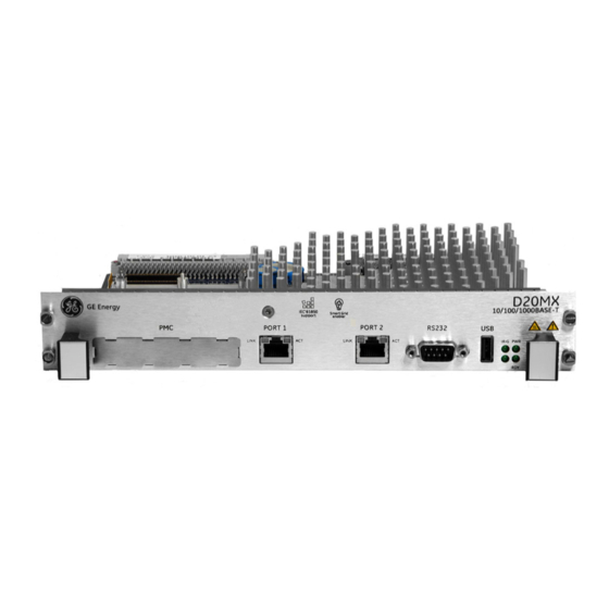
All physical connections are made to the connectors on the rear backplane of the D20 chassis or to the front on the D20MX processor module. D20MX front panel connectors The D20MX front panel can have one of the following layouts: • Ethernet connectors (RJ45); see Figure 14. -
Page 42: General Cabling Requirements
Optic Serial Port Status LEDs Status Port 1 Port 2 supported) LEDs Figure 16: D20MX front panel and fiber optic card with rear access fiber optic connectors Fiber Optic card, D20 chassis back view Fiber Optic Port 1 Fiber Optic... -
Page 43: Link
(TXD, RXD, RTS#, CTS#, DCD#) DTE serial ports, compliant to ANSI/TIA-232 and TIA/EIA-694 specifications and are hosted by UARTs. The D20MX is tested with all 7 serial ports running at 19200 baud with 20% CPU utilization. Refer to application configuration guides for supported baud rates and for data bits. -
Page 44: Twisted-Pair Ethernet (For 526-3001 Only)
Plug network cables into the D20MX twisted-pair Ethernet ports. to network devices If the D20MX is deployed in the presence of strong RF energy in the 110 MHz - 125 MHz band, such as airport ILS localizers or aviation radio transmitters, it is recommended that shielded twisted-pair Ethernet cables be used. -
Page 45: Fiber Optic Ethernet (For 526-3003 And 526-3005Lf Only)
Fiber optic Ethernet (for 526-3003 and 526-3005LF only) The 100BASE-FX variant of the D20MX (GE part numbers 526-3003 and 526-3005) can connect to one or two networks through two fiber-optic Ethernet connections. The data rate on each port is 100 Mbps. -
Page 46: Lan Redundancy
When the primary port (that is, port 1) receives no signal, or detects a fault signal from the remote link partner, the D20MX switches to the secondary port (that is, port 2) if it has a valid link. The D20MX reverts to the primary port if the primary link is restored or no signal is present on the secondary port. - Page 47 D20 Host Name with a two character suffix that matches the derived IP address you wish to override or disable. The suffix conventions are shown in Table 19. The D20 Host Name appears in the D20 Device Wizard as shown in Figure 18. D20MX HARDWARE USER’S MANUAL GE INFORMATION...
- Page 48 CCU B, LAN B FAC_DEFBB The D20MX can be in one of five modes as defined in Table 20. You can find the current mode of the D20MX by navigating to the SHELL in WESMAINT II+ and typing the command...
-
Page 49: Rs-232
WESMAINT II+ facility. SGConfig's Terminal Emulator is an example of a suitable terminal emulation program. The RS-232 port is connected to the D20MX front panel and is also routed to the rear panel as (COM0). The default baud rate is 19,200. - Page 50 Figure 20: Redundant D20 system - If CCU A fails To Field Equipment RS-232 Switch Panel CCU A Serial CCU B Serial Communications Communications RS-232 Switch Monitor and Control CCU A CCU B (F ailed) (Active) Inter-CCU Communications GE INFORMATION D20MX HARDWARE USER’S MANUAL...
-
Page 51: Failover Sequence
Pins 4 on switch panel connectors J2 through J9 are tied together and to the panel’s power supply. Any loading from field devices on these pins will load the RS-232 panel power supply and should be taken into consideration when sizing power supplies. D20MX HARDWARE USER’S MANUAL GE INFORMATION... -
Page 52: Rs-232 Switch Panel Operation
The CCU A/CCU B LED indicator indicates which unit has been activated. Redundancy wiring diagrams Figure 22 illustrates how to wire the D20MX units and RS-232 switch panels to enable system redundancy: The D20MX watchdog (control) port, heartbeat (ping) port, and serial port assignments are software configurable. -
Page 53: D20Mx Hardware User's Manual Ge Information
CHAPTER 3: CONNECTING TO DEVICES AND NETWORKS Figure 22: Redundancy wiring - single RS-232 switch panel D20MX HARDWARE USER’S MANUAL GE INFORMATION... - Page 54 CHAPTER 3: CONNECTING TO DEVICES AND NETWORKS GE INFORMATION D20MX HARDWARE USER’S MANUAL...
-
Page 55: Powering-Up And Testing
Before any of the tests and procedures in this section can be performed, a valid configuration file must be loaded into the D20MX NVRAM. If you have replaced the main board of the D20MX, then you will need to restore the configuration file so that diagnostic tests can be performed. -
Page 56: Terminal Emulation
“Set up a PC to act as a WESMAINTII+ terminal”. See page 57. “Power up the D20MX” on page 57. See page 57. Result: The D20MX automatically runs the Online Start-up test. See “Automatic on-line start-up test” on page 57. -
Page 57: Set Up A Pc To Act As A Wesmaintii+ Terminal
CPU Core Speed The NVRAM CRC test verifies that the configuration header is valid. If this fails, then the D20MX starts with a minimal set of applications that allow the system to be restored. D20MX HARDWARE USER’S MANUAL GE INFORMATION... -
Page 58: Code And Configuration Files
CCU A is Active. Both the PWR A and PWR B LEDs should be illuminated. Connect a NULL modem cable (GE Energy part number 977-0529) to the RS-232 connector on the front panel of the active D20MX. Attach the other end of the cable to the serial communications port of the PC or terminal. -
Page 59: Check That Fail-Over Is Functioning Correctly
CCU A is Active. Both the PWR A and PWR B LEDs should be illuminated. To simulate hardware failure, switch off the Active D20MX at the main power switch on the front of the unit. Result: If the RS-232 is functioning correctly, then it will switch over to the Standby unit and the CCU B LED will illuminate and the CCU A LED will go off. -
Page 60: Verify Either Hardware Or Software Switch-Over
To verify either hardware or software switch-over. Connect a NULL modem cable (GE Energy part number 977-0529) to the RS-232 connector on the front panel of the D20MX designated as CCU B, which was originally the Standby unit. Attach the other end of the cable to the serial communications port of the PC or terminal. -
Page 61: Configuring The Software
An introduction to the software components used in the D20MX. • An overview of the software tools you will use. • How to download image files to the Flash memory on your D20MX module on your system using a serial or network connection. • A description of the SGConfig firmware options •... -
Page 62: Remote And Local User Accounts
B014-1NCG WESMAINT II+ for the D20MX Configuration Guide for details on how to configure the D20MX to use RADIUS. When RADIUS is used, your RADIUS server provides a role ID to the D20MX. The role ID defines which commands and displays the user is allowed to access while logged in to the D20MX. -
Page 63: Download Image Files To The D20Mx
• A NULL modem cable (GE Energy part number 977-0529) connecting the RS-232 connector on the front panel of the D20MX to the serial communications port of a PC or terminal. Prerequisite for image The following items must be available before an application and operating system image... -
Page 64: Download Software Over A Serial Connection
To set up the Tera Term on a PC: Connect a NULL modem cable (GE Energy part number 977-0529) from the RS-232 connector on the front panel of the D20MX to the serial communications port of the PC or terminal. - Page 65 Press Enter to verify that communication is active. Result: The D20M> prompt appears if the connection is active. 5.2. Type rz and press Enter to put the D20MX into the state where it is ready to receive the downloadable code file 5.3.
-
Page 66: Download Image Files Over A Network Connection
Type el /r to ensure that log is clear. Type boot to restart device. Result: The image file load is completed. The flash memory of the D20MX now has the new application and operating system image file loaded. Configuration File... - Page 67 The unit is rebooted once the transfer finishes. Once the reboot completes, the dialog disappears. The whole operation can take up to 8 minutes. The flash memory of the D20MX now has the new application and operating system image file loaded. D20MX HARDWARE USER’S MANUAL...
-
Page 68: Firmware Integrity
Result: The firmware copy operation begins. Both 'vxworks' and 'appl.out' are copied. This operation takes approximately 3 minutes. DO NOT shut off the power to the D20MX while the copy operation is in progress. If power to the D20MX is disrupted, during the copy operation, the firmware will likely be corrupted. -
Page 69: Reverting Old Firmware
Result: The firmware copy operation begins. Both 'vxworks' and 'appl.out' are copied. This operation takes approximately 3 minutes. DO NOT shut off the power to the D20MX while the copy operation is in progress. If power to the D20MX is disrupted, during the copy operation, the firmware will likely be corrupted. -
Page 70: Transfer D20/D200 Configurations To The D20Mx
D20 configuration to SGConfig. • A NULL modem cable (GE part number 977-0529) connecting the RS-232 connector on the front panel of the D20MX to the serial communications port of the configuration computer. GE INFORMATION D20MX HARDWARE USER’S MANUAL... - Page 71 3.6. Click OK. Open the D20MX Factory Default Configuration SAG0001 or SAG0002: click GE > Recent Projects > select SAG0001-02 or SAG0002-02. Copy the firmware definition from the factory default configuration to the project containing the D20 configuration (if you had opted to upgrade the firmware in ConfigPro, then this step is not necessary): 5.1.
- Page 72 7.6. Browse to a folder and click OK, OK, Cancel and Close. Result: The main page of the project appears. Close the D20MX Factory Default Configuration (i.e. SAG0001 or SAG0002): 8.1. Click GE > Close Project. Result: The Close Project window appears.
- Page 73 12.6. Click the Processor tab > General sub-tab. 12.7. From the Part Number field, click Select. Result: The Select a Processor Card window appears. 12.8. Select one of the three D20MX processor type part numbers (526-3001, 526- 3003 or 526-3005). 12.9. Click OK, Firmware tab, and Select.
- Page 74 Result: A warning dialog appears. 14.5. Click Yes. Result: The warning dialog and the Application list popup disappear. 15. Import the RADIUS roles from the D20MX default configuration into the D20 device: 15.1. Double-click the D20 device. Result: The Application List popup appears.
- Page 75 18.1. Click the Project tab of the original D20 device configuration. 18.2. Double-click the D20 device. Result: The Application List popup appears. 18.3. Double-click the WESMAINT II+ application. Result: The WESMAINT II+ table icon set appears. D20MX HARDWARE USER’S MANUAL GE INFORMATION...
- Page 76 21.7. Physically connect the PC's serial port using the RS232 NULL modem cable to either the front serial port of the: – Standby D20MX, if the D20MX is configured for device redundancy, or – Standalone D20MX, if the D20MX is configured for standalone operation.
-
Page 77: Transferring A D200 Configuration To The D20Mx
D20 in the instructions below. Single and multi-processor D200 devices must first be changed into D20 devices before the D20MX processor card option can be selected. To change a D200 device into a D20 device perform the following steps: Start SGConfig. -
Page 78: Configpro
Use this information to update the firmware definition of an existing D20 and D200 device configuration to the D20MX firmware definition. The result is a device archive that you can migrate into SGConfig for the purpose of transferring the D20/D200 configuration to the D20MX. - Page 79 17. Change the Project Name if desired and click OK. Result: The main window of ConfigPro appears with the tree view of the project directory on the left. The new D20MX factory default project appears in the tree view. 18. Double-click on the D20MX factory default project.
- Page 80 FAC_DEF device appear. 23. Close the device configuration by clicking on the door icon. Result: The Main Page of the D20MX factory default project appears with the FAC_DEF device appearing on the page. 24. Click from the menu bar, Device > Firmware.
- Page 81 Result: The main window of ConfigPro appears with the tree view of the project directory on the left. Make a backup copy of the project you want to transfer to the D20MX. 2.1. Select from the menu, Project > Copy Project.
-
Page 82: Software (Feature) Licensing
Right-click on the D20 device you want to transfer and select Tools > Change. Result: The Change Device window appears. Select type D20 and click OK. Follow the steps in section: “Updating a D20 configuration to use the D20MX firmware definition with ConfigPro” on page 78. Software (feature) licensing Version 1.2 of the D20MX introduces the Software (or Feature) licensing capabilities. - Page 83 The file must be named license.key. Use the D20M Shell command CL (Copy License) to process the license file. This command copies the license file to the correct location on the D20MX, and if there are no errors, the D20MX automatically restarts.
- Page 84 If Customer Service sends a batch file (batch.lic), use a SCP (Secure Copy) application, such as WinSCP, to copy the batch file over the network to the /ram directory on the D20MX. Alternatively, use the D20M Shell RZ command to download the license file via Z-Modem through the console port.
-
Page 85: Using The D20Mx
• Fiber optic status port LEDs Front panel LEDs Once the D20MX is powered up, the LED indicators on the front panel become active. The indicators provide status information on the operation of the D20MX. Operational status LEDs The status LEDs indicate the unit’s operational status:... -
Page 86: Lan Port Status Leds
Normally off; reserved for future expansion. IRIG IRIG LAN port status LEDs The LAN Port Status LEDs provide a visual indication of the status for the Ethernet communication ports on the front of the D20MX. LED Display Label Color Status Description LINK Orange for 1000BASE-T. -
Page 87: Servicing The D20Mx
Connectors and cables are intact and firmly attached Removing the D20MX processor module The D20MX can be removed from a non-VME (GE part number 500-0305) or VME (GE part number 500-0280) D20 chassis. Ensure that you are sufficiently grounded to prevent ESD damage to the D20MX or other components. - Page 88 6.5. Store the D20MX fiber card in static-protective packaging. Grasp the D20MX by the front handles and slide the processor module all the way out of the D20 chassis. Allow the D20MX to cool before removing. The heatsink of the D20MX may be extremely hot during and immediately after operation.
-
Page 89: Default Role- Based Access Control Model
Default Role-Based Access Control Model Configured roles in the D20MX When you configure the D20MX to use RADIUS, the D20MX must be configured with a set of roles in the B014 RADIUS Roles Table (B014RADR) of the WESMAINT II+ application (Refer to the B014-1NCG WESMAINT II+ for the D20MX Configuration Guide for more information). - Page 90 Table 25: Modify access flags for WESMAINT (Application number: 14) Description Administrator Engineer Operator Observer Position Time and Date display Peripheral Status display Peripheral Status Detail display COS Buffer display SHELL Digital Inputs display Digital Inputs Detail display Digital Outputs display GE INFORMATION D20MX HARDWARE USER’S MANUAL...
- Page 91 Analog Outputs display Analog Outputs Detail display Transition Counter display Transition Counter Detailed display SOE Buffer display USER LOG display Database Synch display Switch-over display System Status display Communication Status display Complex Object display D20MX HARDWARE USER’S MANUAL GE INFORMATION...
- Page 92 2 - 31 Not Used Table 31: Modify access flags for DNP DPA configuration display (Application number: 32021) Description Administrator Engineer Operator Observer Position 0-23 Not Used Modify Points / Detail Displays 25-31 Not Used GE INFORMATION D20MX HARDWARE USER’S MANUAL...
- Page 93 Description Administrator Engineer Operator Observer Position 0-31 Not Used Table 38: Read access flags for Modbus DCA display (Application number: 59) Description Administrator Engineer Operator Observer Position Any Page 2 - 31 Not Used D20MX HARDWARE USER’S MANUAL GE INFORMATION...
- Page 94 Gateway access to serial port 3 - 31 Not Used Table 46: Modify access flags for IEC 60870-5-101/104 DPA (Application number: 101) Description Administrator Engineer Operato Observer Position r [3] Not Used 1 - 31 Not Used GE INFORMATION D20MX HARDWARE USER’S MANUAL...
- Page 95 Force Digital Output (Digital Output Display) Not Used Not Used Force Analog Output (Analog Output Display) Force R/L Output (R/L Outputs Display) Yes Delete All COS (COS Display) Delete All SOE (SOE Display) 10 - 31 Not Used D20MX HARDWARE USER’S MANUAL GE INFORMATION...
- Page 96 1 - 31 Not Used Table 53: Read access flags for IEC 60870-5 FT1.2 Balanced Data Link (Application num- ber: 32085) Description Administrator Engineer Operato Observer Position r [3] Any Page 1 - 31 Not Used GE INFORMATION D20MX HARDWARE USER’S MANUAL...
-
Page 97: Standards & Compliance Standards
D20MX Processor Appendix B: Standards & Protection Standards & Protection This Appendix lists the standards with which the D20MX has been tested for compliance. Compliance standards Compliance standards are listed for the following categories: • Emission standards; see Table 54 •... - Page 98 Pulse shape: Half sine Pulse duration: 16 mS Acceleration level: 10 g's 1000 pulses per polarity per axis for a total of 6000 pulses IEC 60068-2-30 Damp heat, cyclic (12 h + 12 h cycle) GE INFORMATION D20MX HARDWARE USER’S MANUAL...
- Page 99 For a total of 12 drops IEC 60068-2-78 Humidity Testing 96 hours steady state humidity at 40 °C and 93% RH 1 To comply, the ferrite clamp (460-0073) supplied must be installed on the power cable. D20MX HARDWARE USER’S MANUAL GE INFORMATION...
- Page 100 APPENDIX B: STANDARDS & PROTECTION GE INFORMATION D20MX HARDWARE USER’S MANUAL...
-
Page 101: Frequently Asked Questions
Subsequently, there is no need for additional memory expansion modules. – The firmware flash memory size in the D20MX is 128 MB, compared to the 2 MB of its predecessor. – The D20MX uses a Super Capacitor which allows the system clock to be saved for 14-days even after power off. - Page 102 – -P010 v3.0x6, 3.05, 3.01 and 3.00: PCOMMON for D20A, D20S and D20K – -P087 v1.04, 1.03 and 1.02: pBOOT for D20AC Also see the PCOMMON versions compatible with the D20MX in Table 9 on page 23. What is the recommended operating temperature range of the D20MX? The operating temperature range is 0°C to +70°C.
-
Page 103: Using Configpro With D20Mx
Refer to the “Application definition files and default configurations” on page 128 to see how application definition files and factory default configuration files can be installed. Using ConfigPro to configure and transfer a D20 configuration to a D20MX is done by: •... -
Page 104: Transferring D20 Configurations To The D20Mx
Create a D20MX device. 1.1. Right-click the D20 device. Copy…. 1.2. Select Result: The Select Project and Page to Copy Device to window appears. 1.3. In the Device Name field, rename the device as a D20MX device. GE INFORMATION D20MX HARDWARE USER’S MANUAL... - Page 105 Click the Door icon to close the Application List report. Result: The project containing the created D20MX device reappears. Edit the device properties of the created D20MX device so that it uses an appropriate D20MX SAN firmware file and it has similar device properties to the desired D20MX factory default configuration.
- Page 106 D20MX device to the same project location as the renamed D20 [D20MX device] in step 1.3, this will eliminate the need to copy the SAN firmware to make it available in the firmware library - as described in step 3.3.
- Page 107 APPENDIX D: USING CONFIGPRO WITH D20MX Note: Step 3.3 applies because the D20MX factory default configuration was restored to a different project location - C: drive, as shown above. If this is not the case, right-click on an empty space within the project's main page and click...
- Page 108 APPENDIX D: USING CONFIGPRO WITH D20MX As shown above, the device properties of the factory default configuration 10730-02 uses SAN0001. 3.3.4. Right-click on the factory default configuration's main page and select Firmware. 3.3.5. Select the required SAN firmware and click Copy to transfer this firmware to the project location in step 1.
- Page 109 APPENDIX D: USING CONFIGPRO WITH D20MX This is the location of the copy of the D20 device being modified. In step 1, this D20 device was copied and renamed as a D20MX device. Result: The D20MX device location now has a firmware library that contains the SAN firmware transferred from the previous step.
- Page 110 3.4.3. Confirm the SAN0001/SAN0002 firmware is now associated to the D20MX device (from step 1). 3.5. Manually set the D20MX processor card. Note: In the same device properties, the General tab does not include a D20MX processor card. GE INFORMATION D20MX HARDWARE USER’S MANUAL...
- Page 111 RAM Size 40000000 [HEX] 3.5.2. Manually set the memory model in the D20MX device being modified by selecting the Processor tab > Memory Model tab > Set Manually option. Step 3.6 is applicable if the device configuration were a “LAN-based Device”...
- Page 112 These are both TCP connections. Click OK when the D20MX device properties are set. Result: The applications present in the SAN firmware are applied to this new D20MX device. Carefully configure the applications of interest before generating the tables for the D20MX device.
- Page 113 5.3.2. Double-click on this factory default configuration and click the System Point Database Applications tab. 5.3.3. Double-click on the Wesmaint II+ application. 5.3.4. Import the RADIUS roles from the D20MX default configuration into the D20MX device being modified. While in the D20MX factory default configuration's Wesmaint II+ application, right-click on the RADIUS Role Table [B014RADR].
- Page 114 APPENDIX D: USING CONFIGPRO WITH D20MX 5.3.5. While in the D20MX device created in step 1, double-click and go to the System Point Database tab which contains the Wesmaint II+ application. Right-click on the RADIUS Role Table [B014RADR] and import the B014RADR settings previously exported.
- Page 115 APPENDIX D: USING CONFIGPRO WITH D20MX 5.4.2. Double-click this factory default D20MX configuration and go to the System Point Database Applications tab. 5.4.3. Double-click the System Point Database Applications Table. Select the IP Redundancy Monitor from the list of application and click Descriptors.
- Page 116 APPENDIX D: USING CONFIGPRO WITH D20MX 5.4.6. Go to the D20MX device being modified. Double-click the device. Navigate to the System point database Applications tab. Double-click the System Point Database application. Select the IP Redundancy Monitor from the list of applications. Click Descriptors. Click the Import icon.
- Page 117 APPENDIX D: USING CONFIGPRO WITH D20MX 5.4.8. Confirm the pseudo point descriptions changed as shown below. Click OK to accept the change and to close each window. 5.4.9. Carefully configure all other enabled applications based on their respective configuration guides. This is required before a configuration can be successfully generated without errors.
-
Page 118: Configuration File In Project Directory
The transfer of a D20 configuration into a D20MX configuration is complete. Configuration file in project directory In step 5.4.10, a D20MXDEVICE.SHX file was created after generating the tables of this D20MX device created. This file can be found within the device directory in windows explorer. GE INFORMATION... -
Page 119: Downloading A D20Mx Configuration
Serial configuration download to the D20MX is done from within ConfigPro similar to a ConfigPro terminal D20. emulator and the F7 To use a serial connection to download a configuration to the D20MX, using the ConfigPro terminal emulator and F7 key: Connect a cable; either a: –... - Page 120 APPENDIX D: USING CONFIGPRO WITH D20MX – Wesmaint cable [977-0300] could be used to connect the Wesmaint port at the back of the D20MX chassis to the serial communication port of the PC. Set up the terminal emulator with the D20MX communications parameters. 2.1.
- Page 121 2.5.5. Change the baud rate to match 115200 by selecting the Software Transmit and Software Receive options and then clicking OK. 2.5.6. Reconnect to and login to the D20MX. See step 2.3 [Connect to the D20MX device]. 2.5.7. Download [sync] the configuration from ConfigPro to the D20MX by pressing the F7 key.
- Page 122 APPENDIX D: USING CONFIGPRO WITH D20MX Booting the D20MX resets it to 19200. If the baud rate in the D20MX is not the same as that in the communication properties, the command prompt shows the following characters. If this is the case, change the ConfigPro communication properties to match the 19200 baud of the D20MX.
- Page 123 APPENDIX D: USING CONFIGPRO WITH D20MX Login to the D20MX device. The factory default configuration for the D20MX comes with one default user account with: Username: admin; Password: changeme. Navigate to the D20M prompt; this is called a SHELL prompt - an equivalent of the 68K monitor prompt.
- Page 124 Locate the D20MXDEVICE.SHX file. 8.1. Open Windows explorer. 8.2. Navigate to the project directory where this D20MX device is located. Note: The file name D20MXDEVICE represents the device name. Drag and drop the D20MXDEVICE.SHX file onto the Tera term window. GE INFORMATION...
-
Page 125: Remote [Secure] Transfer Of Configuration
Refer to the B014-1NCG WESMAINT II+ for the D20MX - Configuration Guide for details on how to modify user accounts and how to change the password of a user. The D20MX configuration can be defaulted by pressing CTRL-F on a terminal connected over the front RS232 port during startup. - Page 126 APPENDIX D: USING CONFIGPRO WITH D20MX Login to WinSCP using the D20MX IP address and port number 22. In the D20MX configuration, port 22 has been created in the Services section of the Device LAN Properties. If the following window appears, click Yes.
- Page 127 APPENDIX D: USING CONFIGPRO WITH D20MX Login to the D20M prompt of the D20MX RTU - this is the SHELL [option 3] menu. 10. Suspend the processor by typing sp and pressing Enter. 11. Copy the configuration by typing cc and pressing Enter.
-
Page 128: Application Definition Files And Default Configurations
APPENDIX D: USING CONFIGPRO WITH D20MX Application definition files and default configurations The D20MX Documentation CD contains numerous folders and files. The three main folders for the purpose of this document are highlighted below. In the D20MX Documentation CD contains all of the: •... -
Page 129: Installing Application Definitions: Archived
APPENDIX D: USING CONFIGPRO WITH D20MX Using Windows Explorer, copy/paste the files as shown in the following table. To copy a file, select it and press Ctrl-C. To paste a file, click on the Windows Explorer window showing the new D20MXV1.20 folder and press Ctrl-V. - Page 130 Result: The ConfigPro Application Installer - Select Archive window appears. Select the source directory where the application archive is stored. 3.1. Navigate to the source directory: Go to the D20MX Documentation CD folder > Configuration Files sub-folder > Application Definitions folder. 3.2.
- Page 131 APPENDIX D: USING CONFIGPRO WITH D20MX Click Next. Result: The ConfigPro Application Installer - Installation Complete window appears. Click Finish. D20MX HARDWARE USER’S MANUAL GE INFORMATION...
-
Page 132: Installing Application Definitions: Non-Archived
APPENDIX D: USING CONFIGPRO WITH D20MX Installing application definitions: non-archived In the D20MX Documentation CD, the DEFNs folder contains the APPLDEF sub-folder with all the application definition files. To install missing application definition files: From ConfigPro select Tools > Application Installer. - Page 133 Click Next. Result: The ConfigPro Application Installer - Select Source Directory window appears. Select a Source director [this is the DEFNs/ APPLDEF path within the D20MX Documentation CD]. Select the DAL100.DB file and click Select. The Definitions Found field should indicate Yes.
- Page 134 APPENDIX D: USING CONFIGPRO WITH D20MX Click Next. Result: The ConfigPro Application Installer - Select a ConfigPro Project window appears. Select the ConfigPro project that requires these application definitions. Click Next. Result: The ConfigPro Application Installer - Select Destination Directory window appears.
- Page 135 APPENDIX D: USING CONFIGPRO WITH D20MX Select the destination directory into which the application definitions are to be copied. To determine the destination directory, in ConfigPro, go to File > Preferences > Directories. This is the path highlighted in the screen capture below [C:\WESSYS\ApplDef] 10.
- Page 136 APPENDIX D: USING CONFIGPRO WITH D20MX GE INFORMATION D20MX HARDWARE USER’S MANUAL...
-
Page 137: List Of Acronyms
- an electrical power unit in decibel (dB) Data Collection Application Data Carrier Detect Distributed Network Protocol Data Processing Application Data Transmission Application Data Terminal Equipment Electronic Industries Alliance Electromagnetic Capability D20MX HARDWARE USER’S MANUAL GE INFORMATION... - Page 138 Personal Computer PCBA Printed Circuit Board Assembly PG&E Pacific Gas and Electric Return Merchandise Authorization RoHS Restriction of Hazardous Substances Request To Send Remote Terminal Unit Receive Receive Data SCADA Supervisory Control and Data Acquisition GE INFORMATION D20MX HARDWARE USER’S MANUAL...
- Page 139 UART Universal Asynchronous Receiver-Transmitter Universal Time Coordination Unshielded Twisted Pair Volt Amps, unit of measure V AC Volts, Alternating Current, unit of measure V DC Volts, Direct Current, unit of measure Versa Module Eurocard D20MX HARDWARE USER’S MANUAL GE INFORMATION...
- Page 140 APPENDIX E: LIST OF ACRONYMS GE INFORMATION D20MX HARDWARE USER’S MANUAL...
- Page 141 ..........27 DOWNLOAD COMPLIANCE STANDARDS AND PROTECTION ......97 image files over network ..............66 CONFIGPRO software over serial ................64 download a D20MX configurations .......... 119 when ......................63 transfer D20 configurations ............104 CONFIGURATION FILES ................. 58 CONFIGURATIONS transfer D20/D200 ................70 ELECTRIC SPECIFICATIONS ..............27...
- Page 142 ..................35 RETURN PRODUCT ...................12 REVERT OLD FIRMWARE MANUAL - HOW TO USE ...............69 ................8 RS-232 PORT MATERIALS - REQUIRED ....................49 ................37 MIGRATE D20MX APPLICATION DEFINITIONS TO SGCONFIG MODEMS .......................23 SAFETY PRECAUTIONS ................13 SECURITY .......................16 SERIAL CABLING ..................43 SGCONFIG OPERATIONAL LEDS ................85...
- Page 143 .................. 37 TRANSFER D20/D200 CONFIGURATIONS ........70 TWISTED-PAIR .................... 44 UNPACKING THE D20MX ..............38 UPDATE D20/D200 CONFIGURATIONS ........78 UPGRADE FIRMWARE ................12 UPGRADE KITS ................... 25 USER ACCOUNTS local ......................62 recovery ....................62 D20MX HARDWARE USER’S MANUAL GENERAL...
- Page 144 INDEX GENERAL D20MX HARDWARE USER’S MANUAL...
-
Page 145: Modification Record
Added Migrate D20MX application definitions to SGConfig section. 1.20 July 15, 2013 R. Rees Updated the D20MX application tables, order code table, upgrade kit order code table, procedures in Chapter 5, and Added Appendix D. D20MX HARDWARE USER’S MANUAL GE INFORMATION... - Page 146 GE INFORMATION D20MX HARDWARE USER’S MANUAL...