
Related Manuals for GE TELUM ASLP11


Summary of Contents for GE TELUM ASLP11
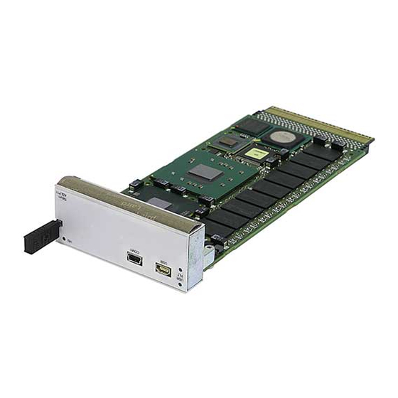
- Page 1 Intelligent Platforms Hardware Reference Manual TELUM ASLP11, ASLE11 Third Edition Publication No. HRMASLP113E...
-
Page 2: Document History
DRAM size 2GBit, 4GBytes Ethernet 82571 from Intel New JTAG Power consumption updated Accept changes from PS; change to GE front & rear page; company name change; cosmetic changes Photos now show ASLP11 Thermal limit diagrams added Correct company name, copyright etc. -
Page 3: Legal Information
Even if this code or software is merged with any other code or software program, it remains subject to the terms and conditions of this license. If you copy, or merge, this code or software, you must reproduce and include all GE Intelligent Platforms copyright notices and any other proprietary rights notices. -
Page 4: Regulatory Compliance
Any operational system with cables for I/O signals, connectivity or peripheral devices provides an entry point for ESD and EMI. If GE Intelligent Platforms does not manufacture the complete system, including enclosure and cables, it is the responsibility of the system integrator and end user to protect their system against potential problems. -
Page 5: Waste Disposal
RTM if a cable is attached and routed outside the enclosure. It has to be done at the physical entry point as specified above. Products manufactured by GE Intelligent Platforms should normally be suitable for use in properly designed and produced customer equipment (system boxes or operational systems) without any major redesign. - Page 6 +49-821-5034-119 Web: www.ge-ip.com E-Mail: sales.augsburg.ip@ge.com GE Intelligent Platforms on the Web: http://www.ge-ip.com For contact and other information (service, warranty, support etc.) see address list in chapter: ‘Support, Service’. GE Intelligent Platforms – ASLP11 Hardware Reference Manual, Third Edition Page 6...
-
Page 7: Welcome
The TELUM ASLP11 AMC Single Board Computer is a fully IBM-AT compatible stand-alone PC equipped with numerous functions and add-on features on a minimized board size. This board is member of the GE Intelligent Platforms TELUM family which includes a variety of different AMC type boards, carriers and systems. -
Page 8: Product Properties
20 °C (68 °F). Because of only marginal variations within a limited range of altitudes these products operate as specified within altitudes from sea level to 1000 m (3300 ft.). GE Intelligent Platforms can assist the user of these components in planning operation outside this altitude range upon request. -
Page 9: Support, Service And Warranty
Support, Service and Warranty The manufacturer grants the original purchaser of GE Intelligent Platforms products a warranty of 24 months from the date of delivery. For details regarding this warranty refer to Terms & Conditions of the initial sale. Please see chapter “Support, Service, and Warranty Information” for further details on repairs and product support. -
Page 11: Table Of Contents
ESD/EMI issues Waste Disposal Corporate addresses WELCOME Product Properties Support, Service and Warranty CONTENTS CHAPTER 1 INTRODUCTION CHAPTER 2 UNPACKING AND INSPECTION Unpacking and Handling Initial Inspection Delivery Volume GE Intelligent Platforms – ASLP11 Hardware Reference Manual, Third Edition Page 11... - Page 12 CHAPTER 5 INTERFACES Front Panel Interfaces ASLP11 Connectors AMC Connector Port Mapping USB Interfaces P1680 Serial Interfaces P1682 CHAPTER 6 RESOURCES Memory Map Register Set Standard Register Set GE Intelligent Platforms – ASLP11 Hardware Reference Manual, Third Edition Page 12...
- Page 13 Hot Swap SMBus devices IPMB (external I²C) Temperature Sensor LM83 Serial EEPROM Geographic Addressing Watchdog LEDs JTAG CHAPTER 8 SPECIFICATIONS Power Consumption No Battery Usage Environmental conditions Electrical Characteristics GE Intelligent Platforms – ASLP11 Hardware Reference Manual, Third Edition Page 13...
- Page 14 Isolation Placement Plan Component Side ASLP11 V0 Placement Plan Solder Side ASLP11 V0 APPENDIX A SUPPORT AND WARRANTY INFORMATION Technical Support Support on the Web Warranty Error Report GE Intelligent Platforms – ASLP11 Hardware Reference Manual, Third Edition Page 14...
-
Page 15: Table Of Figures
............................17 IGURE BOARD 2: B ............................19 IGURE LOCK DIAGRAM 3: P , V0....................58 IGURE LACEMENT PLAN COMPONENT SIDE 4: P , V0 ......................59 IGURE LACEMENT PLAN SOLDER SIDE GE Intelligent Platforms – ASLP11 Hardware Reference Manual, Third Edition Page 15... - Page 16 ABLE NVIRONMENTAL VALUES 16: S ASLP11 .................55 ABLE HOCK AND VIBRATION VALUES FOR THE 17: M ........................55 ABLE AXIMUM HEIGHT USAGE 18: S ........................57 ABLE UPPLY VOLTAGE RANGES GE Intelligent Platforms – ASLP11 Hardware Reference Manual, Third Edition Page 16...
-
Page 17: Introduction
Personal Computer can only offer with several add-on cards. Extension boards can be connected via the AMC interface. The minimized board size and the large number of interfaces and GE Intelligent Platforms – ASLP11 Hardware Reference Manual, Third Edition Page 17... - Page 18 ASLP11 to be used in many applications. See the following block diagram for the board design. GE Intelligent Platforms – ASLP11 Hardware Reference Manual, Third Edition Page 18...
-
Page 19: F Igure 2: B Lock Diagram
Figure 2: Block diagram GE Intelligent Platforms – ASLP11 Hardware Reference Manual, Third Edition Page 19... - Page 20 Works either as PCIe root complex or as PCIe endpoint. On request one USB and one serial port IPMI Hitachi controller for support of Intelligent Peripheral Management Interface. GE Intelligent Platforms – ASLP11 Hardware Reference Manual, Third Edition Page 20...
- Page 21 +3.3 V for IPMI Management controller supply +12 V for board supply Approval Designed to meet standard UL1950, CE class A, FCC-A Styles available ASLP11 is available in standard or extended temperature style. GE Intelligent Platforms – ASLP11 Hardware Reference Manual, Third Edition Page 21...
-
Page 23: Unpacking And Inspection
Extra caution should be taken in cold and dry weather when static easily builds up. GE Intelligent Platforms – ASLP11 Hardware Reference Manual, Third Edition Page 23... -
Page 24: Unpacking And Handling
If evidence of damage or rough handling is found, you should notify the shipping service and GE Intelligent Platforms as soon as possible. -
Page 25: Initial Inspection
If damage is observed (usually in the form of bent component leads or loose socketed components), contact GE Intelligent Platforms for additional instructions. Depending on the severity of the damage, it may need to be returned to the factory for repair. -
Page 27: Advice
See page 23 for details on how to prevent “zapping” the board with ESD. GE Intelligent Platforms – ASLP11 Hardware Reference Manual, Third Edition Page 27... -
Page 28: General Advice
The board is running properly now and is ready to be installed and setup for your application. GE Intelligent Platforms – ASLP11 Hardware Reference Manual, Third Edition Page 28... -
Page 29: Entering The Bios Setup
If the board does not perform as described above, some damage may have occurred in shipping or the board is not installed or set up properly. Contact GE Intelligent Platforms technical support as described in chapter “Support, Service, and Warranty Information”... -
Page 31: Power Supply
LEDs can blink in different frequencies or be on continuously. The blue Hot Swap LED (HS) is required and used according to the AMC.0 specification. GE Intelligent Platforms – ASLP11 Hardware Reference Manual, Third Edition Page 31... -
Page 32: Booting
This version is a rather early one and hopefully some of the long periods will speed up. The times depend mainly on the memory size and they are measured with 1GB and quick boot enabled. All postcodes are shown in hex. GE Intelligent Platforms – ASLP11 Hardware Reference Manual, Third Edition Page 32... -
Page 33: Table 1: Bootup Timing
The necessary software/driver and operating system handling is not done within the BIOS of the ASLP11, because all the tasks to recognize new inserted boards, to re-enumerate the PCI memory space while other cards/transfers are GE Intelligent Platforms – ASLP11 Hardware Reference Manual, Third Edition Page 33... -
Page 34: Unexpected Resets
BIOS. These tasks have to be fully done by the used operating system. Currently GE Intelligent Platforms have no drivers to support these functionalities. The handling of the blue LED is also done within the necessary drivers. So do not expect the blue LED to go on and off according to the AMC specification if no driver is loaded. -
Page 35: Front Panel Interfaces
Front Panel Interfaces Refer to the next drawing for the location of interfaces on the front panel of the ASLP11 board: GE Intelligent Platforms – ASLP11 Hardware Reference Manual, Third Edition Page 35... -
Page 36: Aslp11 Connectors
TCLKC Not connected TCLKD Not connected * violates AMC.0 if optionally mounted, because there is no Tx/Rx separation within the USB. The voltage level is according to AMC.0. GE Intelligent Platforms – ASLP11 Hardware Reference Manual, Third Edition Page 36... -
Page 37: Table 3: Connector J9000 Pin Assignments
Tx3- SATA 1 Transmitter - TCLKC- Not connected Logic Ground Logic Ground Rx3+ SATA 1 Receiver + Tx15+ Not connected Rx3- SATA 1 Receiver - Tx15- Not connected GE Intelligent Platforms – ASLP11 Hardware Reference Manual, Third Edition Page 37... - Page 38 PCI Exp 5 Receiver – Logic Ground Logic Ground FCLKA+ PCI Exp Clock+ Tx8+ PCI Exp 4 Transmitter + FCLKA- PCI Exp Clock- Tx8- PCI Exp 4 Transmitter – GE Intelligent Platforms – ASLP11 Hardware Reference Manual, Third Edition Page 38...
-
Page 39: Table 4: J9000 Additional Functions
One RS232 serial channel is available at the front panel. It is a mini USB-B type connector. For connection of standard female DSUB9 connectors please use the suitable adaptor cable YLU050MD from GE Intelligent Platforms. GE Intelligent Platforms – ASLP11 Hardware Reference Manual, Third Edition... -
Page 40: Table 6: Serial Interface P1682 Pin Assignments
* This pin is not connected within the adapter cable YLU050MD. Therefore only a TxD/RxD handshaked (with CTS) connection is possible. Users needing a full TxD/RxD and RTS/CTS handshake must build there own adapter cable. GE Intelligent Platforms – ASLP11 Hardware Reference Manual, Third Edition Page 40... -
Page 41: Table 7: Memory Map
System BIOS automatically configures (PnP, Plug and Play) each PCI device to avoid address conflicts. Many device drivers show the actual address locations after installation and loading. GE Intelligent Platforms – ASLP11 Hardware Reference Manual, Third Edition Page 41... -
Page 42: Table 8: Standard Register Set
The interrupt routing for standard components such as COM1/2 or LPT1 is in compliance with standard PC/AT systems. Unused interrupts can be used for add-on cards or other board specific PCI devices such as SCSI and Ethernet. GE Intelligent Platforms – ASLP11 Hardware Reference Manual, Third Edition Page 42... -
Page 43: Table 9: Interrupts
For example, interrupt 10 may be given a higher priority than interrupt 3. • More Interrupts. The I/O APIC in the Intel 3100 supports a total of 24 interrupts. GE Intelligent Platforms – ASLP11 Hardware Reference Manual, Third Edition Page 43... - Page 44 For complete operation description please refer to the “Intel 3100 Controller” datasheet. GE Intelligent Platforms – ASLP11 Hardware Reference Manual, Third Edition Page 44...
-
Page 45: Processor
(PCIe). The ASLP11 chipset works as a PCIe root complex (‘Master’) and has an onboard PCIe switch PEX8518 from PLX towards the AMC connect. This PCIe switch gives the possibility to work as an end point device GE Intelligent Platforms – ASLP11 Hardware Reference Manual, Third Edition Page 45... -
Page 46: Interrupt Controller
Counter 1 generates a refresh request signal and Counter 2 generates the sound for the speaker. The following table gives an overview over the 8254 functions. GE Intelligent Platforms – ASLP11 Hardware Reference Manual, Third Edition Page 46... -
Page 47: Table 10: Interval Timer Functions
The ASLP11 has some USB 2.0 channels. These are backward compatible to USB 1.0/1.1. The USB host controller supports legacy Keyboard/Mouse usage with USB–based keyboard and mouse without using additional software drivers. GE Intelligent Platforms – ASLP11 Hardware Reference Manual, Third Edition Page 47... -
Page 48: Table 11: Operating Systems
The drivers available for the Ethernet controller support a large number of operating systems. The table shows operating systems supported by the available software: Table 11: Operating systems Type System NDIS NDIS Windows 2000, XP LINUX GE Intelligent Platforms – ASLP11 Hardware Reference Manual, Third Edition Page 48... -
Page 49: Additional Devices
Devices marked by * are handled by BIOS. It is strongly recommended not to access these devices by user software. An X at bit 0 represents the R/#W bit. GE Intelligent Platforms – ASLP11 Hardware Reference Manual, Third Edition Page 49... -
Page 50: Temperature Sensor Lm83
For more information please see the Intel 3100 Controller datasheet and the ‘Board Specific Hardware Programmer’s Manual’. LEDs Three LEDs are available at the front panel bicolor (’FLT’), green (’in Service’) and blue (HS). GE Intelligent Platforms – ASLP11 Hardware Reference Manual, Third Edition Page 50... -
Page 51: Table 13: Bios Power-Up Status
JTAG The ASLP11 supports the JTAG test interface according to the AMC.0 specification. For more information about the physical connections within the queue please contact GE Intelligent Platforms. GE Intelligent Platforms – ASLP11 Hardware Reference Manual, Third Edition Page 51... - Page 52 GE Intelligent Platforms – ASLP11 Hardware Reference Manual, Third Edition Page 52...
- Page 53 CFM (cubic feet per minute) or m³/h (cubic meter per hour) per ATCA slot. Alternatively you can find the linear air speed shown in m/s (meter per second). GE Intelligent Platforms – ASLP11 Hardware Reference Manual, Third Edition Page 53...
-
Page 54: Table 14: Aslp11 Typical Power Consumption (+12.0 V)
The onboard IPMI controller consumes less than 0.1 A from the 3.3 V management power supply. • Connectors P1680 provide VCC voltage (+5 V). The total current drawn from this source must not exceed 0.5 A. GE Intelligent Platforms – ASLP11 Hardware Reference Manual, Third Edition Page 54... -
Page 55: Table 15: Environmental Values
Spectrum 5 to 100 Hz Acceleration Shock Amplitude 12 g Duration 6 ms Table 17: Maximum height usage C-, I-Style Maximum height Operating 4.5 km Storage 12 km GE Intelligent Platforms – ASLP11 Hardware Reference Manual, Third Edition Page 55... - Page 56 1.5GHz one core TDP 45,0 1.5GHz both cores TDP two 1.5GHz one core TDP 40,0 two 1.5GHz both cores TDP 35,0 30,0 25,0 20,0 air speed within slot GE Intelligent Platforms – ASLP11 Hardware Reference Manual, Third Edition Page 56...
-
Page 57: Table 18: Supply Voltage Ranges
0.8 mm in all PCB layers. However, most standard USB devices will connect FGND with GND directly in the device. Also standard racks (our starter cage too) connect both grounds at the power supply for safety reasons. GE Intelligent Platforms – ASLP11 Hardware Reference Manual, Third Edition Page 57... -
Page 58: Placement Plan Component Side Aslp11 V0
Placement Plan Component Side ASLP11 V0 Figure 3: Placement plan component side, V0 GE Intelligent Platforms – ASLP11 Hardware Reference Manual, Third Edition Page 58... -
Page 59: Placement Plan Solder Side Aslp11 V0
Placement Plan Solder Side ASLP11 V0 Figure 4: Placement plan solder side, V0 GE Intelligent Platforms – ASLP11 Hardware Reference Manual, Third Edition Page 59... -
Page 61: Technical Support
AUS, NZ) Technical Support If you should have a problem with a GE Intelligent Platforms product: Free technical support is available by phone, fax or email. Telephone support is available at main locations or at the regional center where the product was bought. -
Page 62: Support On The Web
• RMA Number, if applicable • Product & Serial Number • Part Number • Version • Contact: Name & Phone Number • Detailed Description of the Problem/Defect GE Intelligent Platforms – ASLP11 Hardware Reference Manual, Third Edition Page 62... -
Page 63: Ge Intelligent Platforms - Aslp11 Hardware Reference Manual, Third Edition
GE Intelligent Platforms – ASLP11 Hardware Reference Manual, Third Edition Page 63... -
Page 64: Additional Resources
© 2010 GE Intelligent Platforms Embedded GE Intelligent Platforms Additional Resources Systems, Inc. All rights reserved. Information Centers * indicates a trademark of GE Intelligent For more information, please visit Platforms, Inc. and/or its affiliates. All other the GE Intelligent Platforms Embedded Systems Americas:...