Table of Contents
Advertisement
Quick Links
WARNING
- POTENTIALFIREAND SHOCKHAZARD
• To reduce therisk o fsevere injury o r death, follow all installation
instructions
• Clothes dryer installation
must be performedby a qualified
installer
• Install
theclothes d ryer according t otheseinstructions
and inaccordance withlocal c odes
• This dryermust be exhausted totheoutdoors
• Use only4' rigid m etalducting f orexhausting t heclothes d ryer to theoutdoors
• DO NOT install
a clothes d ryer withflexible
plastic ducting materials If flexible
metal(semirigid orfoil t ype) ductisinstalled,
it must be UL-listed
and installed
inaccordance withtheinstructions
foundin'Connecting theDryer to House Vent'on page
7 ofthis manual Flexible
ducting materials a reknown tocollapse,
be easily c rushed, a nd traplint Theseconditions will
obstruct drger airflow and increase the risk of fire.
• Do not install or store this appliance in ang location where it could be exposed to water andlor weather.
• Save these instructions. (Installers:Be sure to leave these instructions with the customer.)
• This appliance must be properlg grounded and installed as described in these instructions.
IMPORTANT
• Exhousting the dryer to the outside
is required to prevent large
amounts of moisture, lint and other
products of combustion from being
blown into the room.
• Service information and a wiring
diagram are located in the dryer
access panel.
TOOLS NEEDED
Slip-joint pliers
Phillips-head and flat-blade screwdrivers
Ratchet with 3/8" socket
Carpenter's level
Adjustable wrenches
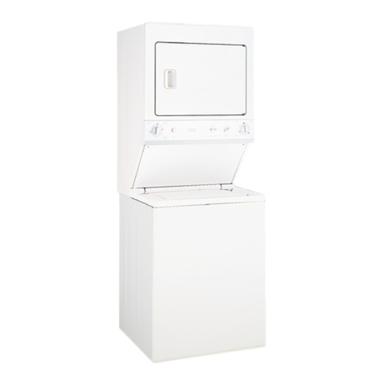
PRODUCT DIMENSIONS
@
®
®
_19_/8
'' ]
Vent _/_
/
\+/
/
Water ....... _:;
inlets (rear)
_S Drainoutlet
(rear)
_27"
2 C /16"
41V4"
36VS
,,,"
_o_',,,
,,
,,,
'
]
b
_30_Y_8
''
21/2
,,
117/18"
149-90383
I
05-09 JR
Advertisement
Table of Contents

Related Manuals for GE 49-90383


Summary of Contents for GE 49-90383
- Page 1 WARNING - POTENTIALFIREAND SHOCKHAZARD • To reduce therisk o fsevere injury o r death, follow all installation instructions • Clothes dryer installation must be performedby a qualified installer • Install theclothes d ryer according t otheseinstructions and inaccordance withlocal c odes •...
-
Page 2: Power Cord Connection
Installation Instructions UNPACKING SPACEMAKER'" UNPACKING SPACEMAKER'" (CONT.) from NOTE: T he tub blocking pod, shipping bolt and plastic I-I-I Remove tope two corner pods rear spacer should be retained for use if the appliance bottom corners ofappliance. is transported at o later dote. thefour r2-1 using shipping corner posts, l og... - Page 3 Installation Instructions CONNECTING TO PLUMBING FACILITIES MOVING SPACEMAKER'" TO OPERATING LOCATION (CONT.} Turn the water on and check for leaks at both connections. Remove the 2 screws securing the access panel to the dryer cabinet. Lift the front access panel until the tabs can be disengaged from the dryer Place formed end of drain hose in drain facility cabinet and remove the panel.
-
Page 4: Plumbing Information
Installation Instructions APPLIANCE OPERATIONAL CHECKOUT DRAIN REQUIREMENTS IT71 Make sure all packing and shipping materials • DRAIN RATE- The drain or standpipe must be capable are removed, including the washer shipping bolt of accepting a discharge at the rate of 16 gallons per minute. -
Page 5: Wire Connection
Installation Instructions CONNECTING APPLIANCE USING 3-WIRE CONNECTION (UNGROUNDED 3-WIRE CONNECTION NEUTRAL) This appliance is manufactured with the neutral Remove the terminal block cover located at the connected to the frame. If local codes do not )ermit rear of the dryer. neutral grounding, proceed as follows: Instoll o UL-recognized stroin relief in the one-inch Remove the terminol block occess cover. -
Page 6: Exhaust Information
Installation Instructions CONNECTING APPLIANCE USING CONNECTING APPLIANCE USING 4-WIRE CONNECTION 4-WIRE CONNECTION (CONT.) A CAUTION: Be sure electricity is OFFat power source (circuit breaker/fuse box). F8-1 Plug power cord into electrical outlet. Return to Step 15 on page 3. NOTE:TH ISAPPLIANCEISNOTAPPROVEDFOR120-VOLT OPERATION. - Page 7 Installation Instructions EXHAUST INFORMATION (CONT.) CONNECTING THE DRYER TO HOUSE VENT (CONT.} EXHAUST DUCT LENGTH INFORMATION UL-Listed Flexible Metal (Foil-Type)Transition Duct • The MAXIMUMALLOWABLElength of the exhaust system • In special installations, it may be necessary to connect depends upon the type of duct, number of turns, the the dryer to the house vent using a flexible metal type of exhaust hood (wall cap) and all conditions noted (foil-type) duct.
- Page 8 Installation Instructions MOBILE HOME INSTALLATION DOOR VENTILATION OPENING • Installation must conform to Manufactured Home A minimum of 120 square inches of opening, equally Construction and Safety Standard, Title 24 CFR, divided at top and bottom, is required. Air openings are Part 32-80.