
Related Manuals for Grizzly G0708


Summary of Contents for Grizzly G0708
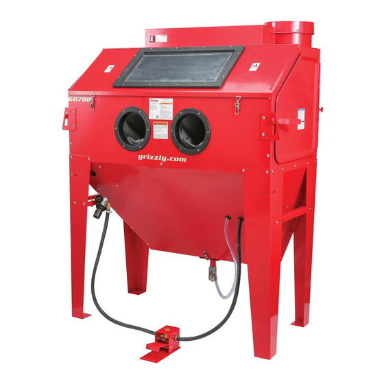
- Page 1 MODEL G0708 24" x 48" BLAST CABINET OWNER'S MANUAL WARNING: NO PORTION OF THIS MANUAL MAY BE REPRODUCED IN ANY SHAPE OR FORM WITHOUT THE WRITTEN APPROVAL OF GRIZZLY INDUSTRIAL, INC.
- Page 2 This manual provides critical safety instructions on the proper setup, operation, maintenance, and service of this machine/tool. Save this document, refer to it often, and use it to instruct other operators. Failure to read, understand and follow the instructions in this manual may result in fire or serious personal injury—including amputation, electrocution, or death.
-
Page 3: Table Of Contents
Table of Contents INTRODUCTION ..........................2 SECTION 1: SAFETY ........................6 SECTION 2: CIRCUIT REQUIREMENTS ..................9 SECTION 3: Setup ......................... 10 SECTION 4: OPERATIONS ......................21 SECTION 5: ACCESSORIES ......................29 SECTION 6: MAINTENANCE......................30 SECTION 7: SERVICE ........................31 SECTION 8: WIRING ........................ -
Page 4: Introduction
INTRODUCTION Manual Accuracy Contact Info your machine may not exactly match the manual Machine Description www.grizzly.com... - Page 5 Identification...
-
Page 6: Machine Data Sheet
Machine Data Sheet MACHINE DATA SHEET MODEL G0708 24" X 48" BLAST CABINET Product Dimensions: Shipping Dimensions: Electrical: Dust Collector Motor: Operation Information:... - Page 7 General Specifications: Other Specifications: Features:...
-
Page 8: Section 1: Safety
SECTION 1: SAFETY For Your Own Safety, Read Instruction Manual Before Operating this Machine The purpose of safety symbols is to attract your attention to possible hazardous conditions. This manual uses a series of symbols and signal words intended to convey the level of importance of the safety messages. -
Page 9: Safety Instructions For Machinery
Safety Instructions for Machinery DISCONNECTING POWER SUPPLY. APPROVED OPERATION. INTENDED USE. CHILDREN & BYSTANDERS. STABLE MACHINE. FEED DIRECTION. SECURING WORKPIECE. FORCING MACHINERY. UNATTENDED OPERATION. GUARDS & COVERS. MAINTENANCE & INSPECTION. REMOVING TOOLS. AWKWARD POSITIONS. EXPERIENCING DIFFICULTIES. DANGEROUS ENVIRONMENTS. - Page 10 Additional Safety for Blast Cabinets 5. WORK AREA SAFETY. PERSONAL PROTECTION EQUIPMENT. 6. MAINTAINING COMPONENTS. SAFE MEDIA BLASTING. 8. CORRECT LIGHTING. 2. LEAVING THE AREA. 9. LOADING & UNLOADING. 3. MAINTAINING MACHINE. 10. SAFE MAINTENANCE. 4. SAFE ENVIRONMENT. 11. SAFE MEDIA BLASTING. No list of safety guidelines can be complete.
-
Page 11: Section 2: Circuit Requirements
SECTION 2: CIRCUIT REQUIREMENTS Power Connection Device 110V Operation Figure Serious personal injury could occur if you GROUNDED 5-15 RECEPTACLE connect the machine to power before com- pleting the setup process. DO NOT connect the machine to the power until instructed later in this manual. -
Page 12: Section 3: Setup
SECTION 3: SETUP Needed for Setup This machine presents serious injury hazards to untrained users. Read through this entire manu- al to become familiar with Description the controls and opera- tions before starting the machine! Wear safety goggles dur- ing the entire setup pro- cess! Unpacking This machine and its com-... - Page 13 Inventory Note: If you can't find an item on this list, check the mounting location on the machine or examine the packaging materials carefully. Occasionally we pre-install certain components for shipping purposes. Box 1: (Figure 3) Figure 2. SUFFOCATION HAZARD! Immediately discard all plas- tic bags and packing materi- als to eliminate choking/suf-...
- Page 14 Hardware Recognition Chart...
-
Page 15: Site Considerations
Site Considerations Weight Load Physical Environment Machine Data Sheet Space Allocation Electrical Installation See below for required space allocation. Lighting Children or untrained people may be seriously injured by this machine. Only install in an access restricted location. Figure 3. -
Page 16: Mounting To Shop Floor
Using Machine Mounts Mounting to Shop Figure 5 Floor Bolting to Concrete Floors Figure 4 Figure 5 NOTICE We strongly recommend securing your machine to the floor if it is hardwired to the power source. Consult with your electrician to ensure compliance with local codes. Figure 4 NOTICE Anchor studs are stronger and more per-... - Page 17 Air Supply Setup System Diagram Page 39...
- Page 18 Assembly To assemble the blast cabinet: Figure 6 Figure 7. Figure 8 Figure 6. Figure 6 Figure 8. Figure 9 Figure 7 Figure 9.
- Page 19 Figure 11 Figure 10 Figure 11. Figure 12 Figure 10. Figure 12. Figure 10 Figure 10...
- Page 20 Figure 13 Figure 15 Figure 15. Figure 13. Figure 16 Figure Figure 14. Figure 16.
-
Page 21: Test Run
Test Run Troubleshooting Page 30 Before starting the machine, make sure you have performed the preceding assembly and adjustment instructions, and you have read through the rest of the manual and are familiar with the various functions and safety features on this machine. Failure to follow this warning could result in serious personal injury or even death! To test run the machine:... - Page 22 Note: If after this test, the regulator gauge needle drops more than a few PSI when you press the foot pedal, verify that the air supply is not restricted. If setup correctly, the blast gun media suction tube should draw 15-17 inches of mercury on a manometer.
-
Page 23: Section 4: Operations
WE STRONGLY RECOMMEND that you read books, trade magazines, or get formal training before beginning any projects. Regardless of the content in this section, Grizzly Industrial will not be held liable for accidents caused by lack of train- ing. -
Page 24: Basic Operation
Basic Operation Figure 19 Page To use the blast cabinet: Maintenance Page 29 Pre- Use Overview Page 20 PUT ON safety goggles and a respirator. Figure 19. Page 25 Note: It is very important to maintain concentricity of the tip orifice as it wears. To Note: Loading just enough media for the job at do this you must rotate the media blasting tip hand will help you prevent over-using or having... - Page 25 Figure 23 Figure 21 Typically this is a trial-and-error process, but a good range to start at is between 60 and 80 PSI. Troubleshooting Page Figure 23. Figure 24 Figure 21. Figure 22 Figure 24. Figure 22.
- Page 26 Figure 25 Note: If the gun or metering valve begins to clog or becomes completely clogged during use, cover the hole in the blast tip tightly, and pull the gun trigger. Air pressure will be then diverted back through the media suction piping and usually blow out the clog.
- Page 27 Blasting Media Grizzly Blasting Media Part Numbers G6535: Media Cost vs. Productivity G6536: G6537: G6538: Aluminum Oxide (8.5-9) Silicon Carbide (9-9.5) Maximizing Media Life Sand Type Media (6-7)
- Page 28 Steel Type Media —Crushed Glass (5.5) —Steel Grit (8-9) —Garnet (6.5-7.5): —Steel Shot (6-7.5) Slag Media —Copper Slag (7-8): Glass and Garnet Type Media —Glass Beads (5.5): —Coal Slag (6-7):...
- Page 29 Plastic Beads —Pumice (6-7): —Ground Corn Cob (4.5): —Urea (3-4): —Melamine (3-4): —Sodium Bicarbonate (2.4): —Acrylic (3-4): Soft Blast Media —Ground Walnut: (4.5-5)
- Page 30 Media Notes...
-
Page 31: Section 5: Accessories
SECTION 5: ACCESSORIES H7359—Campbell Hausfeld: 5 HP, 60-gallon H2499—Small Half-Mask Respirator Air Compressor H3631—Medium Half-Mask Respirator H3632—Large Half-Mask Respirator H3635—Cartridge Filter Pair P100 H3719—Porter Cable: 7 ⁄ HP, 80-gallon 2-stage Cast-iron Air Compressor Figure 28. G2815— Campbell Hausfeld: 7 ⁄ 80-gallon 2-stage Compressor Basic Eye Protection T20501—Face Shield Crown Protector 4"... -
Page 32: Section 6: Maintenance
SECTION 6: MAINTENANCE Cleaning Schedule GROUND 5-15 RECEP Always disconnect power Wear safety goggles and a respirator when and the air supply to the cleaning the cabinet or the filter. Failure to machine before perform- comply can cause serious personal injury. 5-15 PLUG ing maintenance. -
Page 33: Section 7: Service
SECTION 7: SERVICE Troubleshooting Operation Page 25 Page 22... - Page 34 Motor and Electrical Page Filter Replacement Wear safety goggles and a respirator when cleaning the cabinet or the filter. Failure to comply can cause serious personal injury. Figure 31. To replace the filter: Figure 31 Figure 31...
- Page 35 Motor Brush Figure 33 Replacement Tools Needed Figure 33. To replace the brushes: Figure 34 Figure 32 Figure 34. Figure 32. Figure 32...
- Page 36 Figure 35 Figure 37 Figure 35. Figure 36 Figure 38 Figure 36. Figure Figure 37 Figure 38. Figure 37.
- Page 37 Figure 41 Figure 39 Figure 39. Figure Figure 41. Figure 40.
-
Page 38: Section 8: Wiring
SECTION 8: WIRING Wiring Safety Instructions SHOCK HAZARD. WIRE/COMPONENT DAMAGE. MOTOR WIRING. MODIFICATIONS. CAPACITORS/INVERTERS. WIRE CONNECTIONS. CIRCUIT REQUIREMENTS. EXPERIENCING DIFFICULTIES. The photos and diagrams included in this section are best viewed in color. You can view these pages in color at www.grizzly.com. -
Page 39: Wiring Diagram
Wiring Diagram View this page in color at www.grizzly.com. Worklamp Assembly READ ELECTRICAL SAFETY ON PAGE 35! - Page 40 Air System Diagram WARNING! DISCONNECT POWER AND AIR SUPPLY BEFORE ADJUSTMENTS, MAINTENANCE, OR SERVICE. READ ELECTRICAL SAFETY ON PAGE 35!
- Page 41 Electrical Component Locations Figure 42. Figure 43. Figure 45. Figure 46. Figure 44. READ ELECTRICAL SAFETY ON PAGE 35!
-
Page 42: Section 9: Parts
SECTION 9: PARTS... -
Page 43: Parts List
Parts List REF PART # DESCRIPTION REF PART # DESCRIPTION P0708001 RIGHT DOOR 39-9 P0708039-9 CANISTER PLUNGER W/SPRING P0708002 LEFT DOOR 39-10 P0708039-10 DOOR P0708003 DOOR LEVER P0708040 RUBBER EDGE SEAL P0708004 BLAST GUN ASSEMBLY P0708041 FOOT VALVE P0708004-1 BLAST GUN BODY P0708042 VALVE PLUG P0708004-2... - Page 44 MUST maintain the original location and readability of the labels on the machine. If any label is removed or becomes unreadable, REPLACE that label before using the machine again. Contact Grizzly at (800) 523-4777 or www.grizzly.com to order new labels.
- Page 45 WARRANTY CARD The following information is given on a voluntary basis. It will be used for marketing purposes to help us develop better products and services. Of course, all information is strictly confidential. Note: We never use names more than 3 times. _____________________________________________________________________ _________________________________________________________________________________ _________________________________________________________________________________...
-
Page 47: Warranty And Returns
WARRANTY AND RETURNS... - Page 48 ® Buy Direct and Save with Grizzly – Trusted, Proven and a Great Value! ~Since 1983~ Visit Our Website Today For Current Specials! ORDER 24 HOURS A DAY! 1-800-523-4777...