Advertisement
- 1 Package contents
- 2 Overview
- 3 Step 1. Connect the WAX218
- 4 Step 2. Join the default WiFi network
- 5 Step 3. Log in to the local browser UI
- 6 Other setup methods
- 7 Support and Community
- 8 Regulatory and Legal
- 9 Mounting options
- 10 Mount to a solid wall
- 11 Mount to a T-bar
- 12 Mount to a solid ceiling
- 13 Documents / Resources
Package contents

 Note: Power up your WAX218 by connecting it to a PoE+ switch. As an option, you can order a 12V, 2.5A power adapter. For more information about the power adapter, see netgear.com/support .
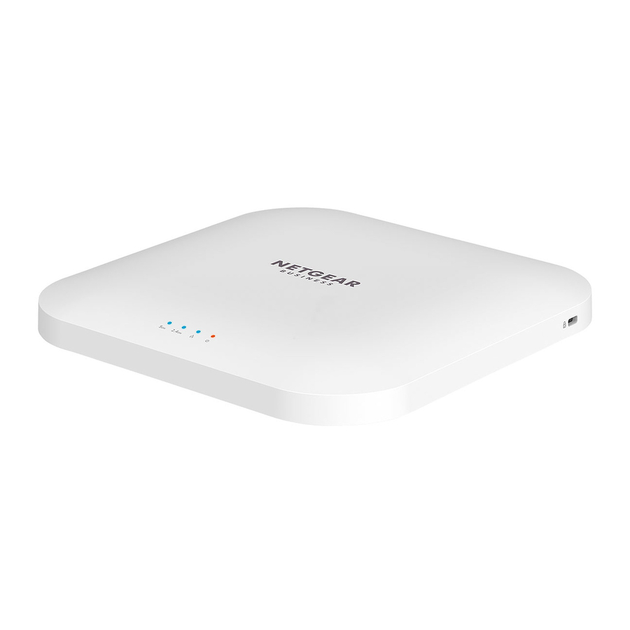
Overview

- 5 GHz WLAN LED
- 4 GHz WLAN LED
- LAN LED
- Power LED
- Reset button
- LAN/PoE+ port
- DC power connector
Step 1. Connect the WAX218
Power up the WAX218 access point by connecting the LAN/PoE+ port to a PoE+ switch that supplies 802.3at (PoE+) power.
The WAX218 LAN/PoE+ port supports Ethernet speeds up to 2.5 Gbps. The following figure shows a NETGEAR MS510TXPP switch, which supports speeds of 2.5 Gbps and higher. However, if your Internet connection, modem, and switch support a speed of 1 Gbps (which is a common speed), the access point LAN connection functions at 1 Gbps.
Sample connections

Step 2. Join the default WiFi network
The default WiFi network name (SSID) for the WAX218 is "WAX218XXXXXX‑CONFIGONLY," where XXXXXX represents the last 6 characters of the device's MAC Address, as printed on the access point label. By default, the access point WiFi network provides WPA2 security.
Note: The default WiFi turns off if it is idle for 15 minutes.
Join the WiFi network
- On the WiFi device that you want to connect to the WAX218, open the software utility that manages your WiFi connections. The utility scans for all WiFi networks in your area.
- Find and select the access point's WiFi network name (SSID) and connect to its WiFi network.
The default WiFi network name (SSID) for the WAX218 is "WAX218XXXXXXCONFIG‑ONLY." - Enter the unique passphrase printed on the product label.
Step 3. Log in to the local browser UI
- Launch a web browser and enter aplogin.net in the address field.
The login screen displays. - Your browser may display a security warning, which you can dismiss.
- The Day Zero login page displays. Follow the prompts. You must set a new admin password for local login, a new SSID, and a new passphrase.
Accept NETGEAR's terms and conditions. - Click the Apply button.
Your settings are saved, and you are disconnected from the WiFi network. - Reconnect to the WiFi network using the new SSID and new passphrase.
- Log in to the local browser UI using your new admin password.
![warning]() Note:If you cannot connect to the Internet, see the user manual for troubleshooting information and instructions on how to log in.
Note:If you cannot connect to the Internet, see the user manual for troubleshooting information and instructions on how to log in.
During installation and setup, the access point's LEDs can light in these colors:
| Power |  | Solid orange. The access point is powered on. |
| LAN |  | Solid blue. The LAN port detects a link with a powered‑on device. |
 | Blinking blue. The LAN port is transmitting or receiving data. | |
| 2.4 GHz WLAN | | Solid blue. The 2.4 GHz radio is operating without clients. |
| | Blinking blue. The 2.4 GHz radio is transmitting or receiving data. | |
| 5 GHz WLAN | | Solid blue. The 5 GHz radio is operating without clients. |
| | Blinking blue. The 5 GHz radio is transmitting or receiving data. |
Other setup methods
For more information on how to configure your device, see the user manual, which you can download by visiting www.netgear.com/support/product/WAX218
Support and Community
Visit netgear.com/support to get your questions answered and access the latest downloads.
You can also check out our NETGEAR Community for helpful advice at community.netgear.com.
Regulatory and Legal
If this product is sold in Canada, you can access this document in Canadian French at https://www.netgear.com/support/download/.)
For regulatory compliance information including the EU Declaration of Conformity, visit https://www.netgear.com/about/regulatory/.
See the regulatory compliance document before connecting the power supply.
For NETGEAR's Privacy Policy, visit https://www.netgear.com/about/privacy-policy.
By using this device, you are agreeing to NETGEAR's Terms and Conditions at https://www.netgear.com/about/terms-and-conditions. If you do not agree, return the device to your place of purchase within your return period.
Do not use this device outdoors. The PoE source is intended for intra building connection only.
Mounting options
You can mount the access point to a solid surface (a wall or a ceiling), or to a ceiling with a 15/16 in. (23.8 mm) T-bar, or you can install the access point freestanding on a flat surface.
We recommend that you use a flat Ethernet cable so that the cable fits in the narrow space between the access point and the surface on which it is mounted or placed.
Mount to a solid wall
The bottom of the access point includes two holes that let you mount the access point on two screws inserted in a wall.

- Mark the wall where you want to insert the provided anchors and screws, which must be 3.875 in. (98.5 mm) apart, and insert the anchors and screws.
![]()
Leave about 0.25 in. (6 mm) of each screw protruding from the wall so that you can insert the screws into the holes on the bottom of the access point.
- Line up the holes on the bottom of the access point with the screws in the wall and mount the access point to the wall.


Mount to a T-bar
- Slide the 15/16 in. (23.8 mm) bracket between the guides on the bottom of the access point until it locks in place. The locking tab must be at the front of the access point.

- Hold the access point upside down.
![warning]() Note: If you can reach behind the T‑bar, hold the T‑bar with one hand and the access point with your other hand.
Note: If you can reach behind the T‑bar, hold the T‑bar with one hand and the access point with your other hand. - Align the rectangular protruding part of the bracket with the T‑bar.
- Hook the bracket onto one side of the T‑bar.
- Hook the bracket onto the other side of the T‑bar until the bracket locks onto the T‑bar.


Mount to a solid ceiling
- Using the anchors and screws provided, attach the 15/16 in. (23.8 mm) bracket with the screw holes to the ceiling.
The rectangular protruding part of the bracket must be facing the ceiling.
![]()
- Hold the access point upside down with the front of the access point facing the bracket. Then, line up the guides on the bottom of the access point with the bracket.

- Slide the access point into the bracket until it locks in place. The locking tab must be at the front of the access point.


Note: To unlock the access point, push the locking tab toward the ceiling and slide the access point out of the bracket.

NETGEAR, Inc.
350 East Plumeria Drive
San Jose, CA 95134, USA
NETGEAR INTERNATIONAL LTD
Floor 1, Building 3,
University Technology Centre
Curraheen Road, Cork,
T12EF21, Ireland
© NETGEAR, Inc., NETGEAR and the NETGEAR Logo are trademarks of NETGEAR, Inc. Any non‑NETGEAR trademarks are used for reference purposes only.
 |
Documents / Resources
References
WAX218 | WiFi 6 Access Point | NETGEAR Support
Regulatory | NETGEAR
NETGEAR Support | NETGEAR
WAX218 | WiFi 6 Access Point | NETGEAR Support
English - NETGEAR Communities
Download Center | Downloads and Documentation | NETGEAR
Regulatory | NETGEAR
NETGEAR Privacy Policy | NETGEAR
NETGEAR Terms and Conditions | NETGEAR
Download manual
Here you can download full pdf version of manual, it may contain additional safety instructions, warranty information, FCC rules, etc.
Advertisement
Thank you! Your question has been received!


Need Assistance?
Do you have a question about the WAX218 that isn't answered in the manual? Leave your question here.