Advertisement
Package contents

 NOTE: You can power up the WAX220 by connecting it to a PoE switch or to a power adapter. If you purchased a WAX220 SKU without an included power adapter, you can purchase one separately.
Overview

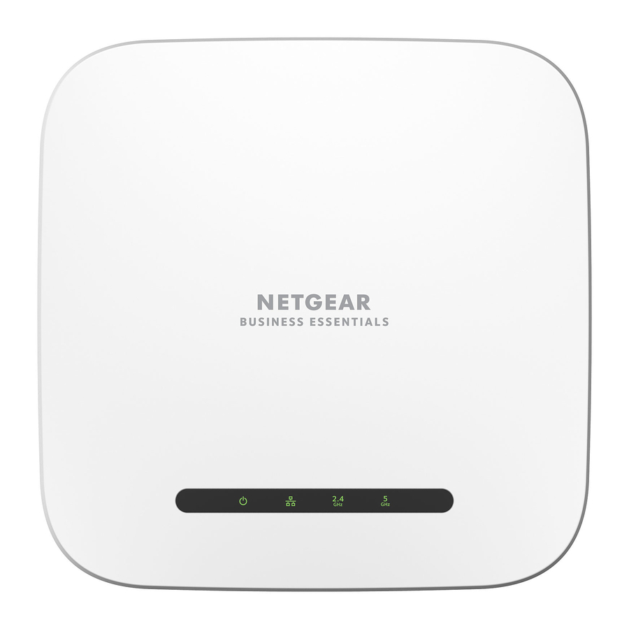
- Power LED
- LAN LED
- 2.4 GHz WLAN LED
- 5 GHz WLAN LED
- DC power connector
- Reset button
- LAN/PoE+ port
Start Here:
Step 1. Connect the WAX220 to your network
Power up the WAX220 access point (AP) using one of the following methods:
- Use a PoE+ switch: Connect one end of an Ethernet cable to the LAN/PoE+ port of the AP and connect the other end to a PoE+ switch that supplies 802.3at PoE+ power. The power LED on the AP lights.
- Use a power adapter: Connect the power adapter's DC plug to the AP, and insert the power adapter in a power outlet. The power LED on the AP lights.


NOTE:
- WiFi and wireless have the same meaning.
- To fully realize the benefits of WiFi 6 network speeds and bandwidth, use a 2.5 Gbps/ Multi‑gigabit switch with at least PoE+ to connect and power the AP. Connecting to a gigabit switch or using PoE (802.3af) limits performance.
During installation and setup, the AP's LEDs can light in these colors:
| Power |  | Solid amber: The AP is starting up. If the LED remains solid amber, the PoE power is not at the required 802.3at (PoE+) level. |
| Blinking amber: The firmware is being updated, or the AP cannot detect a DHCP server. | ||
| Solid green: The AP is powered on and ready. | ||
| LAN |  | Solid or blinking green: The LAN port detects a 2.5 Gbps link with a powered‑on device. |
| Solid or blinking amber: The LAN port detects a 1 Gbps or 100 Mbps link with a powered-on device. | ||
| 2.4 GHz WLAN |  | Solid green: The 2.4 GHz radio is operating without clients. |
| Solid or blinking blue: The 2.4 GHz radio is operating with clients | ||
| 5 GHz WLAN |  | Solid green: The 5 GHz radio is operating without clients. |
| Solid or blinking blue: The 5 GHz radio is operating with clients. |
NOTE:
The AP supports two types of WiFi networks (SSIDs):
- Management WiFi network: The special purpose WiFi network that you use to access the AP's device UI to configure and manage the AP. You can use the QR code or WiFi network information on the AP label to connect to the management WiFi network. To protect your WiFi network security, the management WiFi network does not let you connect to the Internet.
- User WiFi network: The WiFi network that provides general network access to authenticated users. During set up, you must configure the first user WiFi network. After you complete the initial setup process, you can configure up to three additional WiFi networks.
Step 2. Set up Internet access and connect
When you power up your new AP, the management WiFi network becomes active. We recommend that you use a WiFi‑enabled computer to connect to the management WiFi network for setup.
NOTE: For security reasons, the management WiFi network turns off when inactive for 15 minutes. If this happens during setup, press the Reset button for 20 seconds to reset the AP to default settings.
- Connect your computer or tablet to the AP's management WiFi network (SSID) using one of the following methods:
- Scan the QR code: Scan the QR code on the AP label to connect to the management WiFi network.
- Connect manually: The management WiFi network is on the AP label.
The default network key (password) for WiFi access is also on the AP label. The default name of the management WiFi network is printed on the AP's label. The WiFi network name uses the format "WAX220XXXXXX-CONFIG-ONLY," where XXXXXX is customized to every device (based on the last six digits of the MAC address).
- Launch a web browser and enter https://www.aplogin.net in the address field.
Use https, not http. Note that https://www.aplogin.net is the same as https://192.168.0.100.
NOTE:
- Your browser might display a security warning because of the self-signed certificate on the AP, which is expected behavior. You can proceed, or add an exception for the security warning. For more information, see kb.netgear.com/000062980/.
- If your browser redirects to a www.netgear.com page, your computer or tablet is not connected to the AP's management WiFi network, and you must repeat the previous step.
The Welcome page for the setup process displays.
- Click the Next button.
- Set a new AP login password, and for your first user WiFi network, set a WiFi network name and password.
- Click the Apply button.
Your settings are saved and the AP restarts. This process takes about two minutes.
You are done. The AP is connected to the network and ready to use. You can now connect a computer or mobile device to the user WiFi network that you just set up, using the WiFi password that you just defined.
For more information, including information about how to log in to the AP's device UI to change the AP's settings and update the firmware, see the user manual, which you can download by visiting netgear.com/support/download and entering WAX220 in the search field.
Mounting options
You can mount the AP to a wall or to a ceiling with a 15/16 in. (24 mm) T-bar, or you can install the AP freestanding on a flat surface.
We recommend that you use a flat Ethernet cable so that the cable fits in the narrow space between the AP and the surface on which it is mounted or placed.
Before you mount the AP, first set up and test the AP to verify WiFi network connectivity.
Mount to a solid wall


Make sure that the wall is not damaged. For example, water damage can destroy a drywall.
- Place the mounting plate on the wall. The latch on the mounting plate must face downward.
- Mark the wall where the mounting holes are.
- Using a 3/16 in. (4.7 mm) drill bit, drill holes in the wall.
- Tap each anchor into the wall with a soft mallet until the anchors are flush with the wall.
- Use the screws to attach the mounting plate to the wall.
![warning]() NOTE: Unless you insert the screws into a wall stud, do not insert the screws into the wall without anchors.
NOTE: Unless you insert the screws into a wall stud, do not insert the screws into the wall without anchors.


- Connect cables to the AP.
- Hold the AP at approximately a 45-degree angle, as shown in the figure to the left, and attach it to the mounting plate.

- Twist the AP clockwise to lock it onto the mounting plate. The opening at the bottom of the mounting plate latch locks onto the knob at the bottom of the AP.

Mount to a T-bar
- Slide the T‑bar partially into the metal bracket.
- Attach the metal bracket to the ceiling bar.
- Push the T‑bar over the ceiling bar.

- Use the lock screw to lock the metal bracket into place.
- Use the four short screws to attach the mounting plate to the T‑bar.

- Connect an Ethernet cable, or both an Ethernet cable and power adapter, to the AP before mounting.
The AP is designed to be unobtrusive, so it sits flat on the ceiling surface when it is mounted.

- Hold the AP upside down at approximately a 45‑degree angle, as shown in the figure to the right, and attach it to the mounting plate. When viewed from the front, the latch points towards the lower left corner of the AP.
- Twist the access point clockwise to lock it onto the mounting plate.
The opening at the bottom of the mounting plate latch locks onto the knob at the bottom of the AP. In final position, the latch points directly towards the center bottom edge of the AP.
See the figure to the right, and the figures in the next column. the mounting plate.


The AP is in position and locked onto the mounting plate.

Unmount the AP
Make sure you hold the AP so that it does not drop when you release it from the mounting plate.
- Place your thumb on the locking latch, located behind the LEDs on opposite side of the AP.
- Press the latch towards the T‑bar or wall to release the lock and keep the lock open.

- Turn the AP counterclockwise approximately 45 degrees until the AP releases from the mounting plate.
The mounting plate remains attached to the T‑bar or the wall.


Support and Community
Visit netgear.com/support to get your questions answered and access the latest downloads.
You can also check out our NETGEAR Community for helpful advice at community.netgear.com.
NETGEAR, Inc. September 2022
350 East Plumeria Drive
San Jose, CA 95134, USA
NETGEAR INTERNATIONAL LTD
Floor 1, Building 3,
University Technology Centre
Curraheen Road, Cork,
T12EF21, Ireland
© NETGEAR, Inc., NETGEAR and the NETGEAR Logo are trademarks of NETGEAR, Inc. Any non‑NETGEAR trademarks are used for reference purposes only.

Documents / Resources
References
Access Point Login
What do I do if I my browser displays a security message? | Answer | NETGEAR Support
NETGEAR: Advanced WiFi & Networking
NETGEAR Support | NETGEAR
English - NETGEAR Communities
Download manual
Here you can download full pdf version of manual, it may contain additional safety instructions, warranty information, FCC rules, etc.
Advertisement
Thank you! Your question has been received!


Need Assistance?
Do you have a question about the WAX220 that isn't answered in the manual? Leave your question here.