Table of Contents
Advertisement
Quick Links
Advertisement
Table of Contents

Related Manuals for Honeywell HCE 40


Summary of Contents for Honeywell HCE 40
- Page 1 Storey Controller HCE 40 Installation and Operation...
-
Page 3: Table Of Contents
Contents Contents Overview Application Installation procedure Creating zoning plan Installing Configuring and making electrical connections Start-up Creating zoning plan Determining temperature zones Filling out zoning plan Installation Wall installation Installation on DIN rails Installing storey controller components Description Layout of circuit board LED indicators on storey controller Operating modes of storey controller Buttons on storey controller... - Page 4 Contents Setting actuator Switching between heating/cooling Cabling connections Start-up Starting up storey controller Start-up with central operating device Assigning setpoint adjusters of type HCU 23 or HCW 23 to a zone Removing assignment Saving settings at central operating device Checking installation Completing start-up Resetting storey controller to state of delivery Appendix...
-
Page 5: Overview
(see "Overview of heating components" Page 50). The storey controller HCE 40 is hard-wired to setpoint adjusters of type HCU 23 or HCW 23, room temperature sensors of type RF 20 or the central operating device HCM 100. -
Page 6: Installation Procedure
• Determining which heating circuits* are controlled by the storey controller. Installing • Installing the components of the storey controller HCE 40. Configuring and making electrical connections • Setting the storey controller to the actuator type, attaching cables to the respective connections and connect components together. -
Page 7: Creating Zoning Plan
Damage caused by equipment from other manu- facturers! The storey controller was designed for use with Caution! components from Honeywell only! Use only H 200 AG (normally closed) or H 200 AO ► (normally open)-type actuators. Group actuators (by type and location) which are controlled with the ►... -
Page 8: Filling Out Zoning Plan
Creating zoning plan If more than 5 temperature zones or 10 actuators are present: Determine the number of additional storey controllers required using ► the following table: Temperature Actuators No. of storey zones (maximum) (maximum) controller Hint: The example at the end of this section shows zone divisions with corresponding zoning plan. - Page 9 Creating zoning plan Example of zone divisions This example shows: • A home divided into five temperature zones. • Bathroom and WC are controlled by one setpoint adjuster. One temperature zone is sufficient for three actuators. • The maximum number of actuators (10 per storey controller) is used to the full with the storey controller.
- Page 10 Creating zoning plan The example yields the following zoning plan: Temper- Actuator Setpoint Room name ature zone (type, location) adjuster at operating (location) device Heating loop 1 Living room "Living" (living room) Zone 1 Heating loop 2 (living room) Heating loop 1 (dining Dining room "Dining"...
- Page 11 Creating zoning plan...
-
Page 12: Installation
Installation Installation The storey controller is sensitive to excessive temperatures! When selecting the location for operation, ensure Caution! ► that the ambient temperature in that area does not exceed 50 °C. The storey controller was designed for installation in a distributor box. If insufficient space is available there, select a location free of humidity and moisture. -
Page 13: Wall Installation
Installation Wall installation Four 4.2-mm holes for installation are located on the storey controller. Dimensions of storey controller in mm ø4.2 Mark, drill and insert plugs into fastening holes. ► Screw on the storey controller. ►... -
Page 14: Installation On Din Rails
Installation Installation on DIN rails Place housing on the ► Á DIN rail from below (1). Press upper edge of ► housing toward the wall until it snaps into place (2). À Installing storey controller components Install components as described in the accompanying installation ►... -
Page 15: Description
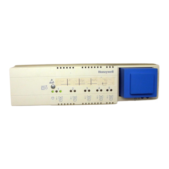
Description Description Layout of circuit board 6. Connection for temperature zone 4 1. Connector (1 to 12) 7. Connection for temperature zone 3 2. Connector (13 to 25) 8. Connection for temperature zone 2 3. Switch used to branch out temperature zones (Page 20) 9. -
Page 16: Led Indicators On Storey Controller
Description LED indicators on storey controller The LEDs on the storey controller indicate the operating mode of the storey controller and the installed temperature zones. Normal mode / (green) Power-on indicator Connected setpoint adjuster / (red) Fault indication: wire break or short circuit Position of the actuators / Assignment of temperature zones / (green) -
Page 17: Operating Modes Of Storey Controller
Description Operating modes of storey controller Normal mode In normal mode the green LEDs provide information on the position of the actuators: Illuminating Mains voltage connected (green) Mains voltage not connected Flashing Room sensor or setpoint adjuster connection faulty. (red) Illuminating Thermal actuator opened Flashing... - Page 18 Description Installation mode • In installation mode, temperature zones are assigned to the central operating device. Refer to Section "Start-up with central operating device" on Page 36. Device display (configuration button 1) • The device display informs you of the configuration of your storey controller system, i.e.
-
Page 19: Buttons On Storey Controller
Description Buttons on storey controller • Configuration button (1): Display of the assignment of temperature zones to the central operating device. Selection of the temperature zone which is to be assigned to the central operating device or a check setpoint adjuster (see Button... - Page 20 Description Button functions assignment storey Press the configuration ► controller to the central operating button (1) briefly. device, setpoint adjusters and room temperature sensors is displayed. The storey controller shows up in the device display. The green LED illuminates if a temperature zone is assigned to the central operating device.
-
Page 21: Configuration And Electrical Connection
Configuration and electrical connection Configuration and electrical connection Unplug the power plug before opening the housing. ► Damage to exposed components! The electronic components of the storey controller can Caution! be damaged by static electricity discharge! Do not touch such components. ►... -
Page 22: Branching Out Time Programs
Configuration and electrical connection Branching out time programs You can use the setpoint and temperature input* of zone one as source for other zones. The branching is be done by the selector switch (1). 1. Switch used to assign tem- À... - Page 23 Configuration and electrical connection Switch Property position A setpoint and temperature input is assigned to each temperature zone. The setpoint and temperature input of temperature zone 1 is also valid for temperature zone 2. The setpoint and temperature input of temperature zone 1 is also valid for temperature zones 2 and 3.
-
Page 24: Setting Actuator
Configuration and electrical connection Setting actuator Only one type of actuator can be connected to a storey controller at a time. If actuators which are open with current and actuators which are closed with current are to be used, two storey controllers with the respective suitable controller are required. -
Page 25: Switching Between Heating/Cooling
Configuration and electrical connection Set the switch according to the following table. ► Switch Actuator type Property position Normally closed Opens the heating circuit when the actuator is H 200 AG supplied with current. Normally open Opens the heating circuit when the actuator is not H 200 AO supplied with current. -
Page 26: Cabling Connections
Configuration and electrical connection Cabling connections Permissible cable types and lengths Cable (designation) Connection: Storey Max. permis- controller HCE 40 and - sible length Central operating device 56 m JE-Y(St)Y 2×2×0.8 HCE 100 Setpoint adjuster HCU 23 100 m MCR pre-regulator... - Page 27 Configuration and electrical connection Use only cables with wire diameters up to 1.5 mm . We recommend the cable type JE-Y(St)Y 2×2×0.8. Use the accompanying connector types and cables of sufficient length. Connecting actuators 3 actuators can be connected in temperature zones 1 to 3, and 2 actuators can be connected in temperature zones 4 and 5.
- Page 28 Configuration and electrical connection Zone ... Insert the connectors of the ► actuators into the sockets of the respective temperature zones. H 200–XX Squeeze the cables into the ► stress relief clamp. Break out the openings for ► the cables on the housing using a diagonal cutter.
- Page 29 Configuration and electrical connection Zone Allocation For device connections, the following zone allocation must be applied:...
- Page 30 Configuration and electrical connection Connecting central operating device The storey controller HCE 40 can control up to 10 actuators. However, no more than 3 actuators may be connected in any one temperature zone. Use cables in accordance with the table on Page 24.
- Page 31 Configuration and electrical connection 1. Central operating device HCM 100 2. Storey controller 1 À (connector 13 to 25) 3. Storey controller 2 (connector 13 to 25) 4. Storey controller 3 Storey controller 1 (connector 13 to 25) Á 16 17 20 21 5.
- Page 32 (terminal 5). Setpoint adjuster HCW 23 Example: Connection to temper- À ature zone 5 1. Setpoint adjuster HCW 23 2. Storey controller HCE 40 (connector 13 to 25) 16 17 Á 3. Temperature zone 5 Â...
- Page 33 Configuration and electrical connection Setpoint adjuster HCU 23 1. Setpoint adjuster HCU 23 5. Storey controller HCE 40 (connector 13 to 25) 2. HAC 30 (window contact) 6. Temperature zone 5 3. Connection of the temperature zones 1 to 5 Temperature selector input 4.
- Page 34 With controllers MCR 35 and MCR 40, the temperature selector and ground inputs are found on the following terminals: 1. MCR 35 À Low-voltage side 2. Ground input HCE 40 terminal 17 Á  3. Temp. selector input à HCE 40 terminal 16 4.
- Page 35 Configuration and electrical connection If control cables for heating ("boiler feedback") and for the pump relay are available: Use cables in accordance with the table on Page 24. ► Connect boiler feedback and pump relay to storey controller as ► shown in the following diagram.
- Page 36 Configuration and electrical connection Connecting setpoint adjuster and room temperature sensor Setpoint adjusters of type HCW 23 and HCU 23 and room temperature sensors of type RF 20 are hard-wired. Connect the setpoint adjuster and room temperature sensor in ► accordance with the accompanying installation instructions.
-
Page 37: Start-Up
Start-up Start-up Setpoint adjusters, room temperature sensors or the central operating device are assigned to the temperature zones of the storey controller at start-up. A room name is defined at the central operating device (if present) for each temperature zone. Starting up storey controller Plug in power plug. -
Page 38: Start-Up With Central Operating Device
Start-up Start-up with central operating device This section covers start-up with the central operating device. Setpoint adjusters and room names are assigned to the individual zones. This section can be ignored if you have not installed a central operating device. Dial button (1) Press Activates the cursor... - Page 39 Start-up Assigning temperature zones Setpoint adjusters or room temperature sensors which are used are already assigned (fixed) via their wiring. Example: Assigning room name LIVING to zone 1 Press the configuration button (1) on the storey controller. ► Assignment of the storey controller to the central operating device is displayed.
- Page 40 Start-up The central operating device is in Works setting automatic mode. The display on the WE 28.07.97 11:15 central operating device shows the standard display, for example: No Lifestyle active LIVING 20.0 C Press the Dial button. ► Please check the clock The following text is displayed: TU 29.05.01 11:15 No Lifestyle active...
- Page 41 Start-up Select the "Settings" submenu and ► INSTALLATION press the Dial button. DE-INSTALLATION The following text is displayed: SUMMER TIME PARAMETERS Select the "Installation" submenu ► LIVING and press the Dial button. DINING The following text is displayed: KITCHEN BEDROOM Turn the Dial button until "LIVING"...
-
Page 42: Assigning Setpoint Adjusters Of Type Hcu 23 Or Hcw
See "Removing assignment". Removing assignment Removing temperature zone on HCE 40 If you would like to remove a temperature zone, e.g. if it was assigned accidentally or a setpoint adjuster has been uninstalled and is no... - Page 43 Start-up Press the configuration button (1) repeatedly until the red or green ► LED of the relevant temperature zone flashes. The red LED of the temperature zone flashes. Press the delete button (2) until the red or green LED goes out.The ►...
- Page 44 Start-up Deleting assignment of a room name at central operating device Change to submenu "Settings", as ► INSTALLATION described on Page 39. DE-INSTALLATION The following text is displayed: SUMMER TIME PARAMETERS Select the "De-Installation" submenu ► LIVING and press the Dial button. DINING A list of the assigned room names KITCHEN...
-
Page 45: Saving Settings At Central Operating Device
Start-up Saving settings at central operating device Before start-up is completed, the settings at the central operating device must be saved. The method for saving settings is described in the operating instructions of the central operating device. Checking installation Configuration Press the configuration button (1) briefly. -
Page 46: Completing Start-Up
Start-up Checking assignment of room names Maximise setpoint temperature at the central operating device (see ► operating instructions of central operating device). The green LED of the assigned temperature zone illuminates. Actuators which are normally closed may experience a delay of 15 minutes. -
Page 47: Resetting Storey Controller To State Of Delivery
Start-up Resetting storey controller to state of delivery All current assignments are lost if the storey controller is reset to the state of delivery. Press the configuration button (1) twice briefly. ► Press and hold the delete button (2) for approx. 20 seconds until all ►... -
Page 48: Appendix
Thermal actuator Central operating device Opens and closes a heating Central operating device HCM 100 circuit. Controlled by the storey of the storey controller HCE 40. controller. Boiler feedback Time program The storey controller HCE 40 Defined combination of setpoints... -
Page 49: Help With Problems
Appendix Help with problems Problem Cause/Solution Mains voltage not connected. does not illuminate when power Check whether electricity is available at ► plug is plugged in. outlet. Red LED flashes in Connection of setpoint adjuster or room normal mode. temperature sensor faulty. Ensure correct cabling to setpoint adjuster ►... - Page 50 Appendix Problem Cause/Solution Check heating and inlet temperature. Not all rooms are ► heated. Check adjuster on thermal actuator (see ► "Setting actuator" on Page 22). Check actuator for correct operation. ► All rooms to cold or all Check fuse (4 A, fast) inside of the ►...
- Page 51 Appendix...
-
Page 52: Overview Of Heating Components
Central operating device HCM 100 Central operating device of the storey controller system Storey controller HCE 40 Controls actuators of floor heating/radiators; communicates with setpoint adjusters and room temperature sensors Room temperature sensor RF 20 for storey controller... -
Page 53: Zoning Plan
Appendix Zoning plan Zone Actuator Setpoint adjuster Room name (location) (type, location) - Page 54 • only one type of thermal actuator per storey controller (open with current or closed with current) • max. 3 storey controllers of type HCE 40 can be connected to one central operating device HCM 100. • If a central operating device HCM 100 is installed, maximum one setpoint adjuster HCU 23 can be connected to the storey connector HCE 40.
- Page 56 Honeywell AG Böblinger Straße 17 D – 71101 Schönaich Tel. (+49) (0) 1801 466 390 This company is certificated to The right is reserved to make modifications. This document is definitive for the enclosed product and replaces all previous publications.