Cisco ISA 3000 Connecting Instructions
Hide thumbs
Also See for ISA 3000:
- Quick start manual (12 pages) ,
- Product documentation (12 pages) ,
- Manual (6 pages)
Table of Contents
Advertisement
Quick Links
Connecting the Cisco ISA 3000
This chapter describes how to connect the Cisco ISA 3000 to Ethernet devices and a network.
•
•
•
•
•
•
•
•
•
Preparing to Connect the Cisco ISA 3000
Before you connect the Cisco ISA 3000 to the devices, install the ISA 3000 according to the instructions in
Installing the Cisco ISA 3000 Industrial Security
Warning
Caution
Preventing Damage to the Cisco ISA 3000
Before installation, observe these general guidelines:
• Proper ESD protection should be observed
• Ensure the device is properly grounded
Preparing to Connect the Cisco ISA 3000, on page 1
Preventing Damage to the Cisco ISA 3000, on page 1
Connecting to DC Power, on page 3
Verifying Connections, on page 7
Connecting Alarm Circuits, on page 8
Wiring the External Alarms, on page 9
Attaching the Alarm Connector to the Device, on page 11
To avoid electric shock, do not connect safety extra-low voltage (SELV) circuits to telephone-network
voltage (TNV) circuits. LAN ports contain SELV circuits, and WAN ports contain TNV circuits. Some
LAN and WAN ports both use RJ-45 connectors. Use caution when connecting cables. Statement 1021
If this product will be installed in a hazardous location, read the Getting Started/Printed Document of
Compliance included in the package.
Appliance.
Connecting the Cisco ISA 3000
1
Advertisement
Table of Contents

Related Manuals for Cisco ISA 3000


Summary of Contents for Cisco ISA 3000
-
Page 1: Table Of Contents
Attaching the Alarm Connector to the Device, on page 11 Preparing to Connect the Cisco ISA 3000 Before you connect the Cisco ISA 3000 to the devices, install the ISA 3000 according to the instructions in Installing the Cisco ISA 3000 Industrial Security Appliance. -
Page 2: Connecting A Pc To The Cisco Isa 3000 For Configuration
There are two methods of connecting to the Cisco ISA 3000 in case of troubleshooting: • Connect a PC to the console connector of the Cisco ISA 3000 and launch a console terminal to use the CLI. ASA has a full CLI set, however, FTD only supports a setup script plus a few commands. -
Page 3: Connecting To Dc Power
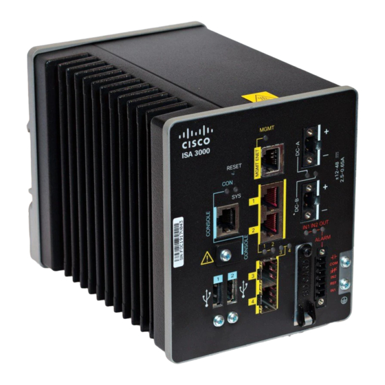
Figure 2: mini-USB Cover Step 3 Connect the mini-USB side of a cable to the USB Console port on the Cisco ISA 3000. Step 4 Connect the opposite end of the mini-USB cable to the USB port on your PC. If your PC warns you that you do not have the proper drivers to communicate with the device, you can obtain them from your computers manufacturer, or go here: https://software.cisco.com/download/home/282774227/type/282855122/release/3.1... - Page 4 DC source with the higher voltage. If one of the two power sources fail, the other continues to power the device. To connect DC power to your Cisco ISA 3000, follow these steps: Step 1 Locate the two power connectors on the device front panel labeled DC-A and DC-B.
- Page 5 Connecting the Cisco ISA 3000 Connecting to DC Power Step 4 Using a 18-gauge (1.02mm) wire-stripping tool, strip the ground wire and both ends of the twisted pair wires to 0.25 inch (6.3 mm) ± 0.02 inch (0.5 mm). See the following figure, number 1. Do not strip more than 0.27 inch (6.8 mm) of insulation from the wires.
-
Page 6: Attaching The Dc Power Connectors To The Device
Connecting the Cisco ISA 3000 Attaching the DC Power Connectors to the Device Figure 6: Torquing the Power Connector Captive Screws Power connector captive screws Warning An exposed wire lead from a DC-input power source can conduct harmful levels of electricity. Be sure that no exposed portion of the DC-input power source wire extends from the power and relay connector. -
Page 7: Verifying Connections
For example, use tie wraps to secure the wires to the rack. Verifying Connections To verify that all devices are properly connected to the Cisco ISA 3000, first turn on all the connected devices, then check the LEDs. To verify Cisco ISA 3000 operation, refer to the following table:... -
Page 8: Connecting Alarm Circuits
Connecting the Cisco ISA 3000 Connecting Alarm Circuits Activity Description Alarm Out Alarm monitoring Off — Alarm Out not configured or the system is off (Default) Green Steady on — Alarm Out is configured, no alarm detected. Red Steady on — Minor alarm detected Red Flashing —... -
Page 9: Wiring The External Alarms
Connecting the Cisco ISA 3000 Wiring the External Alarms signal. An alarm output and the common wiring connection are required to complete a single alarm output circuit. The alarm connectors are on the device panel and are detailed in the following table:... - Page 10 Connecting the Cisco ISA 3000 Wiring the External Alarms IN1 - External device connection 1 REF - External device connection 2 Step 5 Use a ratcheting torque flathead screwdriver to tighten the alarm connector captive screw (above the installed wire leads) to 2 in-lb (0.23 N-m).
-
Page 11: Attaching The Alarm Connector To The Device
Connecting the Cisco ISA 3000 Attaching the Alarm Connector to the Device Figure 7: Completed Connections for Two External Alarm Devices on the Alarm Connector IN1 wired connection REF wired connection COM wired connection NO wired connection Attaching the Alarm Connector to the Device... - Page 12 Connecting the Cisco ISA 3000 Attaching the Alarm Connector to the Device Step 2 Use a ratcheting torque flathead screwdriver to tighten the captive screws on the sides of the alarm connector. Torque to 2 in-lb (0.23 N-m). Connecting the Cisco ISA 3000...