Cisco ISA550 Administration Manual
Isa500 series integrated security appliances
Hide thumbs
Also See for ISA550:
- Quick start manual (13 pages) ,
- Administration manual (16 pages) ,
- Administration manual (371 pages)

Related Manuals for Cisco ISA550


Summary of Contents for Cisco ISA550
- Page 1 ADMINISTRATION GUIDE Cisco Small Business ISA500 Series Integrated Security Appliances (ISA550, ISA550W, ISA570, ISA570W)
- Page 2 Cisco and the Cisco logo are trademarks or registered trademarks of Cisco and/or its affiliates in the U.S. and other countries. To view a list of Cisco trademarks, go to this URL: www.cisco.com/go/trademarks. Third-party trademarks mentioned are the property of their respective owners. The use of the word partner does not imply a partnership relationship between Cisco and any other company.
- Page 3 (For ISA550 and ISA550W) This equipment has been tested and found to comply with the limits for a Class B digital device, pursuant to Part 15 of the FCC Rules.
- Page 4 The availability of some specific channels and/or operational frequency bands are country dependent and are firmware programmed at the factory to match the intended destination. The firmware setting is not accessible by the end user. Industry Canada statement: This device complies with RSS-210 of the Industry Canada Rules. Operation is subject to the following two conditions: (1) This device may not cause harmful interference, and (2) this device must accept any interference received, including interference that may cause undesired operation.
- Page 5 Conformément à la réglementation d'Industrie Canada, le présent émetteur radio peutfonctionner avec une antenne d'un type et d'un gain maximal (ou inférieur) approuvé pourl'émetteur par Industrie Canada. Dans le but de réduire les risques de brouillage radioélectriqueà l'intention des autres utilisateurs, il faut choisir le type d'antenne et son gain de sorte que lapuissance isotrope rayonnée équivalente (p.i.r.e.) ne dépasse pas l'intensité...
- Page 6 Validating Security License Enabling Bonjour and CDP Discovery Protocols Configuring Remote Administration Configuring Physical Ports Configuring the Primary WAN Configuring the Secondary WAN Configuring WAN Redundancy Configuring Default LAN Settings Configuring DMZ Cisco ISA500 Series Integrated Security Appliances Administration Guide...
- Page 7 Configuring SSL VPN Group Policy Configuring SSL VPN User Groups Viewing SSL VPN Summary Using the Site-to-Site VPN Wizard to Configure Site-to-Site VPN Starting the Site-to-Site VPN Wizard Configuring VPN Peer Settings Configuring IKE Policies Cisco ISA500 Series Integrated Security Appliances Administration Guide...
- Page 8 Chapter 3: Status Device Status Dashboard Network Status Status Summary Traffic Statistics Usage Reports WAN Bandwidth Reports ARP Table DHCP Bindings STP Status CDP Neighbor Wireless Status (for ISA550W and ISA570W only) Wireless Status Cisco ISA500 Series Integrated Security Appliances Administration Guide...
- Page 9 Configuring WAN Settings for Your Internet Connection Configuring WAN Redundancy Dual WAN Settings Configuring Link Failover Detection Load Balancing with Policy-Based Routing Configuration Example Configuring Dynamic DNS Measuring and Limiting Traffic with the Traffic Meter Cisco ISA500 Series Integrated Security Appliances Administration Guide...
- Page 10 Mapping CoS to LAN Queue Mapping DSCP to LAN Queue Configuring Default CoS Configuring Wireless QoS Default Wireless QoS Settings Configuring Wireless QoS Classification Methods Mapping CoS to Wireless Queue Mapping DSCP to Wireless Queue Cisco ISA500 Series Integrated Security Appliances Administration Guide...
- Page 11 Advanced Radio Settings Chapter 6: Firewall Configuring Firewall Rules to Control Inbound and Outbound Traffic About Security Zones Default Firewall Settings Priorities of Firewall Rules Preliminary Tasks for Configuring Firewall Rules General Firewall Settings Cisco ISA500 Series Integrated Security Appliances Administration Guide...
- Page 12 Configuring MAC Address Filtering to Permit or Block Traffic Configuring IP-MAC Binding to Prevent Spoofing Configuring Attack Protection Configuring Session Limits Configuring Application Level Gateway Chapter 7: Security Services About Security Services Cisco ISA500 Series Integrated Security Appliances Administration Guide...
- Page 13 Configuring Application Control Policy Mapping Rules Updating Application Signature Database Advanced Application Control Settings Configuring Spam Filter Configuring Intrusion Prevention Configuring Signature Actions Updating IPS Signature Database Configuring Web Reputation Filtering Configuring Web URL Filtering Cisco ISA500 Series Integrated Security Appliances Administration Guide...
- Page 14 Benefits of the Teleworker VPN Client Feature Modes of Operation Client Mode Network Extension Mode General Teleworker VPN Client Settings Configuring Teleworker VPN Client Group Policies Configuring SSL VPN Elements of the SSL VPN Cisco ISA500 Series Integrated Security Appliances Administration Guide...
- Page 15 Using Local Database and RADIUS Server for User Authentication Using LDAP for User Authentication Using Local Database and LDAP for Authentication Configuring RADIUS Servers Chapter 10: Device Management Viewing System Status Viewing Process Status Viewing Resource Utilization Administration Cisco ISA500 Series Integrated Security Appliances Administration Guide...
- Page 16 Sending Contents for System Diagnosis Configuring System Time Configuring Device Properties Diagnostic Utilities Ping Traceroute DNS Lookup Packet Capture Device Discovery Protocols UPnP Discovery Bonjour Discovery CDP Discovery LLDP Discovery Firmware Management Viewing Firmware Information Cisco ISA500 Series Integrated Security Appliances Administration Guide...
- Page 17 Testing the LAN Path from Your PC to Your Security Appliance Testing the LAN Path from Your PC to a Remote Device Appendix B: Technical Specifications and Environmental Requirements Appendix C: Factory Default Settings Device Management User Management Networking Wireless Security Services Cisco ISA500 Series Integrated Security Appliances Administration Guide...
-
Page 18: Cisco Isa500 Series Integrated Security Appliances Administration Guide
Contents Firewall Reports Default Service Objects Default Address Objects Appendix D: Where to Go From Here Cisco ISA500 Series Integrated Security Appliances Administration Guide... -
Page 19: Getting Started
Getting Started This chapter provides an overview of the Cisco ISA500 Series Integrated Security Appliance and describes basic configuration tasks to help you configure your security appliance. It includes the following sections: • Introduction, page 20 • Product Overview, page 21 •... -
Page 20: Introduction
Getting Started Introduction Introduction Thank you for choosing the Cisco ISA500 Series Integrated Security Appliance, a member of the Small Business Family. The ISA500 Series is a set of Unified Threat Management (UTM) security appliances that provide business-class security gateway solutions with dual WAN, DMZ, zone-based firewall, site-to-site and... -
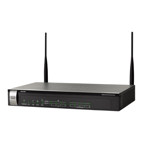
Page 21: Product Overview
Small Business SPEED LINK /ACT POWER/SYS WLAN CONFIGURABLE ISA570 Front Panel ISA570 Cisco Small Business SPEED LINK /ACT POWER/SYS CONFIGURABLE ISA570W Front Panel ISA570W Cisco Small Business SPEED LINK /ACT POWER/SYS WLAN CONFIGURABLE Cisco ISA500 Series Integrated Security Appliances Administration Guide... - Page 22 Flashes green when the USB device is transmitting and receiving data. WLAN Indicates the WLAN status. (ISA550W and • Solid green when the WLAN is up. ISA570W only) • Flashes green when the WLAN is transmitting and receiving data. Cisco ISA500 Series Integrated Security Appliances Administration Guide...
-
Page 23: Back Panel
ISA550 and ISA550W Back Panel Power Switch Reset ANT01 Button ANT02 12VDC A NT01 A NT02 L A N CONFIGURABLE WA N RESET POWER Power Connector Port Configurable Port Ports Ports Cisco ISA500 Series Integrated Security Appliances Administration Guide... - Page 24 Connects the unit to a USB device. You can use a USB device to save and restore system configuration, or to upgrade the firmware. Configurable Can be set to operate as WAN, LAN, or DMZ ports. ISA550 Ports and ISA550W have 4 configurable ports. ISA570 and ISA570W have 5 configurable ports.
-
Page 25: Getting Started With The Configuration Utility
This section includes the following topics: • Logging in to the Configuration Utility, page 26 • Navigating Through the Configuration Utility, page 27 • Using the Help System, page 28 • Configuration Utility Icons, page 28 Cisco ISA500 Series Integrated Security Appliances Administration Guide... -
Page 26: Logging In To The Configuration Utility
IP address to connect to the Configuration Utility. When the login page opens, enter the username and password. STEP 3 The default username is cisco. The default password is cisco. Usernames and passwords are case sensitive. Click Login. -
Page 27: Navigating Through The Configuration Utility
Click the title of a feature or sub-feature to open it. Main Content The main content of the feature or sub-feature appears in this area. Cisco ISA500 Series Integrated Security Appliances Administration Guide... -
Page 28: Using The Help System
Contract the sub-features of a feature in the left icon navigation pane or contract the items under a category. Connect icon Establish a VPN connection. Disconnect or Terminate a VPN connection or an active user Logout icon session. Cisco ISA500 Series Integrated Security Appliances Administration Guide... - Page 29 Check for Updates Check for new signature updates from Cisco’s Now icon signature server immediately. Credentials icon View the device credentials. Email Alerts icon View or configure the email alert settings. Cisco ISA500 Series Integrated Security Appliances Administration Guide...
-
Page 30: Factory Default Settings
VLAN Configuration: The security appliance predefines a native VLAN (DEFAULT) and a guest VLAN (GUEST). You can customize the predefined VLANs or create new VLANs for your specific business needs. See Configuring a VLAN, page 136. Cisco ISA500 Series Integrated Security Appliances Administration Guide... -
Page 31: Restoring The Factory Default Settings
Administrative Access: You can access the Configuration Utility by using a web browser from the LAN side and entering the default LAN IP address of 192. 1 68.75. 1 . You can log on by entering the username (cisco) and password (cisco) of the default administrator account. To prevent... -
Page 32: Performing Basic Configuration Tasks
Backing Up Your Configuration, page 34 Changing the Default Administrator Password The default administrator account (“cisco”) has full privilege to set the configuration and read the system status. For security purposes, you must change the default administrator password at the first login. -
Page 33: Upgrading Your Firmware After Your First Login
Do not repeat any password more than three times in a row. Do not set the password as the username or “cisco.” Do not capitalize or spell these words backwards. -
Page 34: Backing Up Your Configuration
PC or on a USB device. You must first download the latest firmware image from Cisco.com and save it to your local PC or to a USB device. See Upgrading Firmware from a PC or a USB Device, page 387. -
Page 35: Chapter 2: Configuration Wizards
Using the DMZ Wizard to Configure DMZ Settings, page 71 • Using the Wireless Wizard (for ISA550W and ISA570W only), page 76 To access the Configuration Wizards pages, click Configuration Wizards in the left hand navigation pane. Cisco ISA500 Series Integrated Security Appliances Administration Guide... -
Page 36: Using The Setup Wizard For The Initial Configuration
Using the Setup Wizard for the Initial Configuration Use the Setup Wizard to quickly configure the primary features of your security appliance, such as Cisco.com account credentials, security license, remote administration, port, WAN, LAN, DMZ, WAN redundancy, WLAN (for ISA550W and ISA570W only), and security services. -
Page 37: Starting The Setup Wizard
STEP 3 credentials. A valid Cisco.com account is required to download the latest firmware image from Cisco.com, validate the security license, and check for signature updates from Cisco’s signature server for IPS, Application Control, and Anti-Virus. If you do not already have one, go to https:// tools.cisco.com/RPF/register/register.do... -
Page 38: Enabling Firmware Upgrade
Setup Wizard is complete. See Configuring Cisco.com Account, page 374. If your Cisco.com account credentials are invalid, click OK to return to the STEP 5 Cisco.com Credentials page. Correct your Cisco.com account credentials and then click Next to verify them again. -
Page 39: Validating Security License
Software License Claim Certificate that Cisco provides upon purchase of the security appliance. NOTE: A valid Cisco.com account is required to validate the security license. If your Cisco.com account credentials are not configured, go back to the Cisco.com Credentials page to configure them. -
Page 40: Configuring Remote Administration
Remote SNMP: Click On to enable SNMP for remote connection, or click Off to disable SNMP. Enabling SNMP allows remote users to use the SNMP protocol to access the Configuration Utility. After you are finished, click Next. STEP 17 Cisco ISA500 Series Integrated Security Appliances Administration Guide... -
Page 41: Configuring Physical Ports
LAN ports are configured. The configurable port GE10 is set as the secondary WAN port and the configurable port GE9 is set as a DMZ port. If you are using the ISA550 or ISA550W, choose one of the following options: •... -
Page 42: Configuring The Primary Wan
Weighted Load Balancing: Choose this option if you want to distribute the bandwidth to two WAN ports by the weighted percentage or by the weighted link bandwidth. The two links will carry data for the protocols that are bound to them. Cisco ISA500 Series Integrated Security Appliances Administration Guide... -
Page 43: Configuring Default Lan Settings
DHCP Mode: Choose one of the following DHCP modes: Disable: Choose this option if the computers on the LAN are configured with static IP addresses or are configured to use another DHCP server. Cisco ISA500 Series Integrated Security Appliances Administration Guide... -
Page 44: Configuring Dmz
47. If you configured a DMZ port, use the DMZ Configuration page to configure a DMZ network. • IP Address: Enter the subnet IP address for the DMZ. • Netmask: Enter the subnet mask for the DMZ. Cisco ISA500 Series Integrated Security Appliances Administration Guide... -
Page 45: Configuring Dmz Services
Click Add to create a DMZ service. STEP 33 Other options: To edit an entry, click the Edit (pencil) icon. To delete an entry, click the Delete (x) icon. To delete multiple entries, check them and click Delete. Cisco ISA500 Series Integrated Security Appliances Administration Guide... - Page 46 NOTE: If you choose Both as the incoming WAN port, a firewall rule from Any zone to Any zone will be created accordingly. • Description: Enter the name for the DMZ service. Cisco ISA500 Series Integrated Security Appliances Administration Guide...
-
Page 47: Configuring Wireless Radio Settings
STEP 35 After you are finished, click Next. STEP 36 Configuring Wireless Radio Settings If you are using the ISA550 or ISA570, proceed to Viewing Configuration STEP 37 Summary, page 50. If you are using the ISA550W or ISA570W, use the Wireless Radio Setting page to configure the wireless radio settings. -
Page 48: Configuring Intranet Wlan Access
Viewing Configuration Summary, STEP 39 page 50. If you turned the wireless radio on, use the Intranet WLAN Access page to configure the wireless connectivity settings for the SSID called “cisco-data.” • SSID Name: The name of the SSID. •... -
Page 49: Configure Security Services
If you enable Spam Filter, enter the IP address or domain name of your internal SMTP server in the Local SMTP Server IP Address field. The SMTP server must have its Internet traffic routed through the security Cisco ISA500 Series Integrated Security Appliances Administration Guide... -
Page 50: Viewing Configuration Summary
If the Firmware Upgrade window appears, follow the on-screen prompts to STEP 46 download and install the firmware. See Upgrading your Firmware After your First Login, page 33. If you are using the latest firmware, click Finish. Cisco ISA500 Series Integrated Security Appliances Administration Guide... -
Page 51: Using The Dual Wan Wizard To Configure Wan Redundancy Settings
On the Port Configuration page, specify a configurable port (from GE6 to GE10) as STEP 3 the secondary WAN port. The physical port GE1 is reserved for the primary WAN port. After you are finished, click Next. STEP 4 Cisco ISA500 Series Integrated Security Appliances Administration Guide... -
Page 52: Configuring The Primary Wan
Weighted by percentage: If you choose this option, specify the percentage for each WAN, such as 80% percentage bandwidth for WAN1 and least 20% percentage bandwidth for WAN2. Cisco ISA500 Series Integrated Security Appliances Administration Guide... -
Page 53: Configuring Network Failure Detection
• DNS Detection-DNS lookup using WAN DNS Servers: If you choose this option, the security appliance sends the DNS query for www.cisco.com to the default WAN DNS server. If the DNS server can be detected, the network connection is active. -
Page 54: Viewing Configuration Summary
IPsec Remote Access group policy and specify the users and user groups for IPsec remote access. Refer to the following steps: • Starting the Remote Access VPN Wizard, page 55 • Configuring IPsec Remote Access Group Policy, page 55 Cisco ISA500 Series Integrated Security Appliances Administration Guide... -
Page 55: Starting The Remote Access Vpn Wizard
CA certificate as the remote certificate from the Peer Certificate drop-down list for authentication. The selected remote certificate on the IPsec VPN server must be set as the local certificate on remote VPN clients. Cisco ISA500 Series Integrated Security Appliances Administration Guide... -
Page 56: Configuring Wan Settings
Network Extension Mode (NEM) and Client Mode. The IPsec Remote Access group policy must be configured with the corresponding mode to allow only the Cisco VPN hardware clients in the same operation mode to be connected. For example, if you choose the Client mode for the IPsec Remote Access group policy, only the Cisco VPN hardware clients in Client mode can be connected by using this group policy. -
Page 57: Configuring Access Control Settings
After you are finished, click Next. STEP 9 Configuring Access Control Settings Use the Access Control page to control access from the PC running the Cisco VPN STEP 10 Client software or the private network of the Cisco VPN hardware client to the zones over the VPN tunnel. -
Page 58: Configuring Backup Servers
After you are finished, click Next. STEP 17 Viewing Group Policy Summary Use the Group Policy Summary page to view information for the group policy STEP 18 settings. Click Next. STEP 19 Cisco ISA500 Series Integrated Security Appliances Administration Guide... -
Page 59: Configuring Ipsec Remote Access User Groups
Use the IPsec Remote Access - Summary page to view information for the STEP 26 specified IPsec Remote Access group policy and user groups. To modify any settings, click Back. If the configuration is correct, click Finish to STEP 27 apply your settings. Cisco ISA500 Series Integrated Security Appliances Administration Guide... -
Page 60: Using Remote Access Vpn Wizard For Ssl Remote Access
Gateway Port: Enter the port number used for the SSL VPN gateway. By default, SSL operates on port 443. However, the SSL VPN gateway should be flexible enough to operate on a user defined port. The firewall should Cisco ISA500 Series Integrated Security Appliances Administration Guide... - Page 61 NAT rules to allow SSL VPN clients to access the Internet over SSL VPN tunnels. If you uncheck this box, you can manually create advanced NAT rules. For complete details, see Allowing SSL VPN Clients to Access the Internet, page 332. Cisco ISA500 Series Integrated Security Appliances Administration Guide...
-
Page 62: Configuring Ssl Vpn Group Policy
Rekey Interval: Enter the frequency of the rekey in this field. The default value is 3600 seconds. After you are finished, click Next. STEP 7 Configuring SSL VPN Group Policy Use the Group Policy page to configure the SSL VPN group policies. STEP 8 Cisco ISA500 Series Integrated Security Appliances Administration Guide... - Page 63 This option allows the browser to not send traffic for the given hostname or IP address through the proxy. To add an entry, enter the IP address or domain name of an exception host and click Add. Cisco ISA500 Series Integrated Security Appliances Administration Guide...
- Page 64 VPN tunnel, or uncheck the box to deny remote users to access their local LANs without passing through VPN tunnel. NOTE: To exclude local LANs, make sure that the Exclude Local LANs feature is enabled on both the SSL VPN server and the Cisco AnyConnect Secure Mobility clients. •...
-
Page 65: Configuring Ssl Vpn User Groups
The members of the group appear in the Membership list. • To delete a member from the group, select the member from the Membership list and then click the left arrow. Cisco ISA500 Series Integrated Security Appliances Administration Guide... -
Page 66: Viewing Ssl Vpn Summary
Configuring VPN Peer Settings, page 67 • Configuring IKE Policies, page 68 • Configuring Transform Policies, page 69 • Configuring Local and Remote Networks, page 70 • Viewing Configuration Summary, page 70 Cisco ISA500 Series Integrated Security Appliances Administration Guide... -
Page 67: Starting The Site-To-Site Vpn Wizard
NOTE: You must have valid CA certificates imported on your security appliance before you use the digital certificates to authenticate. Go to the Device Management > Certificate Management page to import the CA certificates. See Managing Certificates for Authentication, page 368. Cisco ISA500 Series Integrated Security Appliances Administration Guide... -
Page 68: Configuring Ike Policies
Group 5. The lower the Diffie-Hellman group number, the less CPU time it requires to be executed. The higher the D-H group number, the greater the security level. Group 2 (1024-bit) Group 5 (1536-bit) Cisco ISA500 Series Integrated Security Appliances Administration Guide... -
Page 69: Configuring Transform Policies
IPsec peers. The default is ESP_3DES. The Advanced Encryption Standard supports key lengths of 128, 192, 256 bits. ESP_3DES: Encryption with 3DES (168-bit). ESP_AES_128: Encryption with AES (128-bit). ESP_AES_192: Encryption with AES (192-bit). ESP_AES_256: Encryption with AES (256-bit). Cisco ISA500 Series Integrated Security Appliances Administration Guide... -
Page 70: Configuring Local And Remote Networks
If you want to immediately activate the connection after the settings are saved, click Activate Connection. After you save your settings, the security appliance will immediately try to initiate the VPN connection. Cisco ISA500 Series Integrated Security Appliances Administration Guide... -
Page 71: Using The Dmz Wizard To Configure Dmz Settings
NOTE: Up to 16 DDNS profiles can be configured on the security appliance. Click Add to create a DDNS profile. STEP 4 Other options: To edit an entry, click the Edit (pencil) icon. To delete an entry, click the Delete (x) icon. Cisco ISA500 Series Integrated Security Appliances Administration Guide... -
Page 72: Configuring Dmz Network
DMZ network to finish the DMZ wizard. Click Add to create a DMZ network. STEP 9 Other options: To edit an entry, click the Edit (pencil) icon. To delete an entry, click the Delete (x) icon. Cisco ISA500 Series Integrated Security Appliances Administration Guide... - Page 73 DNS1: Enter the IP address of the primary DNS server. • DNS2: Optionally, enter the IP address of a secondary DNS server. • WINS1: Optionally, enter the IP address of the primary WINS server. Cisco ISA500 Series Integrated Security Appliances Administration Guide...
-
Page 74: Configuring Dmz Services
IP address object. To maintain the IP address objects, go to the Networking > Address Management page. See Address Management, page 173. • WAN: Choose either WAN1 or WAN2, or both as the incoming WAN port. Cisco ISA500 Series Integrated Security Appliances Administration Guide... - Page 75 In the above example, you must manually create two address objects ( and PublicIP) and a TCP service object with the port 3389 called “RDP.” Click OK to save your settings. STEP 18 After you are finished, click Next. STEP 19 Cisco ISA500 Series Integrated Security Appliances Administration Guide...
-
Page 76: Viewing Configuration Summary
802.11g/n mixed: Choose this mode if some devices in the wireless network use 802. 1 1g and others use 802. 1 1n Both 802. 1 1g and 802. 1 1n clients can connect to the access point. Cisco ISA500 Series Integrated Security Appliances Administration Guide... -
Page 77: Configuring Wireless Connectivity Types
NOTE: Only one SSID can be set for Captive Portal access at a time. After you are finished, click Next. STEP 6 Specify Wireless Connectivity Settings for All Enabled SSIDs Specify the wireless connectivity settings for all enabled SSIDs. STEP 7 Cisco ISA500 Series Integrated Security Appliances Administration Guide... -
Page 78: Viewing Configuration Summary
For security purposes, we strongly recommend that you use WPA2 for wireless security. For example, if you choose WPA2-Personal, enter the following information: Encryption: WPA2-Personal always uses AES for data encryption. Cisco ISA500 Series Integrated Security Appliances Administration Guide... -
Page 79: Configuring The Ssid For Guest Wlan Access
SSID. In this case, users must know the SSID to set up a wireless connection to this SSID. • Station Isolation: Check so that the wireless clients on the same SSID will be unable to see each other. Cisco ISA500 Series Integrated Security Appliances Administration Guide... -
Page 80: Configuring The Ssid For Captive Portal Access
In the Security Settings area, choose the Security Mode and configure the STEP 2 corresponding settings. For complete details on configuring the security mode, Configuring Wireless Security, page 186. Cisco ISA500 Series Integrated Security Appliances Administration Guide... - Page 81 Redirect URL After Login: Enter the desired URL including http:// or https:// in this field (such as the URL for your company: http://www.cisco.com). If you do not specify the portal (blank field), the wireless users will access the original website directly.
- Page 82 SSID. Enter a value in the range of 0 to 200. The default value is zero (0), which indicates that there is no limit for this SSID. NOTE: The maximum number of users that can simultaneously connect to all enabled SSIDs is 200. Cisco ISA500 Series Integrated Security Appliances Administration Guide...
-
Page 83: Chapter 3: Status
Status This chapter describes how to view the status of your security appliance. It includes the following sections: • Device Status Dashboard, page 83 • Network Status, page 87 • Wireless Status (for ISA550W and ISA570W only), page 98 • NAT Status, page 99 •... - Page 84 Product Identifier (PID) of the security appliance, also known as product name, model name, and product number. Unique Device Identifier (UDI) of the security appliance. UDI is Cisco’s product identification standard for hardware products. Resource Utilization To see complete details for resource utilization, click details.
- Page 85 Status Device Status Dashboard Field Description Alert Total number of Alert logs. Click the number link for complete details. Critical Total number of Critical logs. Click the number link for complete details. Error Total number of Error logs. Click the number link for complete details.
- Page 86 Status Device Status Dashboard Field Description Mode Link status of the physical port. WAN Mode Displays the WAN operation mode, such as Single - WAN1, Failover, or Load Balancing. To see complete details for WAN redundancy, click details. WAN Interface(s) To see complete details for all WAN ports, click details.
-
Page 87: Network Status
Status Network Status Network Status Use the Network Status pages to view information for the various interfaces, the network usage reports, the WAN bandwidth reports, all ARP (Address Resolution Protocol) entries, and DHCP address assignment. Refer to the following topics: •... - Page 88 Status Network Status Field Description VLAN VLANs to which the physical port is mapped. PVID The Port VLAN ID (PVID) to be used to forward or filter the untagged packets coming into the port. The PVID of a Trunk port is fixed to the DEFAULT VLAN (1). Name Name of the WAN port.
- Page 89 Status Network Status Field Description Line Status Shows if the cable is inserted to the WAN port or not. If the line status shows “Not Connected,” the cable may be loose or malfunctioning, or be plugged out. NOTE: If the line status shows “Not Connected,” the Connection Status will show “Not Connected”...
-
Page 90: Traffic Statistics
Status Network Status Traffic Statistics Use the Traffic Statistics page to view traffic data for the various interfaces. This page is automatically updated every 10 seconds. Click Refresh to manually refresh the data. Click Reset to reset the values in the Ethernet table to zero. Traffic Statistics Field Description... -
Page 91: Usage Reports
Status Network Status Field Description Uptime Time that the WAN port has been active. The uptime is reset to zero when the security appliance or the WAN port is restarted. VLAN Name Name of the VLAN. Tx Packets Number of IP packets transmitted by the VLAN. Rx Packets Number of IP packets received by the VLAN. - Page 92 Status Network Status In the Data Collection area, enter the following information: STEP 1 • Enable Bandwidth Usage Report by IP Address: Check this box to enable the bandwidth usage report sorted by the top 25 IP addresses that consume the most bandwidth.
-
Page 93: Wan Bandwidth Reports
Status Network Status This report only monitors the website visits through the HTTP port specified in the advanced settings of either Firewall Content Filtering or Web URL Filtering. You can block the websites if inappropriate websites appear in this report. For information on blocking the websites, see Configuring Content Filtering to Control Internet Access, page 233, or... -
Page 94: Arp Table
Status Network Status ARP Table Address Resolution Protocol (ARP) is a computer-networking protocol that determines a network host’s Link Layer or hardware address when only the Internet Layer (IP) or Network Layer address is known. Use the ARP Table page to view information for all ARP entries. This page is automatically updated every 10 seconds. -
Page 95: Stp Status
Status Network Status STP Status Use the STP Status page to view information about VLANs that have Spanning Tree Protocol (STP) enabled. STP is a Link Layer network protocol that ensures a loop-free topology for any bridged LAN. No information is displayed for VLANs without STP enabled. - Page 96 Status Network Status Field Description Port Role The role assigned to this port • Root port: The port with the lowest path cost to the root bridge. • Designated port: The port with the lowest path cost on a LAN segment. The LAN segment will use the designated port to reach the root bridge.
-
Page 97: Cdp Neighbor
CDP Neighbor Use the CDP Neighbors page to view status information about neighboring devices that were discovered by the Cisco Discovery Protocol (if enabled). This information may be useful for troubleshooting. The information on this page is automatically refreshed at 15-second intervals. If CDP is disabled, a message appears at the top of the page and the list is empty. -
Page 98: Wireless Status (For Isa550W And Isa570W Only)
Status Wireless Status (for ISA550W and ISA570W only) Wireless Status (for ISA550W and ISA570W only) Use the Wireless Status pages to view information about your wireless network. Refer to the following topics: • Wireless Status, page 98 • Client Status, page 99 Wireless Status Use the Wireless Status >... -
Page 99: Nat Status
Status NAT Status Field Description Uptime Time that the SSID has been active. Client Status Use the Wireless Status > Client Status page to view information for all client stations that are already connected to each SSID. The MAC address and IP address for all connected client stations for each SSID are displayed. -
Page 100: Vpn Status
Status VPN Status Field Description Tx Packets Number of transmitted packets. Rx Packets Number of received packets. Tx Bytes/Sec Volume in bytes of transmitted traffic. Rx Bytes/Sec Volume in bytes of received traffic. VPN Status Use the VPN Status pages to view information for all VPN sessions. Refer to the following topics: •... - Page 101 Status VPN Status Field Description VPN Type VPN connection type for an IPsec VPN session, such as Site-to-Site, IPsec Remote Access, or Teleworker VPN Client. WAN Interface WAN port used for an IPsec VPN session. Remote Gateway IP address of the remote peer. NOTE: For a site-to-site VPN session, it displays the IP address of the remote gateway.
-
Page 102: Ssl Vpn Status
Description Teleworker VPN Client If the Teleworker VPN Client feature is enabled and the security appliance is acting as a Cisco VPN hardware client, the following information is displayed. Status Shows if the Teleworker VPN Client feature is enabled or disabled. - Page 103 Status VPN Status Field Description User Name Name of the connected SSL VPN user. Client IP (Actual) Actual IP address used by the SSL VPN client. Client IP (VPN) Virtual IP address of the SSL VPN client assigned by the SSL VPN gateway. Connect Time Amount of time since the SSL VPN user first established the connection.
-
Page 104: Active User Sessions
Out CSTP Control Number of CSTP control frames sent to the client. CSTP is a Cisco proprietary protocol for SSL VPN tunneling. “In” represents that the NOTE packet comes from the client. “Out” represents that the packet is sent to the client. -
Page 105: Security Services Reports
Status Security Services Reports Field Description Login Method How the user logs into the security appliance, such as WEB, SSL VPN, IPsec Remote Access, or Captive Portal. Session Time Time that the user has logged into the security appliance. Security Services Reports Use the Security Services Reports pages to view the reports for all security services. -
Page 106: Anti-Virus Report
Status Security Services Reports graph. A pop-up window displays the following information for each blocked request: the date and the time, the IP address and the MAC address of the host that initiated the request, the web site, the blocked URL, the filter that blocked the request, and the number of times that the connection was blocked. -
Page 107: Email Security Report
Status Security Services Reports displays the following information for each detected request: the date and the time, the IP address and the MAC address of the source and of the destination, the protocol used for the connection, the action taken, and the number of times a virus was found. -
Page 108: Network Reputation Report
Status Security Services Reports Click Save to save your settings. STEP 2 Field Description System Date Current system time. Total Since Activated Total number of emails checked and total number of spam or suspected spam emails detected since the Spam Filter service was activated. Total Last 7 Days Total number of emails checked and total number of spam or suspected spam emails detected in last... -
Page 109: Ips Report
Status Security Services Reports Field Description System Date Current system time. Total Since Activated Total number of packets checked and total number of packets blocked since the Network Reputation service was activated. Total Last 7 Days Total number of packets checked and total number of packets blocked in last seven days. -
Page 110: Application Control Report
Status Security Services Reports Field Description System Date Current system time. Total Since Activated Total number of packets detected and total number of packets dropped since the IPS service was activated. Total Last 7 Days Total number of packets detected and total number of packets dropped in last seven days. -
Page 111: System Status
Status System Status Field Description System Date Current system time. Total Since Activated Total number of packets detected and total number of packets blocked since the Application Control service was activated. Total Last 7 Days Total number of packets detected and total number of packets blocked in last seven days. -
Page 112: Resource Utilization
Status System Status Field Description Protocol Protocol that is used by the socket. Port Port number of the local end of the socket. Local Address IP address of the local end of the socket. Foreign Address IP address of the remote end of the socket. Resource Utilization Use the System Status >... - Page 113 Status System Status Field Description Buffer Memory Total amount of memory space currently used as buffers. <edit TITLE>...
-
Page 114: Chapter 4: Networking
Configuring IGMP, page 170 • Configuring VRRP, page 172 • Address Management, page 173 • Service Management, page 175 • To access the Networking pages, click Networking in the left hand navigation pane. Cisco ISA500 Series Integrated Security Appliances Administration Guide... -
Page 115: Viewing Network Status
Use the Networking > Ports pages to configure the physical ports, port mirroring, and port-based access control settings. Refer to the following topics: • Viewing Status of Physical Interfaces, page 116 • Configuring Physical Ports, page 117 Cisco ISA500 Series Integrated Security Appliances Administration Guide... -
Page 116: Viewing Status Of Physical Interfaces
Client Associated: The number of client stations that are connected to the SSID. NOTE: To configure your wireless network, go to the Wireless pages. See Wireless (for ISA550W and ISA570W only), page 181. Cisco ISA500 Series Integrated Security Appliances Administration Guide... -
Page 117: Configuring Physical Ports
VLAN: You can assign the physical port to VLANs. To assign the port to a VLAN, choose an existing VLAN from the Available VLAN list and click the right arrows. The associated VLANs appear in the list of VLAN. Cisco ISA500 Series Integrated Security Appliances Administration Guide... -
Page 118: Configuring Port Mirroring
Use the Networking > Ports > Port Mirroring page to allow traffic on one port to be visible on other ports. This feature is useful for debugging or traffic monitoring. The dedicated WAN port (GE1) cannot be set as a destination or monitored port. NOTE Cisco ISA500 Series Integrated Security Appliances Administration Guide... -
Page 119: Configuring Port-Based (802.1X) Access Control
RADIUS servers to provide backups in case access to the primary server fails). It also means that user can enter the same authorized RADIUS username and password pair for authentication, regardless of which switch is the access point into the VLAN. Cisco ISA500 Series Integrated Security Appliances Administration Guide... - Page 120 To specify the authenticated VLANs on a physical port, click the Edit (pencil) icon. STEP 3 Enter the following information in the Port-Base Access Control - Edit page: STEP 4 • Access Control: Check this box to enable the 802. 1 x access control feature. Cisco ISA500 Series Integrated Security Appliances Administration Guide...
-
Page 121: Configuring The Wan
ISP. If you have two ISP links, you can configure one for WAN1 and another for WAN2. Proceed as needed: • Release or renew a DHCP WAN connection, page 122 Cisco ISA500 Series Integrated Security Appliances Administration Guide... - Page 122 Typically, you can use the unique 48-bit local Ethernet address of the security appliance as your MAC address source. Use Default MAC Address: Choose this option to use the default MAC address. Cisco ISA500 Series Integrated Security Appliances Administration Guide...
- Page 123 ISP. This is usually provided by the ISP or your network administrator. Primary DNS Server: Enter a valid IP address of the primary DNS server. Secondary DNS Server (Optional): Optionally, enter a valid IP address of the secondary DNS server. Cisco ISA500 Series Integrated Security Appliances Administration Guide...
- Page 124 Choose Auto to use the default MTU size, or choose Manual if you want to specify another size. • MTU Value: If you choose Manual, enter the custom MTU size in bytes. Cisco ISA500 Series Integrated Security Appliances Administration Guide...
- Page 125 Choose Auto to use the default MTU size, or choose Manual if you want to specify another size. • MTU Value: If you choose Manual, enter the custom MTU size in bytes. Cisco ISA500 Series Integrated Security Appliances Administration Guide...
- Page 126 Specify the time of a day in the Time fields. Weekly: Choose this option to reset the PPPoE connection at a given day of a week. Then specify the day of a week and the time of a day. Cisco ISA500 Series Integrated Security Appliances Administration Guide...
- Page 127 MTU: Choose Auto to use the default MTU size, or choose Manual if you want to specify another size. • MTU Value: If you choose Manual, enter the custom MTU size in bytes. Cisco ISA500 Series Integrated Security Appliances Administration Guide...
- Page 128 MTU: Choose Auto to use the default MTU size, or choose Manual if you want to specify another size. • MTU Value: If you choose Manual, enter the custom MTU size in bytes. Cisco ISA500 Series Integrated Security Appliances Administration Guide...
-
Page 129: Configuring Wan Redundancy
Weighted by Percentage: If you choose this option, specify the percentage for each WAN, such as 80% bandwidth for WAN1 and at least 20% bandwidth for WAN2. Cisco ISA500 Series Integrated Security Appliances Administration Guide... - Page 130 WAN port to provide more flexible and granular traffic handling capabilities. Click On to enable this feature, or click Off to disable it. After enabling this feature, click Configure to set the policies. See Configuring Policy-Based Routing, page 152. Cisco ISA500 Series Integrated Security Appliances Administration Guide...
-
Page 131: Configuring Link Failover Detection
In Failover mode, if the primary WAN remote host can be detected, the network connection is active. In Load Balancing mode, if the remote hosts for both WAN ports can be detected, the WAN connection is active. Cisco ISA500 Series Integrated Security Appliances Administration Guide... -
Page 132: Load Balancing With Policy-Based Routing Configuration Example
DNS Detection: Choose this option to detect the WAN failure by looking up the DNS servers that you specify in the following fields: Default DNS Servers: Send the DNS query for www.cisco.com to the default WAN DNS server. If the DNS server can be detected, the network connection is active. -
Page 133: Configuring Dynamic Dns
NOTE: If the WAN redundancy is set as the Failover mode, this option is grayed out. When WAN failover occurs, DDNS will switch traffic to the active WAN port. • User Name: Enter the username of the account that you registered in the DDNS provider. Cisco ISA500 Series Integrated Security Appliances Administration Guide... -
Page 134: Measuring And Limiting Traffic With The Traffic Meter
The traffic limit entered into the Monthly Limit field is shared by both upload and download traffic. For example, for a 1 GB limit, if a 700 MB file is downloaded then the remaining 300 MB must be shared Cisco ISA500 Series Integrated Security Appliances Administration Guide... - Page 135 Off to disable it. This feature requires that you enable the Traffic Meter Alert feature and configure the email server settings on the Email Alert Settings page. See Configuring Email Alert Settings, page 358. Cisco ISA500 Series Integrated Security Appliances Administration Guide...
-
Page 136: Configuring A Vlan
VLAN is in the VOICE zone. You can change the settings for predefined VLANs or add new VLANs to meet your business needs. Up to 16 VLANs can be configured on the security appliance. NOTE Cisco ISA500 Series Integrated Security Appliances Administration Guide... - Page 137 DEFAULT VLAN is mapped to the LAN zone, the GUEST VLAN is mapped to the GUEST zone, and the VOICE VLAN is mapped to the VOICE zone. You can click the Create Zone link to view, edit, or add the zones on the security appliance. Cisco ISA500 Series Integrated Security Appliances Administration Guide...
- Page 138 This is used in conjunction with the option 66 to allow the client to form an appropriate TFTP request for the file. Enter the configuration/bootstrap file name on the specified TFTP server. Cisco ISA500 Series Integrated Security Appliances Administration Guide...
- Page 139 Cisco CallManager and other servers at branch offices. Cisco IP Phones download their configuration from a TFTP server. When a Cisco IP Phone starts, if it does not have both the IP address and TFTP server IP address pre-configured, it sends a request with option 150 or 66 to the DHCP server to obtain this information.
-
Page 140: Configuring Dmz
IP address or subnet assigned to the DMZ port, except it cannot be identical to the IP address given to the predefined VLANs. Up to 4 DMZs can be configured on the security appliance. NOTE Cisco ISA500 Series Integrated Security Appliances Administration Guide... - Page 141 172. 1 6.2.30. Internet users enter the domain name that is associated with the IP address 209. 1 65.200.225 and can then connect to the web server. The same IP address is used for the WAN interface. Cisco ISA500 Series Integrated Security Appliances Administration Guide...
- Page 142 To add a new DMZ, click Add. To modify the settings for a DMZ, click the Edit STEP 1 (pencil) icon. Other options: To delete a DMZ, click the Delete (x) icon. Cisco ISA500 Series Integrated Security Appliances Administration Guide...
- Page 143 Start IP: Enter the starting IP address in the DHCP range. • End IP: Enter the ending IP address in the DHCP range. NOTE: The Start and End IP addresses must be in the same subnet with the DMZ IP address. Cisco ISA500 Series Integrated Security Appliances Administration Guide...
- Page 144 If you want to reserve certain IP addresses for specified devices, go to the STEP 8 Networking > DHCP Reservations page. See Configuring DHCP Reserved IPs, page 148. You must enable DHCP Server or DHCP Relay mode for this purpose. Cisco ISA500 Series Integrated Security Appliances Administration Guide...
-
Page 145: Configuring Zones
VPN zone. The DMZ zone is a public zone. • Guest(25): Offers a higher level of trust than an untrusted zone, but a lower level of trust than a public zone. Guest zones can only be used for guest access. Cisco ISA500 Series Integrated Security Appliances Administration Guide... -
Page 146: Predefined Zones
VOICE: The VOICE zone is a security zone designed for voice traffic. Traffic coming and outgoing from this zone will be optimized for voice operations. If you have voice devices, such as Cisco IP Phone, it is desirable to place the devices into the VOICE zone. - Page 147 Apply the security services on the zones if you enable the security services such as Intrusion Prevention (IPS), Anti-Virus, and Application Control on the security appliance. For complete details, see Chapter 7, "Security Services." Cisco ISA500 Series Integrated Security Appliances Administration Guide...
-
Page 148: Configuring Routing
Viewing the Routing Table, page 149 • Configuring Routing Mode, page 149 • Configuring Static Routing, page 150 • Configuring Dynamic Routing - RIP, page 151 • Configuring Policy-Based Routing, page 152 Cisco ISA500 Series Integrated Security Appliances Administration Guide... -
Page 149: Viewing The Routing Table
If you are sharing IP addresses across several devices such as your LAN and using other dedicated devices for the DMZ, click Off to disable the Routing mode. Click Save to apply your settings. STEP 2 Cisco ISA500 Series Integrated Security Appliances Administration Guide... -
Page 150: Configuring Static Routing
Click OK to save your settings and close the pop-up window. STEP 3 Click Save to apply your settings. STEP 4 Cisco ISA500 Series Integrated Security Appliances Administration Guide... -
Page 151: Configuring Dynamic Routing - Rip
Key in the MD5 Auth Key field. • Port Passive: Determines how the security appliance receives RIP packets. Check this box to enable this feature on the port or VLAN. Click Save to apply your settings. STEP 3 Cisco ISA500 Series Integrated Security Appliances Administration Guide... -
Page 152: Configuring Policy-Based Routing
Make sure that you configure a secondary WAN connection and that the WAN NOTE redundancy is set as the Load Balancing or Routing Table mode before you configure the Policy-Based Routing settings. Cisco ISA500 Series Integrated Security Appliances Administration Guide... - Page 153 You can manually clear the existing sessions on the Firewall > Session Limits page to apply the PBR settings immediately for all new sessions. Cisco ISA500 Series Integrated Security Appliances Administration Guide...
-
Page 154: Configuring Quality Of Service
By default, Wireless QoS is disabled. The wireless QoS only applies to the ISA550W and ISA570W. Click Save to apply your settings. STEP 3 Cisco ISA500 Series Integrated Security Appliances Administration Guide... -
Page 155: Configuring Wan Qos
Enter the amount of maximum bandwidth for upstream traffic allowed on each STEP 2 WAN interface. The default value is 0 Kbps, which indicates that there is no limit for upstream traffic. Click Save to apply your settings. STEP 3 Cisco ISA500 Series Integrated Security Appliances Administration Guide... -
Page 156: Configuring Wan Queue Settings
• Weighted Round Robin (WRR): Enter the WRR weight, in percentage, assigned to the queues that you want to use. Traffic scheduling for the selected queue is based on WRR. Cisco ISA500 Series Integrated Security Appliances Administration Guide... -
Page 157: Configuring Traffic Selectors
Enter the following information: STEP 3 • Class Name: Enter a descriptive name for the traffic class. • Source Address: Choose Any or choose an existing address or address group (network) that traffic comes from. Cisco ISA500 Series Integrated Security Appliances Administration Guide... - Page 158 VLAN: Choose the VLAN for identifying the host to which the traffic selector will apply. NOTE: Traffic that matches the above settings will be classified to a class for management purposes. Click Save to apply your settings. STEP 4 Cisco ISA500 Series Integrated Security Appliances Administration Guide...
-
Page 159: Configuring Wan Qos Policy Profiles
Up to 64 traffic classes can be associated with one WAN QoS policy profile. NOTE In the QoS Class Rules area, click Add to add a WAN QoS class rule. STEP 1 The QoS Class Rule - Add/Edit window opens. Cisco ISA500 Series Integrated Security Appliances Administration Guide... -
Page 160: Mapping Wan Qos Policy Profiles To Wan Interfaces
Interface: The name of the WAN interface with which the policy profiles are associated. • Inbound Policy Name: Choose an inbound policy profile for managing inbound traffic through the selected WAN interface. Cisco ISA500 Series Integrated Security Appliances Administration Guide... -
Page 161: Wan Qos Configuration Example
NOTE: In this case, you can manually create an IP address object called “voice_phone_ip” with the IP address 10. 1 . 1 . 1 1 by selecting the Create a new address option. Cisco ISA500 Series Integrated Security Appliances Administration Guide... - Page 162 Configure WAN QoS for Voice Traffic from LAN to WAN, page 163. • Configure WAN QoS for the inbound voice traffic. For complete details, see Configuring WAN QoS for Voice Traffic from WAN to LAN, page 164. Cisco ISA500 Series Integrated Security Appliances Administration Guide...
-
Page 163: Configure Wan Qos For Voice Traffic From Lan To Wan
QoS policy profile to manage the outbound voice and data traffic through the WAN port. a. Add a WAN QoS policy profile as follows: Policy Name voice-outbound-profile Apply this policy to Outbound Traffic Cisco ISA500 Series Integrated Security Appliances Administration Guide... -
Page 164: Configuring Wan Qos For Voice Traffic From Wan To Lan
Go to the Networking > QoS > WAN QoS > QoS Policy Profile page to add a STEP 2 class-based QoS policy profile as follows to manage the inbound voice traffic through the WAN port: Policy Name voice-inbound-profile Apply this policy to Inbound Traffic Cisco ISA500 Series Integrated Security Appliances Administration Guide... -
Page 165: Configuring Lan Qos
Configuring LAN Queue Settings, page 166 • Configuring LAN QoS Classification Methods, page 166 • Mapping CoS to LAN Queue, page 167 • Mapping DSCP to LAN Queue, page 167 • Configuring Default CoS, page 168 Cisco ISA500 Series Integrated Security Appliances Administration Guide... -
Page 166: Configuring Lan Queue Settings
LAN interfaces. When you choose DSCP as the classification method, the Mapping CoS to LAN Queue feature will be grayed out. In this case, the mapping relationship between LAN queues and CoS is defined as follows: Cisco ISA500 Series Integrated Security Appliances Administration Guide... -
Page 167: Mapping Cos To Lan Queue
Choose the traffic forwarding queue to which the DSCP priority tag value is STEP 2 mapped. Four traffic priority queues are supported, where Q4 is the lowest and Q1 is the highest. Click Save to apply your settings. STEP 3 Cisco ISA500 Series Integrated Security Appliances Administration Guide... -
Page 168: Configuring Default Cos
The following tables display the default mapping settings between 802. 1 p and 802. 1 e. 802.1p to IEEE 802.11e Mapping 802.1p Priority 802.11e Priority 0 (Best Effort Priority) Cisco ISA500 Series Integrated Security Appliances Administration Guide... -
Page 169: Configuring Wireless Qos Classification Methods
Click Networking > QoS > Wireless QoS > Classification Methods. STEP 1 Depending on your networking design, choose either DSCP or CoS remarking STEP 2 method for traffic through each SSID. Cisco ISA500 Series Integrated Security Appliances Administration Guide... -
Page 170: Mapping Cos To Wireless Queue
IPv4 multicast traffic at Layer 2 by configuring Layer 2 LAN ports dynamically to forward IPv4 multicast traffic only to those ports that want to receive it. IGMP Snooping runs on IGMP Version 3 that is backward compatible with the previous versions. Cisco ISA500 Series Integrated Security Appliances Administration Guide... - Page 171 IGMP snooping can reduce bandwidth consumption to avoid flooding the entire VLAN. Click On to enable IGMP snooping, or click Off to disable it. Click Save to apply your settings. STEP 3 Cisco ISA500 Series Integrated Security Appliances Administration Guide...
-
Page 172: Configuring Vrrp
NOTE: All routers in a VRRP group must use the same advertisement interval value. If the interval values are not same, the routers in the VRRP group will not communicate with each other and any mis-configured router will change its state to master. Cisco ISA500 Series Integrated Security Appliances Administration Guide... -
Page 173: Address Management
Delete (x) icon. To delete multiple entries, check them and click Delete. The default address objects cannot be edited and deleted. The Address Object - Add/Edit window opens. Enter the following information: STEP 3 • Name: Enter the name for the address object. Cisco ISA500 Series Integrated Security Appliances Administration Guide... -
Page 174: Configuring Address Groups
64 address group objects. An address group can include up to 100 address members. Click Networking > Address Management. STEP 1 In the Address Groups area, click Add Group to add a new address group object. STEP 2 Cisco ISA500 Series Integrated Security Appliances Administration Guide... -
Page 175: Configuring Services
If you need to configure a feature for a custom service that is not in the standard list, you must first define the service object. Click Networking > Service Management. STEP 1 In the Services area, click Add Service to add a new service. STEP 2 Cisco ISA500 Series Integrated Security Appliances Administration Guide... - Page 176 Port Range Start field and the ending port number in the Port Range End field. Click OK to save your settings. STEP 4 Click Save to apply your settings. STEP 5 Cisco ISA500 Series Integrated Security Appliances Administration Guide...
-
Page 177: Configuring Service Groups
The Captive Portal window opens. In the Captive Portal area, enter the following information: STEP 2 • Enable Captive Portal: Click On to enable the Captive Portal feature, or click Off to disable it. Cisco ISA500 Series Integrated Security Appliances Administration Guide... - Page 178 The online time for the logged wireless user is displayed in the title bar of the login page. Click Logout to log out. Cisco ISA500 Series Integrated Security Appliances Administration Guide...
- Page 179 The Current Logo File field displays the filename of the file that is in use, or Default if no file has been uploaded for this purpose. Cisco Logo: If you want to hide the Cisco logo that appears on the login page, choose Hide. Otherwise, choose Show.
- Page 180 To add an open domain, click Add. The Domain Configuration - Add/Edit window opens. b. Enter the IP address or domain name in the Domain field. c. Click OK to save your settings. Click Save to apply your settings. STEP 6 Cisco ISA500 Series Integrated Security Appliances Administration Guide...
- Page 181 Configuring Captive Portal, page 196 • Configuring Wireless Rogue AP Detection, page 199 • Advanced Radio Settings, page 201 To access the Wireless pages, click Wireless in the left hand navigation pane. Cisco ISA500 Series Integrated Security Appliances Administration Guide...
-
Page 182: Viewing Wireless Status
Number of packet collisions reported to the SSID. Tx Bytes/Sec Number of transmitted bytes of information on the SSID. Rx Bytes/Sec Number of received bytes of information on the SSID. Uptime Time that the SSID has been active. Cisco ISA500 Series Integrated Security Appliances Administration Guide... -
Page 183: Viewing Wireless Client Status
• Wireless Radio: Click On to turn wireless radio on and hence enable the SSID called “cisco-data,” or click Off to turn wireless radio off. Enabling any SSID will turn on wireless radio. Disabling all SSIDs will turn off wireless radio. - Page 184 SSID. MAC Filtering can permit or block access to the SSID by the MAC (hardware) address of the requesting device. To configure the MAC Filtering settings for the SSID, click the Edit (pencil) icon. See Controlling Wireless Access Based on MAC Addresses, page 192. Cisco ISA500 Series Integrated Security Appliances Administration Guide...
-
Page 185: Configuring Ssid Profiles
Refer to the following topics: • Configuring Wireless Security, page 186 • Controlling Wireless Access Based on MAC Addresses, page 192 • Mapping the SSID to VLAN, page 193 • Configuring SSID Schedule, page 193 Cisco ISA500 Series Integrated Security Appliances Administration Guide... -
Page 186: Configuring Wireless Security
This section describes how to configure the security mode for the SSID. All devices on this network must use the same security mode and settings to work correctly. Cisco recommends using the highest level of security that is supported by the devices in your network. - Page 187 128-bit block data encryption. • WPA-Enterprise: Uses WPA with RADIUS authentication. This mode supports TKIP and AES encryption mechanisms (default is TKIP) and requires the use of a RADIUS server to authenticate users. Cisco ISA500 Series Integrated Security Appliances Administration Guide...
- Page 188 SSID is not encrypted. This security mode can be useful during initial network configuration or for problem solving, but it is not recommended for regular use on the internal network because it is not secure. Cisco ISA500 Series Integrated Security Appliances Administration Guide...
- Page 189 Encryption: Always use AES for data encryption. • Shared Secret: The Pre-shared Key (PSK) is the shared secret key for WPA. Enter a string of at least 8 characters to a maximum of 63 characters. Cisco ISA500 Series Integrated Security Appliances Administration Guide...
- Page 190 Primary RADIUS Server Shared Secret: The shared secret key of the primary RADIUS server. Secondary RADIUS Server IP Address: The IP address of the secondary RADIUS server. Secondary RADIUS Server Port: The port number of the secondary RADIUS server. Cisco ISA500 Series Integrated Security Appliances Administration Guide...
- Page 191 RADIUS Server ID drop-down list. The RADIUS server settings of the selected group are displayed. You can change the RADIUS server settings but the settings you specify will replace the default settings of the Cisco ISA500 Series Integrated Security Appliances Administration Guide...
-
Page 192: Controlling Wireless Access Based On Mac Addresses
SSID. All other devices are allowed. In the Connection Control List area, specify the list of MAC addresses that you STEP 4 want to block or allow. You can add up to 16 MAC addresses. Cisco ISA500 Series Integrated Security Appliances Administration Guide... -
Page 193: Mapping The Ssid To Vlan
The SSID - Edit window opens. In the Scheduling tab, specify the time per day to keep the SSID active: STEP 3 • SSID Name: The name of the SSID on which the schedule setting is applied. Cisco ISA500 Series Integrated Security Appliances Administration Guide... -
Page 194: Configuring Wi-Fi Protected Setup
“Open.” To provide a secured connection under the Configured status, you can manually change the security mode for the SSID in advance and then establish the WPS connection. Cisco ISA500 Series Integrated Security Appliances Administration Guide... - Page 195 Enter the PIN number in the field and click Apply to register the PIN number. d. Enable WPS on the wireless client device within 2 minutes. e. Verify that the wireless client is connected to the SSID. Cisco ISA500 Series Integrated Security Appliances Administration Guide...
-
Page 196: Configuring Captive Portal
• Apply On: Choose the SSID, VLAN, or DMZ interface on which to apply the Captive Portal settings. NOTE: Only one interface can be set for Captive Portal access at a time. Cisco ISA500 Series Integrated Security Appliances Administration Guide... - Page 197 A value of zero (0) indicates that the users can log in and keep connected as long as they want to. The default value is 60 minutes. Cisco ISA500 Series Integrated Security Appliances Administration Guide...
- Page 198 The Current Logo File field displays the filename of the file that is in use, or Default if no file has been uploaded for this purpose. Cisco Logo: If you want to hide the Cisco logo that appears on the login page, choose Hide. Otherwise, choose Show.
-
Page 199: Configuring Wireless Rogue Ap Detection
Detected Rogue Access Points. The MAC address of the detected access point is displayed. You can locate the rogue access points by their MAC addresses and Cisco ISA500 Series Integrated Security Appliances Administration Guide... - Page 200 After the import is complete, the screen refreshes and the MAC addresses of the imported access points appear in the list of Authorized Access Points. Click Save to apply your settings. STEP 6 Cisco ISA500 Series Integrated Security Appliances Administration Guide...
-
Page 201: Advanced Radio Settings
Set the interval by entering a value in beacon frames. Enter a value from 1 to 255. The default value is 1, which means that the DTIM message is included in every second beacon frame. Cisco ISA500 Series Integrated Security Appliances Administration Guide... - Page 202 Set the threshold by entering the frame length in bytes. Enter a value from 256 to 2346. The default value is 2346, which effectively disables fragmentation. Click Save to apply your settings. STEP 3 Cisco ISA500 Series Integrated Security Appliances Administration Guide...
- Page 203 • Configuring Attack Protection, page 239 • Configuring Session Limits, page 240 • Configuring Application Level Gateway, page 241 To access the Firewall pages, click Firewall in the left hand navigation pane. Cisco ISA500 Series Integrated Security Appliances Administration Guide...
-
Page 204: Configuring Firewall Rules To Control Inbound And Outbound Traffic
A security zone is a group of interfaces to which a security policy can be applied to control traffic between zones. For ease of deployment, the Cisco ISA500 has several predefined zones with default security settings to protect your network. - Page 205 WAN zone or any other untrusted zone. Voice Designed exclusively for voice traffic. VOICE Incoming and outgoing traffic is optimized for voice operations. For example, assign Cisco IP Phones to the VOICE zone. Cisco ISA500 Series Integrated Security Appliances Administration Guide...
-
Page 206: Default Firewall Settings
Click the triangle to expand or contract the default access control settings for a STEP 2 specific zone. The following behaviors are defined for all predefined zones. From/To VOICE SSLVPN GUEST Deny Permit Permit Permit Permit Permit Cisco ISA500 Series Integrated Security Appliances Administration Guide... -
Page 207: Priorities Of Firewall Rules
• To create a firewall rule that applies only to a specific zone except the predefined zones, first create the zone. See Configuring Zones, page 145. Cisco ISA500 Series Integrated Security Appliances Administration Guide... -
Page 208: General Firewall Settings
For example: If you choose WAN from the From Zone drop-down list and choose LAN from the To Zone drop-down list, only the firewall rules from WAN to LAN appear. You can perform other tasks for firewall rules: STEP 4 Cisco ISA500 Series Integrated Security Appliances Administration Guide... -
Page 209: Configuring A Firewall Rule
Firewall and NAT Rule NOTE Configuration Examples, page 226. Click Firewall > Access Control > ACL Rules. STEP 1 The ACL Rules window opens. To add a new firewall rule, click Add. STEP 2 Cisco ISA500 Series Integrated Security Appliances Administration Guide... - Page 210 Configuring Schedules, page 399. • Log: Click On to log the event when a firewall rule is hit. For information on configuring firewall logging settings, see Configuring Firewall Logging Settings, page 212. Cisco ISA500 Series Integrated Security Appliances Administration Guide...
-
Page 211: Configuring A Firewall Rule To Allow Multicast Traffic
IGMP Proxy and want to receive multicast packets from WAN zone to LAN zone, you must uncheck Block Multicast Packets in the Firewall > Attack Protection page, and then create a firewall rule to permit multicast traffic from WAN zone to LAN zone. Cisco ISA500 Series Integrated Security Appliances Administration Guide... -
Page 212: Configuring Firewall Logging Settings
Go to the Device Management > Logs > Log Settings page to configure the log STEP 2 settings. You must enable the Log feature, set the log buffer size, and specify the Cisco ISA500 Series Integrated Security Appliances Administration Guide... -
Page 213: Configuring Nat Rules To Securely Access A Remote Network
Internet, you can maintain a fixed IP address for Internet use, but internally, you can change the server address. Cisco ISA500 Series Integrated Security Appliances Administration Guide... -
Page 214: Viewing Nat Translation Status
Original destination IP address in the packet. Address Source Port Source interface that traffic comes from. Destination Port Destination interface that traffic goes to. Translated Destination IP address that the specified original destination Address address is translated to. Cisco ISA500 Series Integrated Security Appliances Administration Guide... -
Page 215: Priorities Of Nat Rules
For an outbound packet, the security appliance will perform NAT after a forwarding decision is made and will use the following order of precedence for various types of rules. 1. Advanced NAT 2. Static NAT 3. Dynamic PAT Cisco ISA500 Series Integrated Security Appliances Administration Guide... -
Page 216: Configuring Dynamic Pat Rules
VLAN into the public IP address specified on the WAN2 port. • VLAN IP Address: The subnet IP address and netmask of the selected VLAN. Click Save to apply your settings. STEP 4 Cisco ISA500 Series Integrated Security Appliances Administration Guide... -
Page 217: Configuring Static Nat Rules
Firewall > Access Control > ACL Rules page or click the Create Rule link to do this, but save your settings on this page first. Click OK to save your settings. STEP 4 Cisco ISA500 Series Integrated Security Appliances Administration Guide... -
Page 218: Configuring Port Forwarding Rules
Create a new service to create a new service object. To maintain the service objects, go to the Networking > Service Management page. See Service Management, page 175. Cisco ISA500 Series Integrated Security Appliances Administration Guide... - Page 219 Any zone will be created accordingly. • Description: Enter the name for the port forwarding rule. Click OK to save your settings. STEP 5 Click Save to apply your settings. STEP 6 Cisco ISA500 Series Integrated Security Appliances Administration Guide...
-
Page 220: Configuring Port Triggering Rules
If the service that you want is not in the list, choose Create a new service to create a new service object. To maintain the service objects, go to the Networking > Service Management page. See Service Management, page 175. Cisco ISA500 Series Integrated Security Appliances Administration Guide... -
Page 221: Configuring Advanced Nat Rules
Any for this option. When the original destination address is same with the translated destination address, you can choose a specific VLAN or WAN port for this option. Cisco ISA500 Series Integrated Security Appliances Administration Guide... -
Page 222: Configuring Ip Alias For Advanced Nat Rules
Use Case: The inbound interface (From) is set to a WAN port but the original destination IP address (Original Destination Address) is different with the public IP address of the selected WAN port. Cisco ISA500 Series Integrated Security Appliances Administration Guide... - Page 223 SSL VPN server. You want to translate the IP addresses of the SSL VPN clients to the specified public IP address when the SSL VPN clients access the Internet. Cisco ISA500 Series Integrated Security Appliances Administration Guide...
-
Page 224: Configuring An Advanced Nat Rule To Support Nat Hairpinning
IP 192. 1 68. 1 0. 1 00 called “FTPServer.” The FTP server locates in the LAN zone. Go to the Firewall > NAT > Port Forwarding page to create a port forwarding rule STEP 2 as follows. Cisco ISA500 Series Integrated Security Appliances Administration Guide... - Page 225 Then go to the Firewall > NAT > Advanced NAT page to create an advanced NAT STEP 4 rule as follows. From DEFAULT Original Source DEFAULT_NETWORK Address Original Destination WAN1_IP Address Original Services FTP-CONTROL Cisco ISA500 Series Integrated Security Appliances Administration Guide...
-
Page 226: Firewall And Nat Rule Configuration Examples
STEP 1 object with the IP 192. 1 68.75. 1 00 called “InternalFTP.” Go to the Firewall > NAT > Port Forwarding page to create a port forwarding rule STEP 2 as follows. Cisco ISA500 Series Integrated Security Appliances Administration Guide... - Page 227 Translated Services FTP-CONTROL Then go to the Firewall > Access Control > ACL Rules page to create a firewall STEP 4 rule as follows to allow access: From Zone To Zone Services FTP-CONTROL Cisco ISA500 Series Integrated Security Appliances Administration Guide...
-
Page 228: Allowing Inbound Traffic Using A Public Ip Address
Go to the Firewall > NAT > Port Forwarding page to create a port forwarding rule STEP 3 as follows. Original Service Translated Service Translated IP RDPServer WAN1 WAN IP PublicIP Enable Port Forwarding Create Firewall Rule Cisco ISA500 Series Integrated Security Appliances Administration Guide... - Page 229 When you create the port forwarding rule, you can check Create Firewall NOTE Rule to automatically generate the firewall rule. Solution 2: For this use case, you can use the DMZ Wizard to complete the configuration. Cisco ISA500 Series Integrated Security Appliances Administration Guide...
- Page 230 Click Finish to apply your settings. STEP 4 A firewall rule will be automatically generated as follows to allow access. STEP 5 From Zone To Zone Services Source Address Destination Address RDPServer Cisco ISA500 Series Integrated Security Appliances Administration Guide...
-
Page 231: Allowing Inbound Traffic From Specified Range Of Outside Hosts
WAN1_IP Enable Port Forwarding Create Firewall Rule Go to the Firewall > Access Control > ACL Rules page and create the ACL rule as STEP 3 described below. From Zone To Zone Cisco ISA500 Series Integrated Security Appliances Administration Guide... -
Page 232: Blocking Outbound Traffic By Schedule And Ip Address Range
Use Case: Block access to the SMTP service to prevent a user from sending email through an offsite mail server. Solution: Create a host address object with the IP address 10.64. 1 73.20 called “OffsiteMail” and then create a firewall rule as follows: Cisco ISA500 Series Integrated Security Appliances Administration Guide... -
Page 233: Configuring Content Filtering To Control Internet Access
Up to 16 content filtering policy profiles can be configured on the security NOTE appliance. Click Firewall > Content Filtering > Content Filtering Policies. STEP 1 To add a content filtering policy profile, click Add. STEP 2 Cisco ISA500 Series Integrated Security Appliances Administration Guide... -
Page 234: Configuring Website Access Control List
Other options: To edit an entry, click the Edit (pencil) icon. To delete an entry, click the Delete (x) icon. To delete all entries, click Delete All. The Website Access Control List - Add/Edit window opens. Cisco ISA500 Series Integrated Security Appliances Administration Guide... -
Page 235: Mapping Content Filtering Policy Profiles To Zones
Click On to enable the Content Filtering feature, or click Off to disable it. STEP 2 Specify the policy profile for each zone. By default, the Default_Profile that permits STEP 3 all websites is selected for all predefined and new zones. Cisco ISA500 Series Integrated Security Appliances Administration Guide... -
Page 236: Configuring Advanced Content Filtering Settings
Redirect URL: Redirects to a specified web page if a web page is blocked. If you choose this option, enter a desired URL to be redirected. Make sure that specified URL is allowed by the Website Access Control List. Cisco ISA500 Series Integrated Security Appliances Administration Guide... -
Page 237: Configuring Mac Address Filtering To Permit Or Block Traffic
Create a new address to create a new MAC address object. To maintain the MAC address objects, go to the Networking > Address Management page. See Address Management, page 173. Click Save to apply your settings. STEP 5 Cisco ISA500 Series Integrated Security Appliances Administration Guide... -
Page 238: Configuring Ip-Mac Binding To Prevent Spoofing
• Log Dropped Packets: Choose Enable to log all packets that are dropped. Otherwise, choose Disable. Click OK to save your settings. STEP 4 Click Save to apply your settings. STEP 5 Cisco ISA500 Series Integrated Security Appliances Administration Guide... -
Page 239: Configuring Attack Protection
ICMP notification to the sender. Some protocols, such as MTU Path Discovery, require ICMP notifications. • Block Fragmented Packets: Check this box to block fragmented packets from Any zone to Any zone. Cisco ISA500 Series Integrated Security Appliances Administration Guide... -
Page 240: Configuring Session Limits
Click Firewall > Session Limits. STEP 1 Enter the following information: STEP 2 • Current All Connections: Displays the total number of current connections. Click Disconnect All to clean up all connected sessions. Cisco ISA500 Series Integrated Security Appliances Administration Guide... -
Page 241: Configuring Application Level Gateway
SIP ALG support, or uncheck this box to disable this feature. NOTE: Enable SIP ALG when voice devices such as UC500, UC300, or SIP phones are connected to the network behind the security appliance. Cisco ISA500 Series Integrated Security Appliances Administration Guide... - Page 242 FTP Support on TCP port: Check the box to enable FTP support, or uncheck the box to disable the this feature. Then choose a listening port. The default port is FTP-CONTROL (21). Click Save to apply your settings. STEP 3 Cisco ISA500 Series Integrated Security Appliances Administration Guide...
-
Page 243: Chapter 7: Security Services
Configuring Web Reputation Filtering, page 277 • Configuring Web URL Filtering, page 279 • Network Reputation, page 283 To access the Security Services pages, click Security Services in the left hand navigation pane. Cisco ISA500 Series Integrated Security Appliances Administration Guide... -
Page 244: About Security Services
Configuring Web Reputation Filtering, page 277. Web URL Filtering Web URL Filtering allows you to block HTTP access to malicious websites based on URL categories. See Configuring Web URL Filtering, page 279. Cisco ISA500 Series Integrated Security Appliances Administration Guide... -
Page 245: Activating Security Services
Product Authorization Key (PAK) is required to validate the security license. You can find the license code from the Software License Claim Certificate that Cisco provides upon purchase of the security appliance. Make sure that the security license is installed and does not expire before you configure security services. -
Page 246: Security Services Dashboard
If a newer signature file than your current one is available on the server, the new signature file will be downloaded to your device. NOTE: A valid Cisco.com account is required to check for signature updates from Cisco’s signature server. Go to the Device Management >... -
Page 247: Viewing Security Services Reports
Refer to the following topics: • Viewing Web Security Report, page 248 • Viewing Anti-Virus Report, page 249 • Viewing Email Security Report, page 250 • Viewing Network Reputation Report, page 251 Cisco ISA500 Series Integrated Security Appliances Administration Guide... -
Page 248: Viewing Web Security Report
Description System Date Current system time. Total Since Activated Total number of web access requests processed and total number of websites blocked since Web URL Filtering and Web Reputation Filtering were activated. Cisco ISA500 Series Integrated Security Appliances Administration Guide... -
Page 249: Viewing Anti-Virus Report
Processed Requests: Check this box to display the number of files checked by the Anti-Virus service in the graph. Click Save to apply your settings. STEP 2 Field Description System Date Current system time. Cisco ISA500 Series Integrated Security Appliances Administration Guide... -
Page 250: Viewing Email Security Report
Field Description System Date Current system time. Total Since Activated Total number of emails checked and total number of spam or suspected spam emails detected since the Spam Filter service was activated. Cisco ISA500 Series Integrated Security Appliances Administration Guide... -
Page 251: Viewing Network Reputation Report
Total number of packets checked and total number of packets blocked since the Network Reputation service was activated. Total Last 7 Days Total number of packets checked and total number of packets blocked in last seven days. Cisco ISA500 Series Integrated Security Appliances Administration Guide... -
Page 252: Viewing Ips Report
Total Last 7 Days Total number of packets detected and total number of packets dropped in last seven days. Total Today Total number of packets detected and total number of packets dropped in one day. Cisco ISA500 Series Integrated Security Appliances Administration Guide... -
Page 253: Viewing Application Control Report
Total Last 7 Days Total number of packets detected and total number of packets blocked in last seven days. Total Today Total number of packets detected and total number of packets blocked in one day. Cisco ISA500 Series Integrated Security Appliances Administration Guide... -
Page 254: Configuring Anti-Virus
249. You can enable the Anti-Virus Alert feature to send an alert email for virus events at a specified interval to a specified email address. See Configuring Email Alert Settings, page 358. Cisco ISA500 Series Integrated Security Appliances Administration Guide... -
Page 255: General Anti-Virus Settings
To save Anti-Virus logs to the local syslog daemon, you must enable the Log feature, set the log buffer size and the severity level for local logs, and then enable the Local Log settings for the Anti-Virus facility. Cisco ISA500 Series Integrated Security Appliances Administration Guide... - Page 256 None: No action is required when viruses are detected. Drop Connection: Drop the connection when viruses are detected. Disable FTP Resume: Optionally, check this box to disable resuming file transfer by using the FTP protocol when viruses are detected. Cisco ISA500 Series Integrated Security Appliances Administration Guide...
- Page 257 Destruct File: Delete the infected files when viruses are detected in email attachments. NETBIOS/ None: No action is required when viruses are detected. CIFS Drop Connection: Drop the connection when viruses are detected. Cisco ISA500 Series Integrated Security Appliances Administration Guide...
-
Page 258: Configuring Advanced Anti-Virus Settings
In the Update Virus Database area, specify how to update the Anti-Virus STEP 5 signatures. You can automatically check for signature updates from Cisco’s signature server every 24 hours or manually check for signature updates at any time by clicking Update. See Updating Anti-Virus Signatures, page 260. -
Page 259: Configuring Http Notification
From Email Address: The email address used to send the alert email. • SMTP Server: The IP address or Internet name of the SMTP server. • SMTP Authentication: Shows if the SMTP authentication is enabled or disabled. Cisco ISA500 Series Integrated Security Appliances Administration Guide... -
Page 260: Updating Anti-Virus Signatures
Update. When a newer signature file is available on the server, the new signature file will be downloaded to your device. A valid Cisco.com account is required to check for signature updates from Cisco’s NOTE signature server. -
Page 261: Configuring Application Control
Dashboard page to manually update the Anti-Virus signatures. Configuring Application Control Application Control monitors traffic through the Cisco ISA500 to permit or block traffic for individual applications and categories of applications. For some applications, you can permit or block certain features or functions of the application. -
Page 262: Configuring Application Control Policies
Important Tips: • Be aware that the Cisco ISA500 can control access only for the traffic that it handles. For example, if a PC and a server are directly connected to the LAN ports of the Cisco ISA500, Application Control policies apply to the traffic between these devices. -
Page 263: Adding An Application Control Policy
• Current Action: Allows you to filter the applications by action. Choose Deny to display all applications that are blocked or choose Permit to display all applications that are permitted. Cisco ISA500 Series Integrated Security Appliances Administration Guide... -
Page 264: Permitting Or Blocking Traffic For All Applications In A Category
See Permitting or Blocking Traffic for an Application, page 265. Cisco ISA500 Series Integrated Security Appliances Administration Guide... -
Page 265: Permitting Or Blocking Traffic For An Application
Action and Logging options of the category. Click the Edit (pencil) icon in the Configure column for an application. STEP 1 The Policy Profile - Add/Edit window opens. Specify the application-level control settings: STEP 2 Cisco ISA500 Series Integrated Security Appliances Administration Guide... -
Page 266: General Application Control Settings
Important Tips: • Be aware that the Cisco ISA500 can control access only for the traffic that it handles. For example, if a PC and a server are directly connected to the LAN ports of the Cisco ISA500, Application Control policies apply to the traffic between these devices. -
Page 267: Enabling Application Control Service
Click the Edit (pencil) icon to edit an existing application control policy mapping rule. • Click the Delete (x) icon to delete an application control policy mapping rule. The default application control policy mapping rule for each zone cannot be deleted. Cisco ISA500 Series Integrated Security Appliances Administration Guide... -
Page 268: Configuring Application Control Policy Mapping Rules
IP range will be detected. Traffic for other users will be bypassed. The IP address object can be a host or a range of IP addresses. If the address object that you want is not Cisco ISA500 Series Integrated Security Appliances Administration Guide... -
Page 269: Updating Application Signature Database
You can automatically check for signature updates from Cisco’s signature server on a weekly basis or manually check for signature updates at any time by clicking Check for Update Now. If a newer signature file is available on the server, the new signature file will be automatically downloaded to your device. -
Page 270: Advanced Application Control Settings
To manually update the application signatures from your local PC, perform the STEP 5 following steps: a. You must first download the application signature file from Cisco’s signature server to your local PC. b. In the Manually Update Signature Database area, click Browse to locate and select the signature file from your local PC. -
Page 271: Configuring Spam Filter
• Action when Spam Detected: Choose Block Email to block the email, or choose Tag Email with [Spam] to get the email tagged with [Spam]. Cisco ISA500 Series Integrated Security Appliances Administration Guide... - Page 272 All emails are delayed until Spam Filter is available. • Accept Emails even when spam reputation services are not available: All emails are delivered without checking for spam. Click Save to apply your settings. STEP 6 Cisco ISA500 Series Integrated Security Appliances Administration Guide...
-
Page 273: Configuring Intrusion Prevention
Selected Zones list. All incoming and outgoing traffic for the selected zones is inspected. • To remove a zone: In the Selected Zones list, click a zone, and then click Remove to move it to the Zones Available list. Cisco ISA500 Series Integrated Security Appliances Administration Guide... - Page 274 Current Action: The current preventive action for the signature. • Edit Action: Click the pencil icon to enable, disable, or set the preventive actions for a signature. For more information, see Configuring Signature Actions, page 275. Cisco ISA500 Series Integrated Security Appliances Administration Guide...
-
Page 275: Configuring Signature Actions
IPS engine. Log only: Only log the event when the security signature is detected by the IPS engine. This option is mostly used for troubleshooting purposes. Cisco ISA500 Series Integrated Security Appliances Administration Guide... -
Page 276: Updating Ips Signature Database
Check for Update Now. If a newer signature file is available, the new signature file will be automatically downloaded to your device. You can also first download the latest signature file from Cisco’s signature server to your local PC, and then manually update the IPS signatures through the Configuration Utility. -
Page 277: Configuring Web Reputation Filtering
To manually update the IPS signatures from your local PC, perform the following STEP 5 steps: a. You must first download the signature file from Cisco’s signature server to your local PC. b. In the Manually Update Signature Database area, click Browse to locate and select the signature file from your local PC. - Page 278 URL keyword, not including http://, in the Site URL field and then click Add. • To remove a website exception, select it from the list of Allowed Sites and click Remove. Cisco ISA500 Series Integrated Security Appliances Administration Guide...
-
Page 279: Configuring Web Url Filtering
Configuring Web URL Filtering Policy Profiles, page 280 • Configuring Website Access Control List, page 280 • Mapping Web URL Filtering Policy Profiles to Zones, page 282 • Configuring Advanced Web URL Filtering Settings, page 282 Cisco ISA500 Series Integrated Security Appliances Administration Guide... -
Page 280: Configuring Web Url Filtering Policy Profiles
Blocking an URL category will block all websites that belong to this category. You can specify the website exceptions in the website access control list. The website exceptions will override the URL category settings in the same profile. Cisco ISA500 Series Integrated Security Appliances Administration Guide... - Page 281 For example, if you enter yahoo in the URL field, then it can match the websites such as www.yahoo.com, tw.yahoo.com, www.yahoo.com.uk, and www.yahoo.co.jp. • Action: Choose Permit to permit access, or choose Block to block access. Click OK to save your settings. STEP 4 Cisco ISA500 Series Integrated Security Appliances Administration Guide...
-
Page 282: Mapping Web Url Filtering Policy Profiles To Zones
Proxy: Check this box to block proxy servers, which can be used to circumvent certain firewall rules and thus present a potential security gap. Java: Check this box to block Java applets that can be downloaded from pages that contain them. Cisco ISA500 Series Integrated Security Appliances Administration Guide... -
Page 283: Network Reputation
Services > Dashboard page to immediately check for new updates for Network Reputation. No configuration is needed for Network Reputation. You only need to enable or NOTE disable this feature from the Security Services > Dashboard page. Cisco ISA500 Series Integrated Security Appliances Administration Guide... -
Page 284: Chapter 8: Vpn
Configuring Teleworker VPN Client, page 313 • Configuring SSL VPN, page 322 • Configuring L2TP Server, page 334 • Configuring VPN Passthrough, page 336 To access the VPN pages, click VPN in the left hand navigation pane. Cisco ISA500 Series Integrated Security Appliances Administration Guide... -
Page 285: About Vpns
See Configuring L2TP Server, page 334. The security appliance can function as an IPsec VPN server or as a Cisco VPN NOTE hardware client, but not both simultaneously. Cisco ISA500 Series Integrated Security Appliances Administration Guide... -
Page 286: Viewing Vpn Status
Connection status for an IPsec VPN session. VPN Type VPN connection type for an IPsec VPN session, such as Site-to-Site, IPsec Remote Access, or Teleworker VPN Client. WAN Interface WAN port used for an IPsec VPN session. Cisco ISA500 Series Integrated Security Appliances Administration Guide... - Page 287 Number of IP packets received from the VPN tunnel. Teleworker VPN Client If the Teleworker VPN Client feature is enabled and the security appliance is acting as a Cisco VPN hardware client, the following information is displayed. Status Shows if the Teleworker VPN Client feature is enabled or disabled.
-
Page 288: Viewing Ssl Vpn Status
Actual IP address used by the SSL VPN client. Client IP (VPN) Virtual IP address of the SSL VPN client assigned by the SSL VPN gateway. Connect Time Amount of time since the SSL VPN user first established the connection. Cisco ISA500 Series Integrated Security Appliances Administration Guide... - Page 289 Number of CSTP data frames received from the client. In CSTP Control Number of CSTP control frames received from the client. Out CSTP Frames Number of CSTP frames sent to the client. Cisco ISA500 Series Integrated Security Appliances Administration Guide...
-
Page 290: Configuring A Site-To-Site Vpn
Out CSTP Control Number of CSTP control frames sent to the client. CSTP is a Cisco proprietary protocol for SSL VPN tunneling. “In” represents that the NOTE packet comes from the client. “Out” represents that the packet is sent to the client. -
Page 291: Configuration Tasks To Establish A Site-To-Site Vpn Tunnel
Instead you must manually establish the VPN connection by clicking the Connect icon. • View the status and statistic information for all IPsec VPN sessions. See Viewing IPsec VPN Status, page 286. Cisco ISA500 Series Integrated Security Appliances Administration Guide... -
Page 292: General Site-To-Site Vpn Settings
To manually establish a VPN tunnel, click the Connect icon for an enabled IPsec VPN policy. • To manually terminate a VPN connection, click the Disconnect icon. • To refresh the data for site-to-site VPN, click Refresh. Cisco ISA500 Series Integrated Security Appliances Administration Guide... -
Page 293: Configuring Ipsec Vpn Policies
Configuring IPsec VPN Policies The IPsec VPN policy is used to establish the VPN connection between two peers. ISA550 and ISA550W support up to 50 IPsec VPN tunnels. ISA570 and ISA570W support up to 100 IPsec VPN tunnels. Before you create an IPsec VPN policy, make sure that the IKE and transform NOTE policies are configured. - Page 294 Address Management, page 173. NOTE: The security appliance can support multiple subnets for establishing the VPN tunnels. You should select an address group object including multiple subnets for local and/or remote networks. Cisco ISA500 Series Integrated Security Appliances Administration Guide...
- Page 295 VPN network to the zones. Click Permit to permit access, or click Deny to deny access. By default, incoming traffic from the remote network to all zones is permitted. Cisco ISA500 Series Integrated Security Appliances Administration Guide...
- Page 296 VPN tunnel, and the networks behind each router are the same. For one site to access the hosts at the other site, Network Address Translation (NAT) is used on the routers to change both the source and destination addresses to different subnets. Cisco ISA500 Series Integrated Security Appliances Administration Guide...
- Page 297 • Transform: Choose the transform set used for the IPsec VPN policy. You can click Transform Link to maintain the transform policies, but save your settings on this page first. Cisco ISA500 Series Integrated Security Appliances Administration Guide...
- Page 298 Activate Connection button. After you save your settings, the security appliance will immediately try to initiate the VPN connection. You can check the Status column to view its connection status. Cisco ISA500 Series Integrated Security Appliances Administration Guide...
-
Page 299: Configuring Ike Policies
There are four algorithms supported by the security appliance: ESP_3DES, ESP_AES_128, ESP_AES_192, and ESP_AES_256. • Hash: Specify the authentication algorithm for the VPN header. There are two hash algorithms supported by the security appliance: SHA1 and MD5. Cisco ISA500 Series Integrated Security Appliances Administration Guide... - Page 300 (up to a point). However, with shorter lifetimes, the security appliance sets up future IPsec SAs more quickly. The default value is 24 hours. Click OK to save your settings. STEP 4 Click Save to apply your settings. STEP 5 Cisco ISA500 Series Integrated Security Appliances Administration Guide...
-
Page 301: Configuring Transform Sets
Advanced Encryption Standard supports key lengths of 128, 192, 256 bits. ESP_3DES: Encryption with 3DES (168-bit). ESP_AES_128: Encryption with AES (128-bit). ESP_AES_192: Encryption with AES (192-bit). ESP_AES_256: Encryption with AES (256-bit). Click OK to save your settings. STEP 4 Cisco ISA500 Series Integrated Security Appliances Administration Guide... -
Page 302: Remote Teleworker Configuration Examples
IP Phone UC500 ISA500 Solution: When you use Cisco Configuration Assistant (CCA) Multisite Manager (MSM) to configure the site-to-site VPN settings on the UC500, CCA MSM uses the default IKE policy and transform set. In this case, the security appliance must create an IPsec VPN policy as follows to establish the site-to-site VPN tunnel with the UC500. - Page 303 Translation (NAT), and SIP Application Level Gateway (SIP ALG) for your network, you must disable those functions on the UC500. For instructions, refer to the documentation or online Help for the Cisco Configuration Assistant (CCA). To allow the hosts in non-native subnets of the security appliance to access the Internet over the VPN tunnels, you must manually create advanced NAT rules on your security appliance.
- Page 304 LAN (10.25. 1 .0/24) behind the UC500 and then select it as the original source address. Original Destination Address Original Services Translated Source WAN1_IP Address Translated Destination Address Translated Services Cisco ISA500 Series Integrated Security Appliances Administration Guide...
-
Page 305: Configuring Ipsec Remote Access
Centrally managed IPsec policies are “pushed” to remote VPN clients by the VPN server, minimizing configuration by end users. Figure 5 IPsec Remote Access with the Cisco VPN Client Software or a Cisco Device as a Cisco VPN Hardware Client DNS Server 10.10.10.163... -
Page 306: Cisco Vpn Client Compatibility
Allowing IPsec Remote VPN Clients to Access the Internet, page 310 Cisco VPN Client Compatibility The remote VPN client can be a Cisco device acting as a Cisco VPN hardware client or a PC running the Cisco VPN Client software (Release 4.x or 5.x). -
Page 307: Enabling Ipsec Remote Access
Configuring IPsec Remote Access You must log in and possess a valid service contract in order to access the Cisco NOTE VPN Client software. A 3-year Cisco Small Business Support Service Contract (CON-SBS-SVC2) is required to download the client software from Cisco.com. If you don’t have one, contact your partner or reseller, or Cisco Support for more... - Page 308 Cisco VPN hardware clients in the same operation mode to be connected. For example, if you choose the Client mode for the group policy, only the Cisco VPN hardware clients in Client mode can be connected by using this group policy.
- Page 309 In the Zone Access Control tab, you can control access from the PC running the STEP 4 Cisco VPN Client software or the private network of the Cisco VPN hardware client to the zones over the VPN tunnels. Click Permit to permit access, or click Deny to deny access.
-
Page 310: Allowing Ipsec Remote Vpn Clients To Access The Internet
VPN clients to access the Internet over the VPN tunnels. Assuming that you enable the IPsec Remote Access feature and create a group STEP 1 policy as follows: Field Setting Group Name VPNGroup1 WAN Interface WAN1 IKE Authentication Pre-shared key Method Cisco ISA500 Series Integrated Security Appliances Administration Guide... - Page 311 Address Translated Destination Address Translated Services If two WAN interfaces are configured, go to the Firewall > NAT > Advanced NAT STEP 3 page to create two advanced NAT rules as follows. Cisco ISA500 Series Integrated Security Appliances Administration Guide...
- Page 312 Address Original Services Translated Source WAN1_IP Address Translated Destination Address Translated Services Field Setting Name VPNClient_to_WAN2 Enable From WAN2 Original Source EZVPN_VPNGroup1 Address Original Destination Address Original Services Translated Source WAN2_IP Address Cisco ISA500 Series Integrated Security Appliances Administration Guide...
-
Page 313: Configuring Teleworker Vpn Client
Configuring Teleworker VPN Client The Teleworker VPN Client feature minimizes the configuration requirements at remote locations by allowing the security appliance to work as a Cisco VPN hardware client to receive the security policies upon the VPN tunnel from a remote IPsec VPN server. -
Page 314: Required Ipsec Vpn Servers
The Teleworker VPN Client feature requires that the destination peer is an ISA500 device acting as the IPsec VPN server, or a Cisco IOS router (such as C871, C1801, C1812, C1841, and C2821) or a Cisco ASA5500 platform that supports the IPsec VPN server feature. -
Page 315: Modes Of Operation
Eliminates the need for end users to purchase and configure external VPN devices. • Eliminates the need for end users to install and configure Cisco VPN Client software on their PCs. • Offloads the creation and maintenance of the VPN connections from the PC to the router. -
Page 316: Client Mode
VPN tunnel form a private network that do not use any IP addresses in the IP address space of the destination server. In Client mode, the outside interface of the Cisco VPN hardware client can be assigned an IP address by the remote server. -
Page 317: Network Extension Mode
PAT is not used, which allows the client PCs and hosts to have direct access to the PCs and hosts at the destination network. In NEM mode, the Cisco VPN hardware client obtains a private IP address from a local DHCP server or is configured with a static IP address. -
Page 318: General Teleworker Vpn Client Settings
• Teleworker VPN Client: Click On to enable the Teleworker VPN Client feature and hence set the security appliance as a Cisco VPN hardware client, or click Off to disable it. NOTE: Enabling the Teleworker VPN Client feature will disable the Site-to-Site VPN and IPsec Remote Access features and terminate their connected VPN sessions. -
Page 319: Configuring Teleworker Vpn Client Group Policies
Activate Connection on Startup: Click On to automatically initiate the VPN connection when the security appliance starts up, or click Off to disable it. Only one VPN connection can be active on startup. Cisco ISA500 Series Integrated Security Appliances Administration Guide... - Page 320 Cisco VPN hardware client are accessible from the corporate network over the VPN tunnel. Specifying an operation mode is mandatory before making a VPN connection because the Cisco VPN hardware client does not have a default mode. For more information about the operation mode, see Modes of Operation, page 315.
- Page 321 Click OK to save your settings. STEP 6 A warning message appears saying “Do you want to make this connection active STEP 7 when the settings are saved? (Only one connection can be active at a time.)” Cisco ISA500 Series Integrated Security Appliances Administration Guide...
-
Page 322: Configuring Ssl Vpn
Figure 9 shows an example of SSL VPN. Users can remotely access the network by using the Cisco AnyConnect Secure Mobility Client software. When the SSL VPN tunnel is established, each user will have an IP address on the internal network. -
Page 323: Elements Of The Ssl Vpn
Elements of the SSL VPN, page 323 • Configuration Tasks to Establish a SSL VPN Tunnel, page 324 • Installing Cisco AnyConnect Secure Mobility Client, page 325 • Importing Certificates for User Authentication, page 326 • Configuring SSL VPN Users, page 326 •... -
Page 324: Configuration Tasks To Establish A Ssl Vpn Tunnel
Users, page 326. • Launch the Cisco AnyConnect Secure Mobility Client software on user’s PC, enter the address pair “Gateway IP address:Gateway port number” to connect to the remote SSL VPN gateway, and then enter the authentication credentials to establish the SSL VPN connection. -
Page 325: Installing Cisco Anyconnect Secure Mobility Client
You must log in and possess a valid service contract in order to access the Cisco AnyConnect Secure Mobility Client software. A 3-year Cisco Small Business Support Service Contract (CON-SBS-SVC2) is required to download the client software from Cisco.com. -
Page 326: Importing Certificates For User Authentication
368. Configuring SSL VPN Users ISA550 and ISA550W support 25 SSL VPN users. ISA570 and ISA570W support 50 SSL VPN users. To configure the users and user groups for SSL VPN access, go to the Users > Users and Groups page. - Page 327 NAT rules to allow SSL VPN clients to access the Internet. If you uncheck this box, you can manually create advanced NAT rules. See Allowing SSL VPN Clients to Access the Internet, page 332. Cisco ISA500 Series Integrated Security Appliances Administration Guide...
- Page 328 Rekey allows the SSL keys to be renegotiated after the session has been established. • Rekey Interval: Enter the frequency of the rekey in this field. The default value is 3600 seconds. Click Save to apply your settings. STEP 5 Cisco ISA500 Series Integrated Security Appliances Administration Guide...
-
Page 329: Configuring Ssl Vpn Group Policies
Auto: Allows the browser to automatically detect the proxy settings. Bypass-Local: Allows the browser to bypass the proxy settings that are configured on the remote user. Disable: Disables the MSIE proxy settings. Cisco ISA500 Series Integrated Security Appliances Administration Guide... - Page 330 Netmask field, and then click Add. NOTE: To exclude the destination networks, make sure that the Exclude Local LAN feature is enabled on the Cisco AnyConnect Secure Mobility clients. Cisco ISA500 Series Integrated Security Appliances Administration Guide...
- Page 331 Click OK to save your settings. STEP 7 Click Save to apply your settings. STEP 8 Cisco ISA500 Series Integrated Security Appliances Administration Guide...
-
Page 332: Accessing Ssl Vpn Portal
Configuring SSL VPN Accessing SSL VPN Portal The SSL VPN portal provides a message to remind users to install the Cisco AnyConnect Secure Mobility Client software to connect to the SSL VPN server. You can find the software installers from the CD that is packed with the device or download the software installers from Cisco.com. - Page 333 Balancing mode, go to the Firewall > NAT > Advanced NAT page to create two advanced NAT rule as follows. Field Setting Name SSLVPN_to_WAN1 Enable From WAN1 Original Source SSLVPN_ADDRESS_POOL Address Original Destination Address Original Services Cisco ISA500 Series Integrated Security Appliances Administration Guide...
-
Page 334: Configuring L2Tp Server
Layer 2 Tunneling Protocol (L2TP) is a VPN tunneling protocol that allows remote clients to use the public IP network to securely communicate with private corporate network servers. L2TP uses PPP over UDP (port 1701) to tunnel the data. Cisco ISA500 Series Integrated Security Appliances Administration Guide... - Page 335 If you enable IPsec, enter the desired value, which the L2TP client must provide to establish a connection. The pre-shared key must be entered exactly the same here and on the L2TP clients. Cisco ISA500 Series Integrated Security Appliances Administration Guide...
-
Page 336: Configuring Vpn Passthrough
WAN. Click VPN > VPN Passthrough. STEP 1 The VPN Passthrough window opens. Specify the type of traffic that can pass through the security appliance: STEP 2 Cisco ISA500 Series Integrated Security Appliances Administration Guide... - Page 337 • Internet Protocol Security (IPsec): Click On to allow IP security tunnels to pass through the security appliance, or click Off to disable it. Click Save to apply your settings. STEP 3 Cisco ISA500 Series Integrated Security Appliances Administration Guide...
-
Page 338: Chapter 9: User Management
Login Method How the user logs into the security appliance, such as WEB, SSL VPN, IPsec Remote Access, or Captive Portal. Session Time Time that the user has logged into the security appliance. Cisco ISA500 Series Integrated Security Appliances Administration Guide... -
Page 339: Configuring Users And User Groups
100 users. Any user must be a member of a user group. The default administrator account (“cisco”) has full privilege to set the configuration and read the system status. The default administrator account cannot be deleted. For security purposes, you must change the default administrator password at the first login. -
Page 340: Preempt Administrators
SSL VPN: Allows the members of the user group at remote sites to establish the SSL VPN tunnels based on the selected SSL VPN group policy to access your network resources. The Cisco AnyConnect Secure Mobility Client software must be installed on user’s PC. -
Page 341: Configuring Local User Groups
Do not repeat any password more than three times in a row. Do not set the password as the username or “cisco.” Do not capitalize or spell these words backwards. - Page 342 The members of the user group appear in the Membership list. • To delete a member from the user group, select the user from the Membership list and click the left arrow. Cisco ISA500 Series Integrated Security Appliances Administration Guide...
-
Page 343: Configuring User Authentication Settings
Using RADIUS Server for User Authentication, page 344 • Using Local Database and RADIUS Server for User Authentication, page 347 • Using LDAP for User Authentication, page 348 • Using Local Database and LDAP for Authentication, page 350 Cisco ISA500 Series Integrated Security Appliances Administration Guide... -
Page 344: Using Local Database For User Authentication
RADIUS servers: RADIUS Server Timeout: Enter the number of seconds that the connection can exist before re-authentication is required. The range is 1-60 seconds. The default value is 3 seconds. Cisco ISA500 Series Integrated Security Appliances Administration Guide... - Page 345 Group3) and the local database has two user groups (Group1 and Group2). The following table displays the user group membership settings. Local RADIUS Server Settings Database User1 in User1 in User1 in Settings Group1 Group2 Group3 Cisco ISA500 Series Integrated Security Appliances Administration Guide...
- Page 346 User1 will belong to the Group2 after the user passes the RADIUS authentication. If the User1 does not exist in the local database, it will be set to the specified default group. Cisco ISA500 Series Integrated Security Appliances Administration Guide...
-
Page 347: Using Local Database And Radius Server For User Authentication
Click Configure to configure the RADIUS settings for user authentication. For STEP 3 complete details, see Using RADIUS Server for User Authentication, page 344. Click Save to apply your settings. STEP 4 Cisco ISA500 Series Integrated Security Appliances Administration Guide... -
Page 348: Using Ldap For User Authentication
Login User Name: If you choose Give Login Name or Location in Tree or Give Bind Distinguished Name as the login method, enter the user distinguished name of the account that can log into the LDAP server. Cisco ISA500 Series Integrated Security Appliances Administration Guide... - Page 349 In the Directory tab, enter the user direction information in the following fields: STEP 6 • Primary Domain: Enter the user domain used by your LDAP implementation. All domain components use “dc=”. The domain is formatted as “dc=ExampleCorporation, dc=com”. Cisco ISA500 Series Integrated Security Appliances Administration Guide...
-
Page 350: Using Local Database And Ldap For Authentication
You can use both the local database and LDAP to authenticate users who try to access to the network. Click Users > User Authentication. STEP 1 Choose LDAP + Local Database as the authentication method. STEP 2 Cisco ISA500 Series Integrated Security Appliances Administration Guide... -
Page 351: Configuring Radius Servers
Secondary RADIUS Server Pre-shared Key: Enter the pre-shared key that is configured on the secondary RADIUS server. Click OK to save your settings. STEP 4 Repeat the above steps to edit the settings for other RADIUS groups if needed. STEP 5 Cisco ISA500 Series Integrated Security Appliances Administration Guide... - Page 352 User Management Configuring RADIUS Servers Click Save to apply your settings. STEP 6 Cisco ISA500 Series Integrated Security Appliances Administration Guide...
-
Page 353: Chapter 10: Device Management
• Backing Up and Restoring a Configuration, page 366 • Managing Certificates for Authentication, page 368 • Configuring Cisco Services and Support Settings, page 374 • Backing Up and Restoring a Configuration, page 366 • Configuring System Time, page 377 •... -
Page 354: Viewing System Status
Use the Resource Utilization page to view information for the system’s CPU and memory utilization. Device Management > System Status > Resource Utilization Field Description CPU Utilization CPU Usage by User CPU resource currently used by user space processes, in percentage. Cisco ISA500 Series Integrated Security Appliances Administration Guide... -
Page 355: Administration
SNMP. This section includes the following topics: • Configuring Administrator Settings, page 356 • Configuring Remote Administration, page 357 • Configuring Email Alert Settings, page 358 • Configuring SNMP, page 365 Cisco ISA500 Series Integrated Security Appliances Administration Guide... -
Page 356: Configuring Administrator Settings
Do not repeat any password more than three times in a row. Do not set the password as the username or “cisco.” Do not capitalize or spell these words backwards. -
Page 357: Configuring Remote Administration
Specify the following information: STEP 2 • Remote Administration: Click On to enable remote management by using HTTPS, or click Off to disable it. We recommend that you use HTTPS for secure remote management. Cisco ISA500 Series Integrated Security Appliances Administration Guide... -
Page 358: Configuring Email Alert Settings
When this feature is enabled, an alert is sent under these three conditions: • The Web URL categories are changed. • The Security Services application server status is No Authentication because the server is offline. Cisco ISA500 Series Integrated Security Appliances Administration Guide... - Page 359 All Alerts and then specify the email address for each event individually. To verify the settings, click the Test Connectivity to Email Server. The results STEP 3 appear in a pop-up window. Cisco ISA500 Series Integrated Security Appliances Administration Guide...
- Page 360 NOTE: Make sure that you have an active WAN connection and a valid Cisco.com account to download the latest firmware image from Cisco.com and then install it on your security appliance. For complete details, see Upgrading your Firmware from Cisco.com, page...
- Page 361 397. • Configure the email server settings used to send the syslog messages. • Check Syslog Email in the Enable column and specify the email address used to receive the syslog messages. Cisco ISA500 Series Integrated Security Appliances Administration Guide...
- Page 362 • Configure the email server settings used to send the alert emails. • Check WAN Up/Down Alert in the Enable column and specify the email address used to receive the alert emails. Cisco ISA500 Series Integrated Security Appliances Administration Guide...
- Page 363 Configure the email server settings used to send the alert emails. • Check Anti-Virus Alert in the Enable column, set the alert interval, and specify the email address used to receive the alert emails. Cisco ISA500 Series Integrated Security Appliances Administration Guide...
- Page 364 NOTE: If a global email address for receiving all alert emails is configured in the To Email Address field, it will be displayed in the Send to Email Address field for all categories. Click Save to apply your settings. STEP 5 Cisco ISA500 Series Integrated Security Appliances Administration Guide...
-
Page 365: Configuring Snmp
SNMP entities. This is only available for SNMPv3. To enable SNMP Trap, enter the following information: STEP 5 • SNMP Read-Only Community: Enter the read-only community used to access the SNMP entity. Cisco ISA500 Series Integrated Security Appliances Administration Guide... -
Page 366: Backing Up And Restoring A Configuration
(configure.bin) and click Save. c. If you do not want to encrypt the configuration, click OK. Locate where you want to save the configuration file (configure.xml) and click Save. Cisco ISA500 Series Integrated Security Appliances Administration Guide... - Page 367 Attached.” Click Refresh to refresh the status. c. In the Configuration files on USB device area, all saved configuration files located on the USB device appear in the list. Select a configuration file and click Restore. Cisco ISA500 Series Integrated Security Appliances Administration Guide...
-
Page 368: Managing Certificates For Authentication
Your Local PC, page 373. • To delete a certificate or a CSR, click the Delete (x) icon in the Configure column. • To delete multiple certificates, check them and click Delete. Cisco ISA500 Series Integrated Security Appliances Administration Guide... -
Page 369: Viewing Certificate Status And Details
GoDaddy or VeriSign. The CA certificate is used to verify the validity of certificates generated and signed by the CA. To view complete details for a certificate, click the Detail icon in the Details STEP 2 column. Cisco ISA500 Series Integrated Security Appliances Administration Guide... -
Page 370: Exporting Certificates To Your Local Pc
To export a local certificate or a CSR to your local PC, click the Download icon in STEP 2 the Configure column. • If you are downloading a CSR, the Download Certificate Signing Request window opens. Click Download. The certificate file will be saved in .pem format. Cisco ISA500 Series Integrated Security Appliances Administration Guide... -
Page 371: Exporting Certificates To A Usb Device
(.p12) encoded file: If you choose this option, click Browse to locate and select a local certificate file from your local PC, enter the certificate name in the Certificate Name field and the protection password in the Import Password field, and then click Import. Cisco ISA500 Series Integrated Security Appliances Administration Guide... -
Page 372: Importing Certificates From A Usb Device
State or Province Name: Enter the state or province name of your location. • Locality Name: Enter the address of your location. • Organization Name: Enter your organization name. • Organization Unit Name: Enter your department name. Cisco ISA500 Series Integrated Security Appliances Administration Guide... -
Page 373: Importing Signed Certificate For Csr From Your Local Pc
Click Browse to locate and select the signed certificate file for the CSR from your STEP 3 local PC, and then click Upload. NOTE: The signed certificate file should be PEM (.pem or .crt) encoded. Cisco ISA500 Series Integrated Security Appliances Administration Guide... -
Page 374: Configuring Cisco Services And Support Settings
Use the Cisco.com Account page to configure your Cisco.com account credentials on the security appliance. A valid Cisco.com account is required to download the latest firmware image from Cisco.com and to check for signature updates from Cisco’s signature server for IPS, Application Control, and Anti-Virus. -
Page 375: Configuring Cisco Onplus
Check the box next to Enable Cisco OnPlus Advanced Security Service to STEP 2 enable Cisco OnPlus on your security appliance, or uncheck this box to disable it. By default, Cisco OnPlus is enabled. This setting is provided mainly for support and troubleshooting purposes. -
Page 376: Configuring Remote Support Settings
This feature allows the engineers to use a unique console root password to log in to the security appliance for debugging operations. Click Device Management > Cisco Services & Support > Remote Support. STEP 1 Enter the following information: STEP 2 •... -
Page 377: Configuring System Time
Daylight Saving Time Adjustment: Click On to automatically adjust the time for Daylight Saving Time, or click Off to disable it. • Default NTP Servers: Click this option to use the default NTP server. Cisco ISA500 Series Integrated Security Appliances Administration Guide... -
Page 378: Configuring Device Properties
Use the following diagnostic utilities to access configuration of the security appliance and to monitor the overall network health. • Ping, page 379 • Traceroute, page 379 • DNS Lookup, page 380 • Packet Capture, page 380 Cisco ISA500 Series Integrated Security Appliances Administration Guide... -
Page 379: Ping
IP Address or URL: Enter the IP address or URL of the destination. • Maximum Number of Hops: Choose the maximum hop number. Click Start to trace the route of the IP address or URL, or click Stop to stop tracing. STEP 3 Cisco ISA500 Series Integrated Security Appliances Administration Guide... -
Page 380: Dns Lookup
Save to save the captured packets. Device Discovery Protocols The security appliance supports the following protocols to discover the devices: • UPnP Discovery, page 381 • Bonjour Discovery, page 382 • CDP Discovery, page 382 Cisco ISA500 Series Integrated Security Appliances Administration Guide... -
Page 381: Upnp Discovery
Click Save to apply your settings. STEP 3 After you enable UPnP, the information in the UPnP Portmaps table will be STEP 4 refreshed immediately. Click Refresh to manually refresh the data. Cisco ISA500 Series Integrated Security Appliances Administration Guide... -
Page 382: Bonjour Discovery
Click Save to apply your settings. STEP 4 CDP Discovery Cisco Discovery Protocol (CDP) is a device discovery protocol that runs on all Cisco manufactured equipment. Each CDP enabled device sends periodic messages to a multicast address and also listens to the periodic messages sent by others in order to learn about neighboring devices and determine the status of these devices. -
Page 383: Lldp Discovery
LLDP Neighbors table. To view the detail of a LLDP neighbor, check it and click Details. STEP 3 To refresh the data in the LLDP Neighbors table, click Refresh. STEP 4 Cisco ISA500 Series Integrated Security Appliances Administration Guide... -
Page 384: Firmware Management
Switch to the secondary firmware through the Configuration Utility. See Using the Secondary Firmware, page 385. • Upgrade your firmware to the latest version from Cisco.com. See Upgrading your Firmware from Cisco.com, page 386. • Upgrade your firmware from a firmware image on your local PC or on a USB device. -
Page 385: Using The Secondary Firmware
WARNING: All current sessions will be closed and the system will be down for approximately 180 seconds.” Click Yes to reboot the security appliance by using the secondary firmware STEP 3 image. Cisco ISA500 Series Integrated Security Appliances Administration Guide... -
Page 386: Upgrading Your Firmware From Cisco.com
• New Firmware Available: Displays the version number of the latest firmware image on Cisco’s IDA server if newer firmware is available after the query. The Upgrade Firmware from Cisco.com radio button will be activated. If newer firmware is available on Cisco.com, select the Upgrade Firmware from STEP 3 Cisco.com radio button and then perform one of the following actions:... -
Page 387: Upgrading Firmware From A Pc Or A Usb Device
This section describes how to manually upgrade the firmware from a firmware image on your local PC or on a USB device. You must first download the latest firmware image from Cisco.com and save it to your local PC or to a USB device. Click Device Management > Firmware. -
Page 388: Firmware Auto Fall Back Mechanism
3 seconds and power the unit on simultaneously. The Rescue mode starts up. The Status LED flashes green and then shines solid amber. In Rescue mode, the security appliance works as a TFTP server. Cisco ISA500 Series Integrated Security Appliances Administration Guide... -
Page 389: Managing Security License
The security services are licensable. A valid security license is required to activate security services and to support SSLVPN with mobile devices such as smart phones and tablets. The Product Authorization Key (PAK) and a valid Cisco.com account are required to install the security license. You can find the license code from the paper license that is shipped with the unit. -
Page 390: Checking Security License Status
Click Credentials to display the product ID and series number of the device and STEP 2 the device credentials. The device credentials may be requested by Cisco sales or support to complete or troubleshoot licensing. Click Email Alerts to set up or view the email alert settings for license expiration STEP 3 events. -
Page 391: Installing Or Renewing Security License
You can also validate the security license by using the Setup Wizard. See NOTE Validating Security License, page Contact your Cisco reseller to purchase a license. The series number, PID, and UDI STEP 1 of your device are required to apply for a license. You can find these information from the Status >... -
Page 392: Log Management
Check the box of Click here if you accept with SEULA to accept the SEULA STEP 5 (Software End User License Agreement) requirements. You can click the SEULA link to see the detailed SEULA requirements on Cisco.com. Click Validate License to validate the security license on your security appliance. STEP 6 After the license is installed or renewed, the expiration date of the security license is updated immediately. - Page 393 Click Clear to clean up all logs that are saved in the local syslog daemon. • Click Refresh to refresh the log data. • Click Export to export the logs to a defined destination for debugging purposes. Cisco ISA500 Series Integrated Security Appliances Administration Guide...
-
Page 394: Configuring Log Settings
In the Email Server area, specify which syslogs to be mailed to a specified email STEP 4 address on schedule. • Email Alert: Shows if the Syslog Email feature is enabled or disabled. • From Email Address: The email address used to send the logs. Cisco ISA500 Series Integrated Security Appliances Administration Guide... - Page 395 In the Email Schedule area, specify the schedule to send the logs. STEP 5 • Frequency: Choose the period of time that you want to send the logs. Hourly: Send the logs on an hourly basis. Cisco ISA500 Series Integrated Security Appliances Administration Guide...
- Page 396 (Optional) To enable the Syslog Email feature and configure the email server settings to send the syslog messages to a specified email address, go to the Device Management > Administration > Email Alert page. See Configuring Email Alert Settings, page 358. Cisco ISA500 Series Integrated Security Appliances Administration Guide...
-
Page 397: Configuring Log Facilities
NOTE: For information on configuring the Email Alert, Remote Log, and Local Log settings, see Configuring Log Settings, page 394. Click Save to apply your settings. STEP 3 Cisco ISA500 Series Integrated Security Appliances Administration Guide... -
Page 398: Rebooting And Resetting The Device
A warning message appears saying “Preparing to restore the factory default settings. Do you want to continue? WARNING: The current configuration will be overwritten.” Click Yes to reboot the security appliance with the factory default settings. STEP 3 Cisco ISA500 Series Integrated Security Appliances Administration Guide... -
Page 399: Rebooting The Security Appliance
Delete (x) icon. To delete multiple entries, check them and click Delete. The Schedule - Add/Edit window opens. Enter the following information: STEP 3 • Schedule Name: Enter the name for the schedule. Cisco ISA500 Series Integrated Security Appliances Administration Guide... - Page 400 Start Time and End Time by entering the hour and minute and choosing either AM or PM. Click OK to save your settings. STEP 4 Click Save to apply your settings. STEP 5 Cisco ISA500 Series Integrated Security Appliances Administration Guide...
-
Page 401: Troubleshooting
PC to the security appliance and reboot your PC. If your IP address has changed and you don’t know what it is, reset the security STEP 4 appliance to the factory default settings. Cisco ISA500 Series Integrated Security Appliances Administration Guide... - Page 402 Close the browser and launch it again. Ensure that you are using the correct login information. The factory default login STEP 6 name is cisco and the password is cisco. Ensure that CAPS LOCK is off when entering this information. Symptom: The security appliance does not save my configuration changes.
- Page 403 Is your ISP expecting you to login from a particular Ethernet MAC address? If yes, in the IPv4 tab, choose Use the following MAC address from the MAC Address Source drop-down list, and then enter the required MAC address in the MAC Address field. Cisco ISA500 Series Integrated Security Appliances Administration Guide...
-
Page 404: Date And Time
The security appliance does not automatically adjust for Daylight Savings Time. Recommended Actions: Click Device Management > Date and Time. STEP 1 Enable the Daylight Saving Time Adjustment feature. STEP 2 Click Save to apply your settings. STEP 3 Cisco ISA500 Series Integrated Security Appliances Administration Guide... -
Page 405: Pinging To Test Lan Connectivity
• If the path is still not up, test the network configuration. Verify that the Ethernet card driver software and TCP/IP software are installed and configured on the PC. Cisco ISA500 Series Integrated Security Appliances Administration Guide... -
Page 406: Testing The Lan Path From Your Pc To A Remote Device
MAC address of just a single PC connected to that modem. If this is the case, configure your security appliance to clone or spoof the MAC address from the authorized PC. See Configuring WAN Settings for Your Internet Connection, page 121. Cisco ISA500 Series Integrated Security Appliances Administration Guide... - Page 407 32 to 104°F (0 to Temperature 40°C) 40°C) 40°C) 40°C) Storage -4 to 158°F (-20 to -4 to 158°F (-20 to -4 to 158°F (-20 to -4 to 158°F (-20 to Temperature 70°C) 70°C) 70°C) 70°C) Cisco ISA500 Series Integrated Security Appliances Administration Guide...
- Page 408 (31.6 mm) approximately 1.24 to depth. inches (31.6 mm) to depth. Weight (with 1.20 kg (3.22 lb) 1.26 kg (3.38 lb) 1.3 kg (3.48 lb) 1.36 kg (3.64 lb) Power Supply) Cisco ISA500 Series Integrated Security Appliances Administration Guide...
-
Page 409: Device Management
Default Service Objects, page 422 • Default Address Objects, page 426 Device Management Feature Setting Remote Administration Disable Remote management using HTTPS Disable Access type All IP addresses HTTPS listen port number 8080 Cisco ISA500 Series Integrated Security Appliances Administration Guide... - Page 410 Default NTP servers Enable Host Name “router” and first three bytes of the MAC address UPnP Disable Bonjour Enable Disable LLDP Disable Syslog Settings Disable Email Alert Settings CPU Overload Alert Disable Cisco ISA500 Series Integrated Security Appliances Administration Guide...
-
Page 411: User Management
Default administrator user group admin Available services for user groups Web Login, SSL VPN, IPsec Remote Access, and Captive Portal (for ISA550W and ISA570W only) Maximum number of user groups Local Users Cisco ISA500 Series Integrated Security Appliances Administration Guide... -
Page 412: Networking
WAN1-MTU Auto WAN1-MTU Value 1500 WAN1-DNS Server Source Get Dynamically from ISP WAN1-MAC Address Source Use Default MAC address WAN1-Zone Mapping Network Addressing Modes DHCP Client, L2TP, PPTP, PPPoE, and Static IP Cisco ISA500 Series Integrated Security Appliances Administration Guide... - Page 413 Maximum number of VLANs DEFAULT VLAN VID=1 IP Address=192. 1 68.75. 1 Subnet=255.255.255.0 Spanning Tree=Disable DHCP Mode=DHCP Server DHCP Pool=192. 1 68.75. 1 00 to Lease Time=1 day Default Gateway=192. 1 68.75. 1 Mapped Zone=LAN Cisco ISA500 Series Integrated Security Appliances Administration Guide...
- Page 414 DHCP Mode=Disable Zones Maximum number of zones Predefined zones WAN, LAN, DMZ, VPN, GUEST, SSLVPN, VOICE Routing Routing mode Disable Maximum number of Static Routing rules Dynamic Routing (RIP) Disable Policy-Based Routing Disable Cisco ISA500 Series Integrated Security Appliances Administration Guide...
- Page 415 Maximum number of address groups Maximum number of addresses Maximum number of addresses in one address group Maximum number of DDNS profiles VRRP Disable IGMP Proxy Enable IGMP Snooping Enable IGMP Version (Default) IGMP Version 3 Cisco ISA500 Series Integrated Security Appliances Administration Guide...
-
Page 416: Wireless
100 ms (20 to 999 ms) DTIM interval 1 ms (1 to 255 ms) RTS threshold 2347 ms (1 to 2347 ms) Fragmentation threshold 2346 ms (256 to 2346 ms) Power output 100% Cisco ISA500 Series Integrated Security Appliances Administration Guide... - Page 417 DefaultIke, Hash SHA1 DefaultIke, Authentication Pre-shared Key DefaultIke, D-H Group Group 2 DefaultIke, Encryption ESP_AES_256 DefaultIke, Lifetime 24 hours Transform Policies Maximum number of transform policies DefaultTrans, Integrity ESP_SHA1_HMAC DefaultTrans, Encryption ESP_AES_256 Cisco ISA500 Series Integrated Security Appliances Administration Guide...
- Page 418 Gateway DPD timeout 300 seconds (0 to 3600 seconds) Keep alive 30 seconds (0 to 600 seconds) Lease duration 43200 seconds (600 to 1209600 seconds) Max MTU 1406 bytes (256 to 1406 bytes) Cisco ISA500 Series Integrated Security Appliances Administration Guide...
-
Page 419: Security Services
Spam Filter Disable Intrusion Prevention (IPS) Disable Web Reputation Filtering Disable Web URL Filtering Disable Network Reputation Enable Firewall Features Setting Default Firewall Rules Prevent all inbound traffic and allow all outbound traffic Cisco ISA500 Series Integrated Security Appliances Administration Guide... - Page 420 Binding rules Attack Protection Block Ping WAN Interface Enable Stealth Mode Enable Block TCP Flood Enable Block UDP Flood Enable Block ICMP Notification Enable Block Fragmented Packets Disable Block Multicast Packets Enable Cisco ISA500 Series Integrated Security Appliances Administration Guide...
-
Page 421: Reports
Bandwidth Usage Report by IP Disable Address Bandwidth Usage Report by Internet Disable Service Website Visits Report Disable WAN Bandwidth Reports Disable Security Services Reports Anti-Virus Report Disable Application Control Report Disable Cisco ISA500 Series Integrated Security Appliances Administration Guide... -
Page 422: Default Service Objects
BOOTP_client Bootstrap Protocol BOOTP_server Bootstrap Protocol CU-SEEME TCP/UDP 7648 7652 Internet Videoconferencing Protocol DHCP Dynamic Host Configuration Protocol TCP/UDP Domain Name System Protocol 50 FINGER Exchange of human-oriented status and user information Cisco ISA500 Series Integrated Security Appliances Administration Guide... - Page 423 ICMP Router ICMP Solicitation ICMP Source ICMP Quench ICMP Time ICMP Exceeded ICMP Timestamp ICMP ICMP Type-6 ICMP Alternate Host Address ICMP Type-7 ICMP Reserved 5190 5190 Instant Messenger IDENT Authentication Service/Identification Protocol Cisco ISA500 Series Integrated Security Appliances Administration Guide...
- Page 424 Protocol, NNTP over SSL uses the port 563 POP3 Post Office Protocol Version 3 PPTP 1723 1723 Microsoft Point-to-Point Tunneling Protocol RCMD REAL-AUDIO 7070 7070 REXEC Remote Process Execution Routing Information Protocol RLOGIN Cisco ISA500 Series Integrated Security Appliances Administration Guide...
- Page 425 Management Protocol - Trap SQL-NET 1521 1521 TCP/UDP Secure Shell Protocol STRMWORKS 1558 1558 TACACS Login Host Protocol TELNET TELNET 8023 8023 Secondary TELNET SSL TFTP Trivial FTP VDOLIVE 7000 7000 VDOLive Protocol Cisco ISA500 Series Integrated Security Appliances Administration Guide...
-
Page 426: Default Address Objects
GUEST_IP Host 192. 1 68.25. 1 GUEST_Network Network 192. 1 68.25.0/255.255.255.0 GUEST_DHCP_POOL Range 192. 1 68.25. 1 00 to 192. 1 68.25.200 IPv4_Multicast Range 224.0.0.0 to 239.255.255.255 SSLVPN_ADDRESS_POOL Network 192. 1 68.200.0/255.255.255.0 Cisco ISA500 Series Integrated Security Appliances Administration Guide... -
Page 427: Where To Go From Here
Where to Go From Here Cisco provides a wide range of resources to help you and your customers obtain the full benefits of the Cisco ISA500 Series Integrated Security Appliances. Product Resources Support Cisco Small Business www.cisco.com/go/smallbizsupport Support Community Cisco Small Business www.cisco.com/go/smallbizhelp...