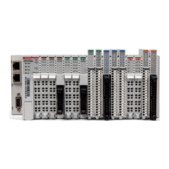
Hitachi HX-RIO3 Series User Manual
Power module
Hide thumbs
Also See for HX-RIO3 Series:
- Manual (68 pages) ,
- User manual (63 pages) ,
- User manual (63 pages)
Table of Contents
Advertisement
Quick Links
Advertisement
Table of Contents

Related Manuals for Hitachi HX-RIO3 Series


Summary of Contents for Hitachi HX-RIO3 Series
- Page 1 HX-RIO3 Series Power Module User Manual Version 1.01...
- Page 2 HX-RIO3 Series REVISION HISTORY REV. PAGE REMARKS DATE EDITOR 1.01 New Document Feb. 2021 (OPR), (PF)
-
Page 3: Table Of Contents
HX-RIO3 Series Table of Contents Important Notes ........................5 Safety Instruction ......................6 1.1.1 Symbols ........................6 1.1.2 Safety Notes ....................... 6 1.1.3 Certification ........................ 6 Power Module List ........................7 Specification ..........................8 RIO3-SHD ........................8 3.1.1 Wiring Diagram ......................8 3.1.2... - Page 4 HX-RIO3 Series 3.4.5 Example ........................23 RIO3-VDC ........................ 24 3.5.1 Wiring Diagram ......................24 3.5.2 LED Indicator ......................25 3.5.3 Status LED ....................... 25 3.5.4 Specification ......................26 3.5.5 Example ........................27 RIO3-PS ........................28 3.6.1 Wiring Diagram ......................28 3.6.2...
-
Page 5: Important Notes
In no event will HITACHI be responsible or liable for indirect or consequential damages resulting from the use or application of this equipment. -
Page 6: Safety Instruction
HX-RIO3 Series 1.1 Safety Instruction 1.1.1 Symbols Identifies information about practices or circumstances that can cause an explosion in a hazardous environment, which may lead to personal injury or death property damage, or economic loss. Identifies information that is critical for successful application and understanding of the product. -
Page 7: Power Module List
HX-RIO3 Series 2 Power Module List RIO3-Number Description ID (hex) RIO3-SHD Potential Distributor, 8 CHs, Shield, 10 RTB, ID Type 7408 RIO3-0VCD Potential Distributor, 8 CHs, 0Vdc, 10 RTB, ID Type 7508 Expansion Power, System/Field Power, Input 24Vdc, Output 5Vdc, 1A,... -
Page 8: Specification
HX-RIO3 Series 3 Specification 3.1 RIO3-SHD 3.1.1 Wiring Diagram Pin No. Signal Description Signal Description Pin No. Shield Shield Shield Shield Shield Shield Shield Shield Field Power, 24V Field Power, 24G... -
Page 9: Led Indicator
HX-RIO3 Series 3.1.2 LED Indicator LED No. LED Function / Description LED Color Status Internal Bus Status Green 3.1.3 Status LED Status To indicate The unit is operating in normal condition. Normal signal. Green (After normal initialization of G-Bus communication, this LED maintains ON status.) -
Page 10: Specification
HX-RIO3 Series 3.1.4 Specification Items Specification Technical Data UL Field Power Supply voltage: 24Vdc nominal, Class 2 Field Power Voltage 24Vdc nominal Max. 10A Operating Temperature Field Power Contacts Current -40℃ ~ 50℃: Max. 10A 50℃ ~ 70℃: Max. 7A... -
Page 11: Example
HX-RIO3 Series 3.1.5 Example RIO3-SHD Shield... -
Page 12: Rio3-0Vcd
HX-RIO3 Series 3.2 RIO3-0VCD 3.2.1 Wiring Diagram Pin No. Signal Description Signal Description Pin No. 0VDC/L2 0VDC/L2 0VDC/L2 0VDC/L2 0VDC/L2 0VDC/L2 0VDC/L2 0VDC/L2 0VDC/L2 0VDC/L2... -
Page 13: Led Indicator
HX-RIO3 Series 3.2.2 LED Indicator LED No. LED Function / Description LED Color Status Internal Bus Status Green 3.2.3 Status LED Status To indicate The unit is operating in normal condition. Normal signal. Green (After normal initialization of G-Bus communication, this LED maintains ON status.) -
Page 14: Specification
HX-RIO3 Series 3.2.4 Specification Items Specification Technical Data UL Field Power Supply voltage: 24Vdc nominal, Class 2 Field Power Voltage 24Vdc nominal Max. 10A Operating Temperature Field Power Contacts Current -40℃ ~ 50℃: Max. 10A 50℃ ~ 70℃: Max. 7A... -
Page 15: Example
HX-RIO3 Series 3.2.5 Example RIO3-0VCD Common 0Vdc... -
Page 16: Rio3-Psd
HX-RIO3 Series 3.3 RIO3-PSD 3.3.1 Wiring Diagram Pin No. Signal Description Signal Description Pin No. System Power, 24V System Power, Ground System Power, 24V System Power, Ground Frame Ground Frame Ground Field Power, Ground Field Power, Ground Field Power, 24V... -
Page 17: Led Indicator
HX-RIO3 Series 3.3.2 LED Indicator LED No. LED Function / Description LED Color System Power System Power Green Field Power Field Power Green Status Internal Bus Status Green 3.3.3 System / Field Power LED Status To indicate On Signal Green... -
Page 18: Specification
HX-RIO3 Series 3.3.5 Specification Items: RIO3-PSD Input Specification System Input Voltage range 15Vdc to 30Vdc System Power Input Voltage 24Vdc nominal Indicators 1 Green System Power status, 1 Green Field Power status, 1 Green G-Bus status UL Field Power Supply voltage: 24Vdc nominal, Class 2 Field Power Input Voltage 24Vdc (±20%) nominal... -
Page 19: Example
HX-RIO3 Series 3.3.6 Example RIO3-PSD Provides the additional Power. -
Page 20: Rio3-24Vdc
HX-RIO3 Series 3.4 RIO3-24VDC 3.4.1 Wiring Diagram Pin No. Signal Description Signal Description Pin No. 24VDC/L1 24VDC/L1 24VDC/L1 24VDC/L1 24VDC/L1 24VDC/L1 24VDC/L1 24VDC/L1 24VDC/L1 24VDC/L1... -
Page 21: Led Indicator
HX-RIO3 Series 3.4.2 LED Indicator LED No. LED Function / Description LED Color Status Internal Bus Status Green 3.4.3 Status LED Status To indicate The unit is operating in normal condition. Normal signal. Green (After normal initialization of G-Bus communication, this LED maintains ON status.) -
Page 22: Specification
HX-RIO3 Series 3.4.4 Specification Items Specification Technical Data UL Field Power Supply voltage: 24Vdc nominal, Class 2 Field Power Voltage 24Vdc nominal Max. 10A Operating Temperature Field Power Contacts Current -40℃~50℃: Max. 10A 50℃~70℃: Max. 7A Indicator 1 Green Internal Bus Status... -
Page 23: Example
HX-RIO3 Series 3.4.5 Example The RIO3-24VDC Common 24Vdc... -
Page 24: Rio3-Vdc
HX-RIO3 Series 3.5 RIO3-VDC 3.5.1 Wiring Diagram Pin No. Signal Description Signal Description Pin No. 24VDC/L1 0VDC/L2 24VDC/L1 0VDC/L2 24VDC/L1 0VDC/L2 24VDC/L1 0VDC/L2 24VDC/L1 0VDC/L2... -
Page 25: Led Indicator
HX-RIO3 Series 3.5.2 LED Indicator LED No. LED Function / Description LED Color Status Internal Bus Status Green 3.5.3 Status LED Status To indicate The unit is operating in normal condition. (After normal initialization of G-Bus communication, Normal signal Green this LED maintains ON status.) -
Page 26: Specification
HX-RIO3 Series 3.5.4 Specification Items Specification Technical Data UL Field Power Supply voltage: 24Vdc nominal, Class 2 Field Power Voltage 24Vdc nominal Max. 10A Operating Temperature Field Power Contacts Current -40℃~50℃: Max. 10A 50℃~70℃: Max. 7A Indicator 1 Green Internal Bus Status... -
Page 27: Example
HX-RIO3 Series 3.5.5 Example RIO3-VDC Common 24Vdc, 0Vdc... -
Page 28: Rio3-Ps
HX-RIO3 Series 3.6 RIO3-PS 3.6.1 Wiring Diagram Pin No. Signal Description Signal Description Pin No. Frame Ground Frame Ground Field Power, Arbitrary (N) Field Power, Arbitrary (N) Field Power, Arbitrary (P) Field Power, Arbitrary (P) -
Page 29: Led Indicator
HX-RIO3 Series 3.6.2 LED Indicator LED No. LED Function / Description LED Color Status Internal Bus Status Green 3.6.3 Status LED Status To indicate The unit is operating in normal condition. Normal signal. Green (After normal initialization of G-Bus communication, this LED maintains ON status.) -
Page 30: Specification
HX-RIO3 Series 3.6.4 Specification Items Specification Technical Data UL Field Power Supply voltage: 24Vdc nominal, Class 2 Field Power Voltage 24Vdc nominal Max. 10A Operating Temperature Field Power Contacts Current -40℃~50℃: Max. 10A 50℃~70℃: Max. 7A Indicator 1 Green Internal Bus Status... -
Page 31: Example
HX-RIO3 Series 3.6.5 Example RIO3-PS provides Field Power... -
Page 32: Environment Specification
HX-RIO3 Series 4 Environment Specification Environmental Specification Operation Temperature -40℃ ~ 70℃ UL Temperature -20℃ ~ 60℃ Non-Operating Temperature -40℃ ~ 85℃ Relative Humidity 5% ~ 90% Non-condensing Mounting DIN rail General Specification Shock Operating IEC 60068-2-27 Based on IEC 60068-2-6... -
Page 33: Dimension
HX-RIO3 Series 5 Dimension 5.1 10-Pts. Spring Type Dimensions in mm... -
Page 34: Mounting
HX-RIO3 Series 6 Mounting Caution! Hot surface! The surface of the housing can become hot during operation. If the device was operated at high ambient temperatures, allow it to cool off before touching it. Notice! Perform work on devices only if they are de-energized! Working on energized devices can damage them. -
Page 35: Rtb (Removable Terminal Block)
HX-RIO3 Series 6.2 RTB (Removable Terminal Block) Whole terminal block can be combined and removed for the convenience if its maintenance. There is a locking switch on the RTB for the easy combination and easy removal. Easy combination and easy removal for IO modules on the din rail through One Touch Locking Switch. -
Page 36: Bus Pin Description
HX-RIO3 Series 7 G-Bus Pin Description Communication between the RIO3-Series and the expansion module as well as system / field power supply of the bus modules is carried out via the internal bus. It is comprised of 6 data pin and 2 field power pin. -
Page 37: Troubleshooting
HX-RIO3 Series 8 Troubleshooting In this manual, all variety cases can’t be described. If you can’t find any fault after investigating all below cases, please refer to user manuals of G-Series Network adapters. LED Status Cause Action EXPANSION MODULE No Power Device has no expansion Module or may not be powered. -
Page 38: Appendix
HX-RIO3 Series 9 APPENDIX 9.1 Product List RIO3-Number Description ID (hex) Digital Input Module RIO3-XDP8 8 Points, Universal, 24Vdc, 10RTB 1238 RIO3-XDP16C 16 Points, Universal, 24Vdc, 20P connector 123F RIO3-XDP16T 16 Points, Universal, 24Vdc, 18RTB 12DF RIO3-XDP32C 32 Points, Universal, 24Vdc, 40P connector... -
Page 39: Glossary
HX-RIO3 Series RIO3-AYH4I 4 Channels, Current Output, 4~20mA, 16bits 4254 RIO3-AY8I 8 CHANNELS CURRENT OUTPUT, 4~20mA, 12BIT 4218 RIO3-AY4V 4CH, 0~10Vdc, 12Bits, 10RTB 4424 RIO3-AYH4V 4CH, 0~10Vdc, 16Bits, 10RTB 4464 RIO3-AY8V 8CH, 0~10Vdc, 12Bits, 10RTB 4428 RIO3-AY16VC 16CH, 0~10Vdc, 12Bits, 20P Connector...