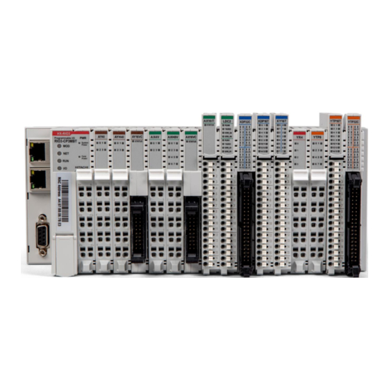
Hitachi HX-RIO3 Series User Manual
Special i/o module
Hide thumbs
Also See for HX-RIO3 Series:
- Manual (68 pages) ,
- User manual (63 pages) ,
- User manual (34 pages)
Table of Contents
Advertisement
Quick Links
Advertisement
Table of Contents

Related Manuals for Hitachi HX-RIO3 Series


Summary of Contents for Hitachi HX-RIO3 Series
- Page 1 HX-RIO3 Series Special I/O Module RIO3-CU24L User Manual Version 1.02...
- Page 2 HX-RIO3 Series DOCUMENT REVISION PAGE REMARKS DATE EDITOR 1.00 New Document Nov 2020 (OPR), (PF) 1.00 Remove product list table and add a reference Aug 2021 (PF) 1.02 Typo correction ( Jan 2022 (PF) B’ 1011 ( 0xB ), B’ 1100 ( 0xC )
-
Page 3: Table Of Contents
HX-RIO3 Series Table of Contents Important Notes ............................ 4 Safety Instruction .......................... 5 1.1.1 Symbols ........................... 5 1.1.2 Safety Notes ..........................5 1.1.3 Certification ..........................5 Specification ............................6 RIO3-CU24L..........................6 2.1.1 Wiring Diagram ......................... 6 2.1.2 LED Indicator ..........................7 2.1.3... -
Page 4: Important Notes
In no event will HITACHI be responsible or liable for indirect or consequential damages resulting from the use or application of this equipment. -
Page 5: Safety Instruction
HX-RIO3 Series 1.1 Safety Instruction 1.1.1 Symbols Identifies information about practices or circumstances that can cause an explosion in a hazardous environment, which may lead to personal injury or death property damage, or economic loss. Identifies information that is critical for successful application and understanding of the product. -
Page 6: Specification
HX-RIO3 Series 2 Specification 2.1 RIO3-CU24L 2.1.1 Wiring Diagram Pin No. Signal Description Signal Description Pin No. A Ph Input+ Ch# 0 A Ph Input- Ch# 0 B Ph Input+ Ch# 0 B Ph Input- Ch# 0 A Ph Input+ Ch# 1... -
Page 7: Led Indicator
HX-RIO3 Series 2.1.2 LED Indicator LED No. LED Function / Description LED Color Aph Input Ch# 0 Green Bph Input Ch# 0 Green Aph Input Ch# 1 Green Bph Input Ch# 1 Green 2.1.3 Channel Status LED Status LED is... -
Page 8: Specification
HX-RIO3 Series 2.1.4 Specification Items Specification Input specification Number of channels 2 channels - Encoder, High Speed Counter, Frequency measurement Pulse width & Period measurement Indicators 4 green terminal input Input voltage 24Vdc nominal (Max 28.8Vdc) Input current 3mA @ 24Vdc Min on-state voltage ≥16.5Vdc... -
Page 9: Mapping Data Into The Image Table
HX-RIO3 Series 2.1.5 Mapping data into the image table Input Image Data – 8byte Byte Bit 7 Bit 6 Bit 5 Bit 4 Bit 3 Bit 2 Bit 1 Bit 0 Counter Value Ch#0 LL Counter Value Ch#0 LH Counter Value Ch#0 HL... - Page 10 HX-RIO3 Series Count Mode Ch#0, Ch#1 Value Count Mode Description Up Counter - Aph Input acts as Up Clock B’ 0000 (0x0) - Bph Input is not used Down Counter - Aph Input acts as Down Clock Down B’ 0001 (0x1) - Bph Input is not used B’...
-
Page 11: Configuration Parameter Data - 4Byte
HX-RIO3 Series Simple Pulse Width Measurement, 0.1usec Unit Pulse Width - Pulse Width(32bit), if 1234, then Pulse High(On) width is Measurement (*3) 123.4usec (*3) B’ 1110 ( 0xE ) - Aph Input acts as Pulse Input - Bph Input is not used Simple Pulse Width &... -
Page 12: Environment Specification
HX-RIO3 Series 3 Environment Specification Environmental specification Operating Temperature -20℃ ~ 70℃ UL Temperature -20℃ ~ 60℃ Storage Temperature -40℃ ~ 85℃ Relative Humidity 5% ~ 90% non-condensing Mounting DIN rail General specification Shock Operating IEC 60068-2-27: 2008/15g, 11ms Based on IEC 60068-2-6... -
Page 13: Dimension
HX-RIO3 Series 4 Dimension 4.1 10-Pts. Spring Type Dimensions in mm... -
Page 14: Mounting
HX-RIO3 Series 5 Mounting Caution! Hot surface! The surface of the housing can become hot during operation. If the device was operated at high ambient temperatures, allow it to cool off before touching it. Notice! Perform work on devices only if they are de-energized! Working on energized devices can damage them. -
Page 15: Rtb (Removable Terminal Block)
HX-RIO3 Series 5.2 RTB (Removable Terminal Block) Whole terminal block can be combined and removed for the convenience if its maintenance. There is a locking switch on the RTB for the easy combination and easy removal. Easy combination and easy removal for IO modules on the din rail through One Touch Locking Switch. -
Page 16: Bus Pin Description
HX-RIO3 Series 6 G-Bus Pin Description Communication between the Network Adapter and the expansion module as well as system / field power supply of the bus modules is carried out via the internal bus. It is comprised of 6 data pin and 2 field power pin. -
Page 17: Product List
HX-RIO3 Series 7 APPENDIX A 7.1 Product List Please refer the separate HX-RIO3 product list document 7.2 Glossary System Power: The power for starting up CPU. Field Power: The power for input and output line. Terminator Resistor: Resistor for prevention reflected wave.