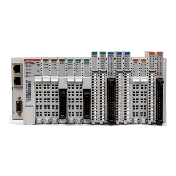
Hitachi HX-RIO3 Series User Manual
Profibus network adapter
Hide thumbs
Also See for HX-RIO3 Series:
- Manual (68 pages) ,
- User manual (63 pages) ,
- User manual (39 pages)
Table of Contents
Advertisement
Quick Links
Advertisement
Table of Contents

Related Manuals for Hitachi HX-RIO3 Series


Summary of Contents for Hitachi HX-RIO3 Series
- Page 1 HX-RIO3 Series PROFIBUS Network Adapter RIO3-PBA User Manual...
- Page 2 HX-RIO3 Series DOCUMENT CHANGE SUMMARY PAGE REMARKS DATE EDITOR 1.01 March 21 Faber...
-
Page 3: Table Of Contents
HX-RIO3 Series Content 1. Important Notes ............................5 1.1.1. Symbols ..............................6 1.1.2. Safety Notes ............................6 1.1.3. Certification ............................6 2. Environment Specification ......................... 7 3. RIO3-PBA (PROFIBUS Network Adapter) ....................8 3.1. RIO3-PBA Specification ........................... 8 3.2. RIO3-PBA Wiring Diagram ........................10 3.3. - Page 4 HX-RIO3 Series 7.1. RIO3-PBA ..............................25 8. DPV1 Service .............................. 25 8.1. MSAC1 Read(PROFIBUS-DP Extensions to EN50170) ............... 25 8.2. MSAC1 Write (PROFIBUS-DP Extensions to EN50170) ..............26 8.3. Error Decode (PROFIBUS-DP Extensions to EN50170) ..............27 8.4. Error_Code_1 (PROFIBUS-DP Extensions to EN50170) ..............27 8.5.
-
Page 5: Important Notes
In no event will HITACHI be responsible or liable for indirect or consequential damages resulting from the use or application of this equipment. The examples and diagrams in this manual are included solely for illustrative purposes. -
Page 6: Symbols
HX-RIO3 Series 1.1.1. Symbols Identifies information about practices or circumstances that can cause an explosion in a hazardous environment, which may lead to personal injury or death property damage or economic loss. Identifies information that is critical for successful application and understanding of the product. -
Page 7: Environment Specification
HX-RIO3 Series 2. Environment Specification Environment Specification Operating Temperature 60℃ ~ 70℃ : Power dissipation is limited to 0.8A -40℃ ~ 60℃ : 1.5A full load is allowed UL Temperature -20℃~60℃ Storage Temperature -40℃~85℃ Relative Humidity 5% ~ 90% non-condensing... -
Page 8: Rio3-Pba (Profibus Network Adapter)
8 (Fixed) Parity bit : No parity (Fixed) Stop bit 1 (Fixed) Module Location Starter module left side of HX-RIO3 Series System Field Power Detection About 14Vdc General Specification UL System Power Supply voltage : 24Vdc Nominal, Class 2 Supply voltage : 24Vdc nominal... - Page 9 HX-RIO3 Series Field Power range is different depending on IO module series. Refer to IO module’s specification. Max. Current Field Power Contact DC 10A Max. Wiring I/O Cable Max. 2.0mm²(AWG 14) Torque 0.8Nm(7 lb-in) Weight 163g Module Size 54mm x 99mm x 70mm Refer to ‘Environment Specification’...
-
Page 10: Rio3-Pba Wiring Diagram
HX-RIO3 Series 3.2. RIO3-PBA Wiring Diagram Pin No. Signal Description Signal Description Pin No. System Power, 24V System Power, Ground System Power, 24V System Power, Ground Field Power, Ground Field Power, Ground Field Power, 24V Field Power, 24V... -
Page 11: Rio3-Pba Led Indicator
HX-RIO3 Series 3.3. RIO3-PBA LED Indicator 3.3.1. LED Indicator LED No. LED Function / Description Colour Module Status Green/Red Network Status Green/Red Diagnostic Status Extension Module Status Green/Red System Power System Power Enable Green Field Power Field Power Enable Green 3.3.2. -
Page 12: Dia (Diagnostic Status Led)
HX-RIO3 Series 3.3.4. DIA (Diagnostic Status LED) Status To indicate : Device has hardware checking error. Hardware Error Flashing Red (with MOD led is red.) Device has expansion module error. Expansion Module Error Flashing Red (with IOS led is red.) Failed to initialize expansion module - Overflow Input/Output size. -
Page 13: Rio3-Pba Electrical Interface
HX-RIO3 Series 3.4. RIO3-PBA Electrical Interface 3.4.1. PROFIBUS Connector Pin No. Description RxD / TxD-P CNTR-P DGND RXD / TxdD-N 3.4.2. Dip Switch Terminating Resistance Applied Not applied Node ID... -
Page 14: Rs232 Port For Modbus/Rtu, Touch Panel Or Ioguide
An expansion module may have 3 types of data as I/O data, configuration parameter and memory register. The data exchange between network adapter and expansion modules is done via an I/O process image data by HX-RIO3 Series Internal Bus protocol. The following figure shows the data flow of process image between network adapter and expansion modules. -
Page 15: Example Of Input Process Image (Input Register) Map
HX-RIO3 Series 3.5.1. Example of Input Process Image (Input Register) Map Input image data depends on slot position and expansion slot data type. Input process image data is only ordered by expansion slot position. • Example slot configuration Slot Address... -
Page 16: Example Of Output Process Image (Output Register) Map
HX-RIO3 Series 3.5.2. Example of Output Process Image (Output Register) Map Output image data depends on slot position and expansion slot data type. Output process image data is only ordered by expansion slot position. • Example slot configuration Slot Module Description... -
Page 17: Dimension
HX-RIO3 Series 4. Dimension 4.1. RIO3-PBA (mm) -
Page 18: Mechanical Set Up
HX-RIO3 Series 5. Mechanical Set Up 5.1. Total Expansion The number of the module assembly that can be connected is 63. The maximum length is 426mm Exception. 5.2. Plugging and Removal of the Components. As above figure to safeguard the RIO3 module from jamming, it should be fixed onto the DIN rail with locking level. -
Page 19: G-Bus Pin Description
HX-RIO3 Series 5.3. G-Bus Pin Description Communication between the RIO3 series and the expansion module as well as system / field power supply of the bus modules is carried out via the internal bus. It is comprised of 6 data pin and 2 field power pins. -
Page 20: Profibus Electrical Interface
HX-RIO3 Series 6.PROFIBUS Electrical Interface 6.1. G-Bus System • Network Adapter Module The Network Adapter Module forms the link between the field bus and the field devices with the Expansion Modules. The connection to different field bus systems can be established by each of the corresponding Network Adapter Module, e.g. -
Page 21: Profibus Electrical Interface
HX-RIO3 Series 6.2. PROFIBUS Electrical Interface 6.2.1. RIO3-PBA Dsub 9 Signal Description (Female) Name RXD/TXD-P Receive/Transmit data-plus(B wire) Repeater control signal(direction control), CNTR-P RTS signal DGND Data ground(reference potential for VP) Supply voltage-Plus(P5V) RXD/TXD-N Receive/Transmit data-minus(A-wire) CNTR-N Repeater Control Signal(direction control) All fieldbus devices which use a standard 9-pin Sub-D connector should provide the VP and DGND signals on the bus connector in addition to the receive and transmit signals. -
Page 22: Terminator Resistor
HX-RIO3 Series 6.2.2. Terminator Resistor To minimize cable reflections and ensure a defined noise level on the data lines, the data transfer cable must be terminated at both ends with a terminating resister combination as follows. -
Page 23: Profibus Address Setup
HX-RIO3 Series 6.2.3. PROFIBUS Address Setup Each PROFIBUS Adapter could have a unique address (from 1 to 99) so that it can be addressed independently from other nodes. The address 0 is reserved to identify a broadcast exchange. No response is returned to broadcast requests sent by the master. -
Page 24: Choice Of Profibus Data Transfer Cable Type
HX-RIO3 Series 6.2.4. Choice of PROFIBUS data transfer cable type Depending on the application, the user can choose between electrical and optical fibre data transfer cables. The following types of electrical data cables can be used: - Standard bus cable - Standard bus cable with halogen-free sheath (type FRNC) - Cable with PE Sheath for use in the food and manufacturing industries. -
Page 25: Parameter
HX-RIO3 Series 7. Parameter 7.1. RIO3-PBA • Parameter length: 3 bytes • Parameter Data: Offset Access Decimal Bit Description Default Value 00-01 Word Data Format 1 (Motorola) 0 : Little-Endian (INTEL) 1 : Big-Endian (MOTOROLA) 02-07 Reserved 00-04 Reserved PROFIBUS Disconnection... -
Page 26: Msac1 Write (Profibus-Dp Extensions To En50170)
HX-RIO3 Series 8.2. MSAC1 Write (PROFIBUS-DP Extensions to EN50170) MSAC1 Write Request Parameter Description Remote Address Slave Address (0~99) Slot Number Slot Number : 0(RIO3-PBA) Index 254 : Vendor code (Data size : 5 bytes) Length 1~128 Vendor (Don’t mention this to the User manual) -
Page 27: Error Decode (Profibus-Dp Extensions To En50170)
HX-RIO3 Series 8.3. Error Decode (PROFIBUS-DP Extensions to EN50170) ▶ 0~127 : Reserved ▶ 128 : DPV1 ▶ 129~253 : Reserved ▶ 254 : FMS ▶ 255 : HART 8.4. Error_Code_1 (PROFIBUS-DP Extensions to EN50170) Error Class Error code 0xA : Application class... -
Page 28: Diagnostics
HX-RIO3 Series 8.5. Diagnostics Byte Item Description Station status 1 Station status 2 PROFIBUS Standard Station status 3 Diagnostic Master Address PNO Ident Number High PNO Ident Number Low • Station Status 1~3 Station status Bit 7 Master_Lock Slave is parameterized by another master... -
Page 29: Modbus Interface
HX-RIO3 Series 9. MODBUS Interface 9.1. MODBUS Interface Register/Bit Map • Register Map Start Address Read/Write Description Func. Code 0x0000 ~ Read Process input image registers (Real Input Register) 3,4,23 0x0800 ~ Read/Write Process output image registers (Real Output Register) - Page 30 HX-RIO3 Series 3(0x03) Read Holding This function code is used to read the contents of a contiguous block of Registers holding registers in a remote device. The Request PDU specifies the (Read output starting register address and the number of registers. The register data in...
-
Page 31: 0X08) Diagnostics
HX-RIO3 Series 9.2.1. 8(0x08) Diagnostics Sub-function 0x0000(0) Return Query Data The data passed in the request data field is to be returned (looped back) in the response. The entire response message should be identical to the request. Sub-function Data Field (Request) -
Page 32: Error Response
HX-RIO3 Series Sub-function Data Field (Request) Data Field (Response) Description 0x000F(15) 0x0000 Slave No Response Count Sub-function 0x0064(100) Return Slave ModBus, Expansion Module Status The response data field returns the status of ModBus and expansion module addressed to the remote device. -
Page 33: Modbus Special Register Map
(one address). 9.3.1. Adapter Identification Special Register (0x1000, 4096) Address Access Type, Size Description 0x1000(4096) Read 1word Vendor ID = 0x029D(669), HITACHI 0x1001(4097) Read 1word Device type = 0x000C, Network Adapter 0x1002(4098) Read 1word Product Code = 0x9040... -
Page 34: Adapter Information Special Register (0X1100, 4352)
0x111D(4381) Read 1word Adapter HX-RIO3 Series Revision. If 0x013C, HX-RIO3 Series Revision is 1.60 * ** After the system is reset, the new “Set Value” action is applied. ** If the slot location is changed, set default value automatically (all expansion slot is live). - Page 35 HX-RIO3 Series …… Address Expansion Expansion Expansion Expansion Expansion Offset Slot#1 Slot#2 Slot#3 Slot#4 Slot#63 …… + 0x00(+0) 0x2000(8192) 0x2020(8224) 0x2040(8256) 0x2060(8288) 0x27C0(10176) + 0x01(+1) 0x2001(8193) 0x2021(8225) 0x2041(8257) 0x2061(8289) 0x27C1(10177) + 0x02(+2) 0x2002(8194) 0x2022(8226) 0x2042(8258) 0x2062(8290) 0x27C2(10178) + 0x03(+3) 0x2003(8195)
- Page 36 HX-RIO3 Series + 0x0B(+11) ** Read/Write n word Read/write output data this slot + 0x0E(+14) Read 1word RT-number, if RT-1238, returns 0x1238 + 0x0F(+15) Read String First 1word is length of valid character string. up to If RT-1238, returns “00 1E 52 54 2D 31 32 33 38 2C 20 38 44 49 2C 20 32 34 56 64 63 74byte 2C 20 55 6E 69 76 65 72 73 61 6C 00 00”...
-
Page 37: Troubleshooting
HX-RIO3 Series 10. Troubleshooting 10.1. How to diagnose by LED indicator LED Status Cause Action All LED turns off - No power Check main power Cable - Contact Sales team and send MOD LED is red - Occurrence critical error in firmware module for repair. -
Page 38: How To Diagnose When Device Couldn't Communicate Network
HX-RIO3 Series 10.2. How to diagnose when device couldn't communicate network Inspection of wrong or omission cable connection. - Check status of cable connection for each node. - Check that all colour matches between connector and cable. - Check wire omission. -
Page 39: Product List
HX-RIO3 Series APPENDIX A A.1. Product List RIO3-Number Description ID (hex) Digital Input Module RIO3-XDP8 8 Points, Universal, 24Vdc, 10RTB 1238 RIO3-XDP16C 16 Points, Universal, 24Vdc, 20P connector 123F RIO3-XDP16T 16 Points, Universal, 24Vdc, 18RTB 12DF RIO3-XDP32C 32 Points, Universal, 24Vdc, 40P connector... -
Page 40: Glossary
HX-RIO3 Series RIO3-AYH4V 4CH, 0~10Vdc, 16Bits, 10RTB 4464 RIO3-AY8V 8CH, 0~10Vdc, 12Bits, 10RTB 4428 RIO3-AY16VC 16CH, 0~10Vdc, 12Bits, 20P Connector 442F RIO3-AY16VT 16CH, 0~10Vdc, 12Bits, 18RTB 447F Special Module RIO3-CU24L High Speed Counter, 2CHs, 24Vdc, Encoder Input, 10RTB RIO3-RS232 1CH, RS 232, RTS/CTS, Full Duplex Type, 10RTB...