Table of Contents
Advertisement
Quick Links
Advertisement
Table of Contents

Related Manuals for HIKVISION DS-K1108 Series


Summary of Contents for HIKVISION DS-K1108 Series
- Page 1 DS-K1108 Series Card Reader User Manual UD01841B...
- Page 2 ALL RIGHTS RESERVED. Any and all information, including, among others, wordings, pictures, graphs are the properties of Hangzhou Hikvision Digital Technology Co., Ltd. or its subsidiaries (hereinafter referred to be “Hikvision”). This user manual (hereinafter referred to be “the Manual”) cannot be reproduced, changed, translated, or distributed, partially or wholly, by any means, without the prior written permission of Hikvision.
- Page 3 DAMAGES, INCLUDING, AMONG OTHERS, DAMAGES FOR LOSS OF BUSINESS PROFITS, BUSINESS INTERRUPTION, OR LOSS OF DATA OR DOCUMENTATION, IN CONNECTION WITH THE USE OF THIS PRODUCT, EVEN IF HIKVISION HAS BEEN ADVISED OF THE POSSIBILITY OF SUCH DAMAGES. REGARDING TO THE PRODUCT WITH INTERNET ACCESS, THE USE OF PRODUCT SHALL BE WHOLLY AT YOUR OWN RISKS.
-
Page 4: Table Of Contents
Content CHAPTER 1 PREVENTIVE AND CAUTIONARY TIPS ....2 CHAPTER 2 INTRODUCTION ..........3 ............3 RONT .............. 4 CHAPTER 3 INSTALLATION ..........4 PSAM C ..........4 NSTALLING DIP S ......... 5 NTRODUCTION FOR WITCH ..........6 EFINITION OF ABLE ............ -
Page 5: Chapter 1 Preventive And Cautionary Tips
Chapter 1 Preventive and Cautionary Tips To guarantee the card reader works properly, please read and obey the notes below. If the card reader is powered by the controller, the power supply distance is recommended to be no longer than 100m. If the distance is longer than 100m, you are advised to power the card reader by external 12V (range: -%10 ~ +%10) DC power supply, which is nonswitched and linear. -
Page 6: Chapter 2 Introduction
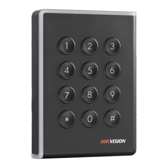
Chapter 2 Introduction DS-K1108 series card reader is a kind of high-performance product, with a 32 bit high-speed processor. It communicates with access controller via either RS-485 protocol or Wiegand protocol. And a build-in tamper-proof module helps to protect card reader from malicious damage. -
Page 7: Rear View
2.2 Rear View Figure 2-2 Rear View of DS-K1108 Series Chapter 3 Installation 3.1 Installing PSAM Card PSAM card slot is only available for CPU card reader. Insert the PSAM card into the slot according to the direction shown below. -
Page 8: Introduction For Dip Switch
Figure 3-1 PSAM Card Slot 3.2 Introduction for DIP Switch The DIP switch module is shown below. The No. of DIP switch from left to right is 1 ~ 8. Figure 3-2 DIP Switch Module Table 3-1 Description of DIP Switch Icon Description Represent 1 in binary mode... -
Page 9: Definition Of Cable
Description DIP Switch Status (Only available for CPU card 0: read file in card. reader.) Wiegand protocol or RS-485 1: Wiegand protocol; protocol. 0: RS-485 protocol. 1: Wiegand protocol Wiegand Protocol of 26-bit; (available when No. 6 is 1) 0: Wiegand protocol of 34-bit. -
Page 10: Wiring Cables
3.4 Wiring Cables Purpose: Wire the cables between controller and card reader, thus to establish the communication between them. Steps for RS-485 communication mode: Set the DIP switch of No. 6 as 0. Set the DIP switch of No. 1 ~ 5 for RS-485 address and reading card mode. - Page 11 Set the DIP switch of No. 6 as 1. Set the DIP switch of No. 5 and 7 for reading card mode and Wiegand protocol. For details, please refer to 3.2 Introduction for DIP Switch. Wiring the cable between controller and card reader as shown below.
-
Page 12: Chapter 4 Sound Prompt And Indicator
Chapter 4 Sound Prompt and Indicator After the card reader is powered on, LED status indicator will turn green and blink for 1 time. Then it will turn red and blink for 3 times. At last the buzzer will send out a beep sound indicating the starting up process is completed. - Page 13 LED Indicator Status Description time), and red (blink for 3 times) For Card + Password authentication: Green and blinking prompt for entering the password after swiping the card. The operation of pressing keys or swiping Solid green for 2s card is valid. Solid red Card reader is working normally.