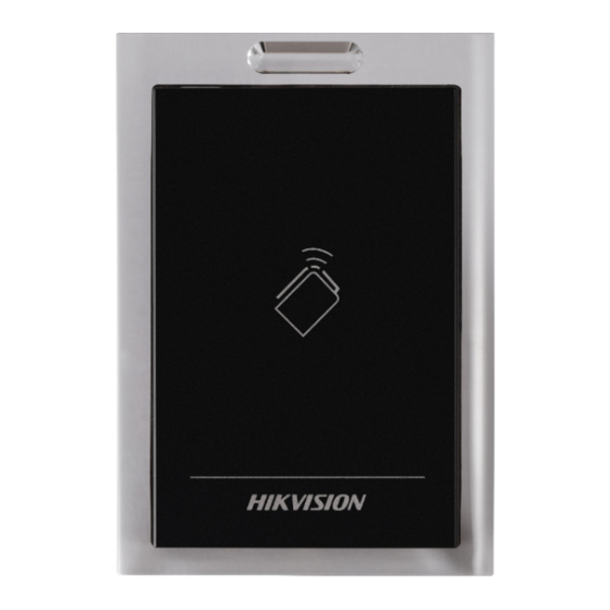
HIKVISION DS-K1101M Installation Manual
Ds-k1100 series
Hide thumbs
Also See for DS-K1101M:
- Installation manual (16 pages) ,
- User manual (24 pages) ,
- Quick start manual (5 pages)
Advertisement
Advertisement
Table of Contents

Summary of Contents for HIKVISION DS-K1101M
- Page 1 DS-K1100 Series Card Reader Installation Manual UD.6L0206A1004A01...
- Page 2 Regulatory information FCC information This device complies with Part 15 of the FCC Rules. Operation is subject to the following two conditions: (1) This device may not cause harmful interference. (2) This device must accept any interference received, including interference that may cause undesired operation. Please take attention that changes or modification not expressly approved by the party responsible for compliance could void the user’s authority to operate the equipment.
- Page 3 Thank you for purchasing our product. If there is any question or request, please do not hesitate to contact the dealer. This manual is applicable to the following models: Series Models Description DS-K1101M MIFARE card reader (without keypad) DS-K1101 DS-K1101MK MIFARE card reader (with a keypad) Series...
-
Page 4: Chapter 1 Preventive And Cautionary Tips
Chapter 1 Preventive and Cautionary Tips To guarantee the card reader works properly, please read and obey the notes below. If the card reader is powered by the controller, the power supply distance is recommended to be no longer than 100m. If the distance is longer than 100m, you are advised to power the card reader by external 12V (range: -%10 ~ +%10) DC power supply, which is nonswitched and linear. -
Page 5: Front View
2.1 Front View The front view of DS-K1101 series card reader is shown below: Figure 2-1 DS-K1101MK/DS-K1101CK Figure 2-2 DS-K1101M/DS-K1101C The front view of DS-K1102 series card reader is shown below: Figure 2-3 DS-K1102MK/DS-K1102CK Figure 2-4 DS-K1102M/DS-K1102C... -
Page 6: Rear View
The front view of DS-K1103 series card reader is shown below: Figure 2-5 DS-K1103MK/DS-K1103CK Figure 2-6 DS-K1103M/DS-K1103C The front view of DS-K1104 series card reader is shown below: Figure 2-7 DS-K1104MK/DS-K1104CK Figure 2-8 DS-K1104M/DS-K1104C 2.2 Rear View The rear view of card reader is shown below:... - Page 7 Figure 2-9 Rear View of DS-K1101 Series Figure 2-10 Rear View of DS-K1102 Series...
- Page 8 Figure 2-11 Rear View of DS-K1103 Series Figure 2-12 Rear View of DS-K1104 Series...
-
Page 9: Side View
Table 2-1 Description of Rear View Name Cable Interface of RS-485, Power, LED Control, etc. Buzzer Tamper-proof Module DIP Switch PSAM Card Slot (available for CPU card reader) 2.3 Side View The side view of card reader is shown below: Figure 2-13 DS-K1101 Series Figure 2-14 DS-K1102 Series... -
Page 10: Chapter 3 Installation
Figure 2-15 DS-K1103 Series Figure 2-16 DS-K1104 Series Chapter 3 Installation 3.1 Installing PSAM Card PSAM card slot is only available for CPU card reader. Insert the PSAM card into the slot according to the direction shown below. Figure 3-1 PSAM Card Slot... -
Page 11: Introduction For Dip Switch
3.2 Introduction for DIP Switch The DIP switch module is shown below. The No. of DIP switch from left to right is 1 ~ 8. Figure 3-2 DIP Switch Module Table 3-1 Description of DIP Switch Icon Description Represent 1 in binary mode Represent 0 in binary mode For example, binary value of the following status is: 0000 1100. -
Page 12: Definition Of Cable
Description DIP Switch Status 1: Wiegand protocol Wiegand Protocol of 26-bit; (available when No. 6 is 1) 0: Wiegand protocol of 34-bit. Matched Resistance 1: Enable; (available for RS-485 protocol) 0: Disable. 3.3 Definition of Cable The description of 10 cables is shown below. Table 3-3 Description of Cable Color Description... - Page 13 Set the DIP switch of No. 6 as 0. Set the DIP switch of No. 1 ~ 5 for RS-485 address and reading card mode. For details, please refer to 3.2 Introduction for DIP Switch. Wire the cable between controller and card reader as shown below.
-
Page 14: Installing Card Reader
Wiring the cable between controller and card reader as shown below. Figure 3-5 Wiring for Wiegand Communication Mode 3.5 Installing Card Reader Before you start: Set the DIP switch. For details, refer to 3.2 Introduction for DIP Switch. Steps:... -
Page 15: Chapter 4 Sound Prompt And Indicator
Fix the plate on the wall or other place. Connect the cables between controller and card reader. For details, refer to 3.4 Wiring Cables. Push the card reader to match the fixed plate. Fasten the screw to keep the components together. Chapter 4 Sound Prompt and Indicator After the card reader is powered on, LED status indicator will turn blue and blink for 1 time. - Page 16 Table 4-1 Description of Prompt Sound Sound Prompt Description RS-485 protocol: Pressing keys prompt; Swiping card prompt; Time out prompt for One beep pressing keys or swiping card. Wiegand protocol: Pressing keys prompt; Swiping card prompt. The operation of pressing keys or swiping Two rapid beeps card is valid.


