Table of Contents
Advertisement
Quick Links
Geometric Correction Box
Geometric Correction Box
YA-S10
YA-S10
この装置は、 クラスB情
報技術装置です。 この装
置は、 家庭環境で使用す
ることを目的としてい
ますが、 この装置がラジ
オやテレビジョン受信
機に近接して使用され
ると、 受信障害を引き起
こすことがあります。 取
扱説明書に従って正し
い取り扱いをしてくだ
さい。 VCCI-B
この装置は、 高調波電流
規格JIS C 61000-3-2
に適合しています。
この説明書は、お読みになった後も大切に保管してください。
日本語
本書の最新版は下記ウェブサイトに公開されております。
http://world.casio.com/manual/projector/
セットアップガイド
Be sure to keep all user documentation handy for future reference.
English
To obtain the latest version of this manual visit the website at the URL
below.
Setup Guide
http://world.casio.com/manual/projector/
Bitte bewahren Sie die gesamte Benutzerdokumentation für späteres
Deutsch
Nachschlagen auf.
Für die neueste Ausgabe dieser Bedienungsanleitung besuchen Sie
Setup-Anleitung
bitte unsere Website unter folgender URL.
http://world.casio.com/manual/projector/
Conservez la documentation à portée de main pour toute référence
Français
future.
Pour obtenir la toute dernière version de ce manuel, consultez le site à
Guide d'installation
l'adresse suivante.
http://world.casio.com/manual/projector/
Asegúrese de tener a mano toda la documentación del usuario para
Español
futuras consultas.
Para obtener la versión más reciente de este manual, visite nuestro
Guía de configuración
sitio web en la siguiente URL.
http://world.casio.com/manual/projector/
Conservare l'intera documentazione dell'utente a portata di mano per
Italiano
riferimenti futuri.
Per ottenere la versione più aggiornata di questo manuale, visitare il
Guida di setup
sito web all'URL riportato di seguito.
http://world.casio.com/manual/projector/
Förvara all användardokumentation nära till hands för framtida referens.
Svenska
Den senaste versionen av detta instruktionshäfte kan hämtas från
webbplatsen med följande URL-adress.
Installationshandbok
http://world.casio.com/manual/projector/
Certifique-se de guardar toda a documentação do usuário à mão para
Português
futuras referências.
Para obter a última versão deste manual, visite o site no endereço URL
Guia de Configuração
abaixo.
http://world.casio.com/manual/projector/
Bewaar alle documentatie op een veilige plaats voor latere naslag.
Nederlands
Bezoek de website op de onderstaande URL voor de nieuwste versie
van deze handleiding.
Instelgids
http://world.casio.com/manual/projector/
Muista pitää kaikki käyttöä koskevat asiakirjat lähettyvillä tulevaa
Suomi
tarvetta varten.
Saat uusimman version tästä oppaasta seuraavasta Internet-
Asetusopas
osoitteesta:
http://world.casio.com/manual/projector/
Pass på å oppbevare all brukerdokumentasjon lett tilgjenglig for
Norsk
fremtidig bruk.
For å få den nyeste utgaven av denne bruksanvisningen, besøk
Oppsettguide
nettsiden ved bruk av URL'en nedenfor.
http://world.casio.com/manual/projector/
CkJEGFSISwRPoTrDPlFiCzNrChK
Advertisement
Table of Contents

Related Manuals for Casio Touchboards YA-S10

Summary of Contents for Casio Touchboards YA-S10
- Page 1 Geometric Correction Box Geometric Correction Box YA-S10 YA-S10 この説明書は、お読みになった後も大切に保管してください。 日本語 本書の最新版は下記ウェブサイトに公開されております。 http://world.casio.com/manual/projector/ セットアップガイド Be sure to keep all user documentation handy for future reference. English To obtain the latest version of this manual visit the website at the URL below. Setup Guide http://world.casio.com/manual/projector/...
-
Page 2: Table Of Contents
XJ-SK600 Dual Projection System XJ-SK650 Dual Projection System The projector systems made up of the YA-S10 Geometric Correction Box connected to one or two separately available CASIO projectors NOTE Some models covered by this manual may not be available in certain geographic areas. - Page 3 CASIO COMPUTER CO., LTD. shall not be held liable for any loss or lost profits due to loss of data caused by malfunction or maintenance of this product, or due to any other reason.
-
Page 4: Safety Precautions
Safety Precautions Thank you for selecting this CASIO product. Be sure to read these “Safety Precautions” before trying to use it. After reading this User’s Guide, keep it in a safe place for future reference. About safety symbols Various symbols are used in this User’s Guide and on the product itself to ensure safe use, and to protect you and others against the risk of injury and against material damage. - Page 5 Unplug the Projector System. bending. Contact your original dealer or authorized • Do not twist the power cord or pull on it. CASIO service center. " Never touch the power cord or plug while ● Malfunction your hands are wet.
- Page 6 CASIO. • Never twist or pull on the power cord. • Should the electrical cord or plug Be sure to leave all internal inspection, adjustment,...
- Page 7 • Before moving the Projector System, be sure to adjustment, and repair up to your original turn it off and unplug it from the power outlet dealer or authorized CASIO service first. center. ● AC adapter Never allow the remote controller to become wet.
- Page 8 Safety Precautions Battery Precautions Disposing of the Projector System Danger Caution Should liquid leaking from an alkaline Whenever disposing of any of the part or the entire battery get into the eyes, immediately take Projector System, be sure to do so in accordance the following steps.
-
Page 9: Operating Precautions
Operating Precautions Do not look directly into the light emitted from a projector. Should you ever notice a component has dropped out of the Projector System, immediately stop using it and contact your original retailer or the contact specified for repair. For information about projector maintenance, see the projector user’s guide. - Page 10 Operating Precautions Warranty Conditions Even if your Projector System is still within the warranty period, you will be charged for repair if a problem is due to running the System non-stop for very long periods (like 24 hours), if there are any objects within 30cm (11.8 inches) of the cabinet while the System is running.
-
Page 11: Ya-S10 Overview
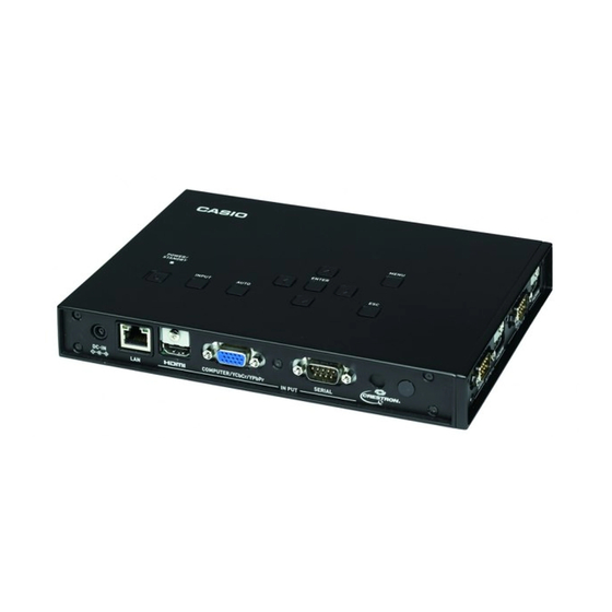
YA-S10 Overview The YA-S10 Control Box is a projector controller. Some of its major features and functions are described below. Image Shaping A variety of different functions are provided to let you shape the projected image to suit the target projection surface. -
Page 12: Getting Ready
XJ-SK600 Setup Guide or the XJ-SK650 Setup Guide. Supported Projectors You can connect one or two of the CASIO projector models below to the Control Box. XJ-M140, XJ-M145, XJ-M150, XJ-M155, XJ-M240, XJ-M245, XJ-M250, XJ-M255 XJ-H1600, XJ-H1650, XJ-H1700, XJ-H1750, XJ-H2600, XJ-H2650, XJ-ST145, XJ-ST155... -
Page 13: Wiring
Getting Ready Wiring The terminals on the sides and back of the Control Box connect to the power source and various devices as described below. Control Box Side: Connect one or two projectors. When connecting the Control Box to a projector using a supplied HDMI cable, connect the plug of the cable that is nearest the ferrite core to the HDMI port of the Control Box. -
Page 14: Preparing The Remote Controllers
Getting Ready Preparing the Remote Controllers Load the two provided AAA-size batteries into the remote controller (YT-200). To load batteries: Open the battery cover on the back of a remote controller. Load the batteries making sure their poles (+/–) are facing in the correct directions. Finally, replace the battery cover. Important! Important! Important! -
Page 15: Configuring Initial Control Box Settings
Getting Ready On the remote controller, press the [MENU] key to display the setup menu, and then configure the settings below in the indicated sequence. Setting Item Setting (1) Option Settings1 3 Auto Keystone Correction (2) Screen Settings 3 Keystone Correction (3) Screen Settings 3 No Signal Screen Black (4) Input Settings 3 Signal Name Indicator... -
Page 16: Adjusting The Position Of The Projector(S
Getting Ready Adjusting the Position of the Projector(s) Adjust the angle of the projector and the size of the projected image so the projected image is just running off the edges of the target screen (the screen or wall surface to be projected upon after Projector System setup is complete). - Page 17 Getting Ready With both the Projector A and Projector B images being projected, repeat steps 3 and 5 as required to minimize the difference between the shape of the Projector A and Projector B images. Adjustment 2: Fine adjustment using the adjustment pattern Before adjustment After adjustment On the remote controller, press the [CORRECT] key.
- Page 18 Getting Ready Press the remote controller’s [BLANK] key. This will project from Projector B again so the adjustment patterns of both Projector A and Projector B are being projected. Perform the steps below to get the adjustment pattern of Projector B as closely aligned as possible with the Projector A adjustment pattern.
-
Page 19: Shaping The Image To Match The Projection Screen
Getting Ready Next, perform the procedure under “Shaping the Image to Match the Projection Screen” (page E-18). Important! Important! Important! During the adjustment procedures from this point onwards, do not alter the position of the projector(s) or the screen, and do not change a projector zoom or focus setting. If any one of these is altered, return to step 2 of the procedure and perform the other steps again. - Page 20 Getting Ready To shape the image to match the projection screen (two projectors) NOTE After you finish the procedure under “To adjust the position of the projector (two projectors)” (page E-15), perform the procedure below. For information about which projector is Projector A and which one is Projector B, see “Wiring” (page E-12).
- Page 21 Getting Ready On the “Image Shaping” menu, select “Corner Correction” and then press the [ENTER] key. As shown in the screenshots below, both Projector A and Projector B will project grids and positioning marks. The yellow grid and mark is the Projector A image, while the light blue grid and mark is the Projector B image.
- Page 22 Getting Ready After Projector B image alignment is the way you want, press the [A ⇔ B] key. This will cause the light blue Projector B image shaping cursors to disappear and be replaced by yellow Projector A image shaping cursors. (10) Repeat steps (2) through (9) (toggling the movement speed between slow and fast with the [CORRECT] key) as many times as required to fine tune the adjustment.
- Page 23 Getting Ready Changing Only the Menu Display Mode If you want to display only the menu display mode that you selected in step 6 of the procedure under “To shape the image to match the projection screen”, press the [CORRECT] key to display the “Image Shaping”...
- Page 24 Getting Ready After the upper left corner of the projector image is where you want it, press the [POSITION] key. This will cause the shaping cursors to start flashing, which indicates that shifting of the cursors to a different location is enabled. Use the [ ] key to move the flashing shaping cursor to the upper right corner of the projector image, and then press the [CORRECT] key.
-
Page 25: Using Shaping Functions
Using Shaping Functions This section provides details about operations you need to perform when selecting one of the shaping types explained under “Shaping Types” (page E-18). Important! Important! Important! All of the operations in this section assume that the procedures under “Adjusting the Position of the Projector(s)”... -
Page 26: Shaping Type: Cylinder 1 Or Cylinder 2
Using Shaping Functions Shaping Type: Cylinder 1 or Cylinder 2 These shaping types are best for correcting for distortion that occurs when projecting onto cylindrical columns and other curved surfaces. Use “Cylinder 1” for vertical cylinders and “Cylinder 2” for horizontal cylinders. -
Page 27: Shaping Type: Free Style
Using Shaping Functions Shaping Type: Free Style This shaping type displays a 9 × 9 grid on the projection screen. You can shape the image by moving the intersects of the grid lines (up to 81 points) up, down, left, or right. Use this shaping type when projecting onto a surface that has smooth irregularities. -
Page 28: Performing Detailed Correction
Using Shaping Functions Performing Detailed Correction This section provides details about the various types of corrections that can be applied with the “Image Shaping” menu. Starting a correction operation causes a grid to appear on the projected image. The operations in the table below can be performed while a grid is displayed. To do this: Perform this operation: Move the shaping cursor to a point or line... - Page 29 Using Shaping Functions Side Correction (Arch) Use it for this: To reduce projected image distortion that occurs when projecting into a surface that shaped like a convex or concave lens. How it works: Points in the center of the top and bottom sides can be concurrently moved vertically, and points in the center of the left and right sides can be concurrently moved horizontally.
- Page 30 Using Shaping Functions Point Correction Use it for this: To reduce projected image distortion that occurs when projecting into a surface that has a smoothly irregular shape, like that or a convex or concave lens, etc. How it works: 4-Point Correction is the same as Corner Correction. It is recommended that you first perform 4-Point Correction to align the four corners of the projected image with the target screen, and then perform the other types of correction in ascending order...
-
Page 31: Adjusting The Aspect Ratio Of The Projected Image
Adjusting the Aspect Ratio of the Projected Image After performing a shaping operation, you can also adjust the aspect ratio of the projected image. Note that this operation does not adjust the aspect ratio of the input source image (which determines how the input source image fits within the projection area), but rather the aspect ratio of the image being projected. -
Page 32: Normal Operation After Getting Ready
Normal Operation after Getting Ready After you finish the procedure under “Getting Ready” (page E-11), you will be able to use the projector system (Control Box plus one or two projectors) as if it were a single projector. Perform the procedures in this section using the Control Box remote controller. -
Page 33: Product Specifications
This Software is open source code. Anyone who wishes to view the open source code can do so by downloading it from the CASIO Projector download site. Whenever copying, modifying, or distributing This Software, be sure to do so in accordance with the terms and conditions of the GPL and LGPL. - Page 34 Proper connectors must be used for connection to host computer and/or peripherals in order to meet FCC emission limits. Declaration of Conformity Model Number: YA-S10 Trade Name: CASIO COMPUTER CO., LTD. Responsible party: CASIO AMERICA, INC. Address: 570 MT. PLEASANT AVENUE, DOVER, NEW JERSEY 07801 Telephone number: 973-361-5400...
- Page 35 Batterij niet weggooien, maar inlevern als KCA Manufacturer: CASIO COMPUTER CO., LTD. 6-2, Hon-machi 1-chome, Shibuya-ku, Tokyo 151-8543, Japan Responsible within the European Union: CASIO EUROPE GmbH Casio-Platz 1, 22848 Norderstedt, Germany...
- Page 36 Printed in China Imprimé en Chine MA1301-A RJA528056-001...