
Related Manuals for GE Mini Telemetry


Summary of Contents for GE Mini Telemetry
- Page 1 GE Healthcare Mini Telemetry Operation and Maintenance Manual To order this manual, please refer Appendix A for correct language listing. Copyright 2010 by General Electric Company. All rights reserved. 2049809-001 Rev B.
- Page 2 All rights reserved. General Electric Company reserves the right to make changes in specifications and features shown herein, or discontinue the product described at any time without notice or obligation. Contact your GE Representative for the most current information, Corometrics is a trade mark owned by GE Healthcare and GE monogram are trademarks of General Electric Company.
- Page 3 Interference ................................9 Wireless Medical Telemetry Service ......................9 CE Marking Information Compliance ........................9 R&TTE directive ................................10 Chapter 3: Mini Telemetry Components ..............11 Transmitter ................................. 11 Oblique View ..............................11 Side View ................................13 Battery Compartment............................ 14 Display GUI ................................
-
Page 4: Table Of Contents
Table of Contents Display Indications ............................15 Receiver ..................................16 Receiver Front Panel ............................16 Receiver Rear Panel ............................17 Chapter 4: Installation and Setup ................19 Connecting the Receiver and Monitor ......................19 Setting up the Transmitter ........................... 21 Connecting Battery to Circuit Board ....................... - Page 5 Table of Contents Appendix A: Supplies and Accessories ................ 41 Appendix B: Technical Specifications ................43 B.1 Transmitter ................................43 B.2 Receiver ................................. 48 Appendix C: Electromagnetic Compatibility .............. 51 C.1 Electromagnetic compatibility (EMC) guidance................... 51 C.2 Manufacturer’s guidance and declaration regarding electromagnetic immunity .... 51 Appendix D: Warranty ....................
- Page 6 Table of Contents This page is left blank intentionally. 2049809-001 © 2010 by General Electric Company. All rights reserved. Rev B...
- Page 7 About this Manual Before using the Mini Telemetry System with your Corometrics Fetal Monitor, read this entire manual. As with all medical equipment, attempting to use this device without a thorough understanding of its operation may result in patient or user injury. This device should only be operated by personnel trained in its operation and familiar with the risks and benefits of this type of device.
- Page 8 About this Manual Conventions Various types of pictures or icons are used in this manual wherever they reinforce the printed message to alert you to potential safety hazards. The warnings and cautions in this section relate to the equipment in general and apply to all aspects of the equipment.
- Page 9 About this Manual Term Definition Electro Static Discharge Bayonet Nut Connector Symbol Definitions This section identifies the symbols that are displayed on the Mini Telemetry. Symbol Definition Refer to instruction manual / booklet. Protective earth terminal Alternating current European Union representative...
- Page 10 About this Manual Symbol Definition Battery Runtime Indicator IEC TYPE B EQUIPMENT. Type B equipment is suitable for intentional, external and internal application to the patient, excluding direct cardiac application. IEC TYPE BF EQUIPMENT. Type BF equipment is suitable for intentional external and internal application to the patient, excluding direct cardiac application.
- Page 11 About this Manual Symbol Definition Uterine Activity Class II equipment according to IEC 61140. CE Mark for devices to be sold in the EU. Electrical equipment which is not suitable for a residential area (e.g. equipment which produces radio interference when in operation). Prescription Device Label for United States.
- Page 12 About this Manual Transmitter Power ON / OFF (IEC 5010 symbol). Audio head set (IEC 5077 symbol). Fuse Symbol (IEC 5016 symbol). Antenna Symbol (IEC 5039 symbol). To identify a connector for a serial data connection. Named as “ J2 “ on the Receiver back panel (IEC 5850 symbol). To identify an output terminal when it is necessary to distinguish between inputs and outputs.
- Page 13 About this Manual Pressure limitations in which the transport package has to be kept and handled. NOTE: Mini-telemetry system is not made with natural rubber latex. © 2010 by General Electric Company. All rights reserved. xiii 2049809-001 Rev B...
- Page 14 About this Manual This page is left blank intentionally, © 2010 by General Electric Company. All rights reserved. 2049809-001 Rev B...
- Page 15 Indications for Use The Mini Telemetry system is intended to transmit fetal heart rate and uterine activity signals from an ambulatory mother to a fetal or maternal fetal monitor during the ante partum period and during labor. The system allows ultrasound fetal heart rate, FECG, MECG and uterine activity signals to be monitored individually or in combination.
- Page 16 Chapter 1: Product Description Product Features The Mini Telemetry offers the following features: • Battery operated transmitter which provides up to 12 hours of continuous transmission when charged for a period of 4 hours. • Low Battery indicator accompanied by an audio indicator which signals an impending low-battery condition.
- Page 17 If any equipment is cold to the touch or below ambient temperature, allow it to stabilize to ambient temperature before use. To ensure patient safety, use only parts and accessories manufactured or recommended by GE Medical Systems Information Technologies. Parts and accessories used shall meet the requirements of IEC 60601-1.
- Page 18 Chapter 2: Safety Equipment Safety Information The following table contains warnings for this manual. A Warning statement is used when the possibility of injury to the patient or the operator exists. WARNING Do not place Mini-telemetry Transmitter on Receiver’s cavity while using Telemetry. There are chances of faulty/erratic parametric readings being displayed on the monitor.
- Page 19 WARNING BATTERY- Check battery low audio alarm and timely recharge the battery. WARNING ACCESSORY- Use GE recommended accessories/power adaptor as listed in the accessory list. WARNING RECEIVER PLACEMENT- Receiver has to be placed on flat surface. WARNING TRANSDUCER CABLES- Remove transducer cables while transmitter is placed on the receiver.
- Page 20 WARNING LABORING IN WATER— Ensure that Mini Telemetry transmitter (excluding transducer) does not come in direct contact with water. Failure to do so may result in electrical shock hazard.
- Page 21 These are classified as Type B. WARNING BATTERY: Only GE authorized / recommended battery pack shall be used to avoid wrong mounting of battery, dangers related to polarity reversal, short circuit or flames. The following table contains cautions for this manual. A Caution statement is used when the possibility of damage to the equipment exists.
- Page 22 Servicing the radio frequency transmitter and receiver sections of the Mini Telemetry System requires an FCC General Radio Telephone License. Any changes or modifications made to the Mini Telemetry System that are not expressly approved by Information Technologies, could void the user’s authority to operate this equipment.
- Page 23 The Mini Telemetry System complies with Industry Canada RSS-210 . Transmitter Antenna The Mini Telemetry Transmitter has been designed to operate with an antenna having a maximum gain of 6 dBi. Antenna having a higher gain is strictly prohibited as per regulations of Industry Canada. The required antenna impedance is 50 Ω.
- Page 24 R&TTE directive The Mini Telemetry transmitter and receiver system conform to the R&TTE Directive 1999/5/EC. 2049809-001 © 2010 by General Electric Company. All rights reserved.
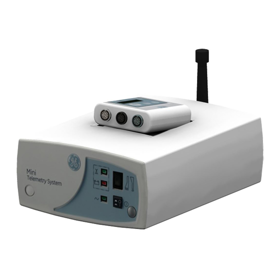
- Page 25 Chapter 3: Mini Telemetry Components This section describes all controls, indicators and connectors on a Mini Telemetry System. Transmitter Oblique View The following table describes the components of the Transmitter front panel: Component Description 1. Display: A display to show the charge status of battery, volume, connectors connectivity, Channel number and mark key.
- Page 26 Chapter 3:Mini Telemetry Components Component Description 3. Volume Key: If ultrasound transducer is connected, this key controls the volume of fetal heartbeat, heard on the speaker/ headphone. Multiple presses of this key will cycle the volume from mute to 5 volume levels.
- Page 27 Component Description 1. O ring: Ring for attaching the carrying strap. 2. DC in-let Connector: Connect the GE recommended power adaptor to this connector for charging the transmitter battery. WARNING: Always use only GE recommended power adaptor. 3. Headset Connector: Connect the headset to this receptacle to listen to the fetal heart rate derived from ultrasound.
- Page 28 Chapter 3:Mini Telemetry Components Battery Compartment The following table describes the components of the Transmitter battery compartment: Component Description The battery compartment holds 1 Lithium ion battery. Only authorized, trained personal shall open the battery compartment for any service related actions.
-
Page 29: Display Indications
Chapter3 :Mini Telemetry Components Display GUI The following table describes the Transmitter display GUI: Figure Description 1. Battery Charge Status: Indicates battery level and charge status. Indications continuously move while the battery is being charged. 2. Speaker Volume Status: 5 levels of volume and mute are indicated. -
Page 30: Receiver
Alarm tones will be deactivated when the Mini Telemetry transmitter is connected to the external power adaptor for charging. -
Page 31: Receiver Rear Panel
Chapter3 :Mini Telemetry Components Component Description 5. Channel Number: The channel number is the customer- designated frequency of the receiver. For each telemetry system, the channel number of the receiver must be identical to the channel number of the transmitter. - Page 32 Chapter 3:Mini Telemetry Components Component Description 5. Power cord holder clamp: To hold the power cord. Auxiliary Output Connector This connector outputs the US, ECG, UA and Mark signals acquired by telemetry to a compatible fetal/fetal-maternal Monitor. See “Connecting the Receiver and Monitor”...
-
Page 33: Chapter 4: Installation And Setup
IMPORTANT: 120 SERIES COMMUNICATIONS OPTION — A 120 series monitor requires a communications Board in order to interface to a Mini Telemetry system. If your monitor does not have this option, an upgrade kit is available as cat. no. (REF) 1559BAO. Contact your service representative for more information. - Page 34 Chapter 4: Installation and Setup Step Instructions Instructions to attach the Receiver Antenna: 1. Insert the receiver antenna into the antenna connector on the receiver rear panel as shown in the figure. Rotate the attachment collar in a clockwise direction until snug. NOTE: A Remote Antenna Bracket, cat.
-
Page 35: Setting Up The Transmitter
Chapter4: Installation and Setup Setting up the Transmitter Connecting Battery to Circuit Board NOTE: The battery of Mini-telemetry transmitter is shipped without being connected to the circuit board. Before using the telemetry transmitter, ensure that battery is connected to the circuit board. SENSITIVE TO ELECTROSTATIC DISCHARGE CAUTION This procedure involves handling of ESD sensitive parts. -
Page 36: Connecting Power Adaptor
Check for battery charge/full indication on the display. IMPORTANT : Power Adaptor —Use only the appropriate country specific plug attachments to the Adaptor. The Mini Telemetry system’s Adaptor comes with global plugin options. © 2010 by General Electric Company. All rights reserved. 2049809-001 Rev B... -
Page 37: Replacing The Plug Attachments
Chapter4: Installation and Setup Replacing the Plug Attachments Perform the following steps to replace the plug attachments. Step Instructions Instructions to replace the plug attachment: 1. Press and hold the Release button as shown in figure 1 and rotate the plug attachment anti- clockwise to release it from the adaptor. -
Page 38: Performing A Functional Checkout
Chapter 4: Installation and Setup Performing a Functional Checkout Initial Conditions Step Instructions Connect the receiver to the monitor as described in “Connecting the Receiver and Monitor” section earlier in this chapter. Turn on the transmitter, receiver and monitor attached to the receiver. -
Page 39: Testing The Ultrasound Functions
Chapter4: Installation and Setup Testing the Ultrasound Functions NOTE: TRANSDUCER TYPE—Use only Corometrics 5700 Series Ultrasound Transducers with the Mini Telemetry System. Perform the following steps to test the ultrasound functions: Step Instructions Instructions to Test Ultrasound Functions: 1. Plug an ultrasound transducer into the Ultrasound connector on the transmitter as shown in the figure. -
Page 40: Testing The Ecg Functions
Chapter 4: Installation and Setup Step Instructions 4. Plug the headset into the transmitter’s headset connector 5. Rub the face of the ultrasound transducer. Verify that you hear ultrasound audio tones from both sides of the headset or in the internal speakers (if head set is not connected) Testing the ECG Functions Perform the following steps to test the ECG functions. -
Page 41: Testing The Ua Functions
Chapter4: Installation and Setup Testing the UA Functions Perform the following steps to test the UA functions. Step Instructions Instructions to test UA functions: 1. Place the receiver’s UA Mode Selector switch in the TOCO position. IMPORTANT : TRIMLINE TOCOTRANSDUCERS—If the monitor is on when you connect or re-connect a Trimline Tocotransducer to the UA connector, you must wait at least 10 seconds before pressing the UA Reference... - Page 42 Chapter 4: Installation and Setup Step Instructions 4. Apply gentle pressure to the tocotransducer pressure sensing button and verify that the monitor (display or uterine activity trace) responds to the pressure input. Increasing force should produce an increasing value and vice versa. If no pressure changes are recorded, ensure that the corresponding interconnection cable is firmly attached to both the monitor and the receiver.
-
Page 43: Testing The Event Marker Function
Chapter4: Installation and Setup Testing the Event Marker Function Perform the following steps to test the event marker function. Step Instructions Instructions to test the event marker function: 1. Connect any transducer to the Mini-telemetry transmitter. Turn on the monitor’s strip chart recorder. -
Page 44: Monitoring Via Telemetry
Chapter 4: Installation and Setup Monitoring via Telemetry This section provides a brief overview of telemetry monitoring procedures. Refer to the “Maternal/Fetal Monitoring Operator’s Manual” for patient application information. Also refer to your monitor’s operator manual. Suggestions for Ambulatory Monitoring IMPORTANT : DESIGNATED AREAS—Show the patient the areas that are within signal range and where signal reception is clear. -
Page 45: Monitoring Reminders
Chapter4: Installation and Setup Illustration Description 2. Shorten the length of the transducer cables by winding it around the transmitter as seen in the figure to avoid tripping. 3. For additional transducer cable management use the velcro strips provided to arrest the transducer cables as shown in the figure. -
Page 46: Ultrasound
Chapter 4: Installation and Setup Ultrasound • Use only Corometrics 5700 Series ultrasound transducers with a Mini Telemetry System. • Remind the patient to use the headset / speaker to check for continual pickup of the fetal heart rate signal following each fetal movement. -
Page 47: Chapter 5: Maintenance And Cleaning
Chapter 5: Maintenance and Cleaning Maintenance This section describes general care and cleaning instructions for the Mini Telemetry System. Storage Place the transmitter on the placeholder of the receiver when it is not used. NOTE: The transmitter can be charged when placed on the receiver. -
Page 48: Shoulder Strap Cleaning
Chapter 5: Maintenance and Cleaning The following table lists approved cleaning solutions. Generic Formulation Maximum concentration level Hydrogen peroxide Sodium hypochlorite 100 parts per million (ppm) 100 % spray (apply on equipment sprayed on cloth- CaviCide® not directly on equipment. Shoulder Strap Cleaning 1. -
Page 49: Chapter 6: Troubleshooting
Chapter 6: Troubleshooting This section of the manual provides a troubleshooting guide for the Mini Telemetry System’s operational problems. If the response to a specific question is not found, contact service department. Refer to contact details mentioned in the back cover. - Page 50 Battery indicator on the receiver lights c o n t i n u o u s l y and Low Battery Recharge battery by connecting to the GE indicator Battery is low recommended power adaptor. displayed on the transmitter screen...
- Page 51 • Another transmitter with the • Discontinue same frequency is in use within transmitters. NOTE: Mini Telemetry can the same facility. be re-programmed to an alternative frequency. • Exceeding transmission range. • Install optional ceiling antenna system.
- Page 52 Information Technologies Service Representative. • Battery is low. • Recharge battery by connecting to the GE recommended power adaptor. Mini Telemetry transmitter switches off automatically • Battery overheating • Contact your Information Technologies Service Representative. “E1” is displayed on the...
- Page 53 Chapter 6: Troubleshooting Troubleshooting Problem Probable Cause Solution • Currently configured radio channel number is outside the supported range as specified Contact your Information Technologies Radio channel number does in service manual. Service Representative. not appear in the normal • Communication between the user screen on transmitter system and the radio module...
- Page 54 Chapter 6: Troubleshooting This page is left blank intentionally, © 2010 by General Electric Company. All rights reserved. 2049809-001 Rev B...
-
Page 55: Appendix A: Supplies And Accessories
Appendix A Appendix A: Supplies and Accessories This section provides an overall listing of supplies and accessories for use with a Corometrics Mini Telemetry System and with Corometrics Fetal or Maternal/Fetal Monitors. To order any of the supplies and accessories listed in this manual, refer to the addresses listed in the back cover. - Page 56 2049816-001 Mini Telemetry Operation manual-Japan 2049817-001 Mini Telemetry Operation manual-Korean 2049818-001 Mini Telemetry Operation manual-Portuguese 2049819-001 Mini Telemetry Operation manual- French 2049820-001 Quick Ref Guide – English 2049966-001 Quick Ref Guide - German 2049967-001 Quick Ref Guide – Dutch 2049968-001 Quick Ref Guide –...
-
Page 57: Appendix B: Technical Specifications
Appendix B: Technical Specifications NOTE: Specifications are subject to change without notice. This section contains a detailed list of the technical specifications for the Mini Telemetry System. B.1 Transmitter Transmitter Category Technical Specifications Power adaptor requirements Input voltage range :... - Page 58 Appendix B Transmitter Category Technical Specifications Certification and Compliance UL 60601-1 FCC: United States FCC 47 CFR Part 95 Industry Canada: Canadian RSS-210 European EN 300-220-1 Monitoring Modes Fetal Heart Rate: Ultrasound (US) and FECG Uterine Activity: External Tocotransducer (TOCO) or Internal Intrauterine Pressure Catheter (IUPC) Maternal Heart Rate: Maternal ECG (MECG)
- Page 59 Appendix B Transmitter Category Technical Specifications ECG Mode Input Impedance: >1 GΩ DC Tolerance: ±1 V Common Mode Rejection Ratio: >90 dB FECG Sensitivity: 30 µ V to 1 mV MECG Sensitivity: 0.5 mV to 5 mV Leakage Current: < 10 µA (TYPE CF) TOCO Mode Type: Tocotransducer...
- Page 60 Appendix B Transmitter Category Technical Specifications Battery Technology: Li-Ion battery pack (2 cells) 7.2 VDC nominal Capacity: 2600mAh Recharge time: 4 hours Backup: Approximately 12 hours when fully charged Quick charge: 2.5 hours backup when recharged for 30 min Audio Indicator: Low Battery Internal speaker Audio output:...
- Page 61 Appendix B Transmitter Category Technical Specifications RF Section Power Output: Frequency Band : Power Output 420.0500 - 429.7375 MHz: 1mW 432.0000 - 438.0000 MHz: 4mW 440.5625 - 449.6625 MHz: 1mW 608.0250 - 613.9750 MHz: 4mW Channel Bandwidth: Frequency Band : Channel Bandwidth 420.0500 - 429.7375 MHz : 12.5kHz 432.0000 - 438.0000 MHz : 25kHz 440.5625 - 449.6625 MHz : 12.5kHz...
-
Page 62: B.2 Receiver
Appendix B B.2 Receiver Receiver Category Technical Specifications Power Requirements Nominal Line Voltage: 100-120VAC 220-240VAC Fuse 0.25A T Fuse 0.25A T Line Frequency: 50/60Hz Power Consumption (maximum): 30 W Touch current: <300µA Physical Characteristics Height: 4” (10.2cm) Width: 8.1” (20.6cm) Depth: 11.9”... - Page 63 Appendix B Receiver Category Technical Specifications RF Section Input Impedance: 50 Ω Input Sensitivity: <0.4 µ V for 12 dB SINAD Antenna Type: Flexible, detachable, BNC interconnect (Other factory-approved external antennas or antenna systems may be used. Contact your Information Technologies Service Representative for more information.) Controls: Power Switch, UA Mode Switch...
- Page 64 Appendix B This page is left blank intentionally. 2049809-001 © 2010 by General Electric Company. All rights reserved. Rev B...
-
Page 65: Appendix C: Electromagnetic Compatibility
Appendix C: Electromagnetic Compatibility C.1 Electromagnetic compatibility (EMC) guidance Safety Standards: IEC 60601-1, IEC 60601-2-37, IEC 60601-2-49 EMC Standards: IEC 60601-1-2 WARNING: Medical Electrical Equipment needs special precautions regarding EMC and needs to be installed and put into service according to the EMC information provided below. WARNING: Portable and mobile RF communication equipment can affect Medical Electrical Equipment. - Page 66 Appendix C Electromagnetic immunity Electromagnetic environment Immunity Test IEC 60601 Test Level Compliance level guidance ± 2kV for power supply ± 2kV for power supply Electrical fast line. line. Mains power quality should be that of a transient/burst IEC ± 1kV for input/output ±...
- Page 67 Appendix C International Electrotechnical Commission (IEC) guidance and manufacturer’s declaration regarding electronic immunity The unit is intended for use in the electronic environment specified below. The user of the unit should ensure that it is used in such an environment. Electromagnetic immunity Immunity IEC 60601...
- Page 68 NOTE b: Over the frequency range 150 KHz to 80 MHz field strengths should be less than 3 V/m. Recommended separation distance between portable and mobile RF communications equipment and the Mini Telemetry The unit is intended for use in an electromagnetic environment in which radiated RF disturbances are controlled.
-
Page 69: Appendix D: Warranty
For a period of twelve (12) months for the product from the date of original delivery to Buyer or to Buyer’s order, but in no event for a period of more than two years from the date of original delivery by GE... - Page 70 Appendix D This page is left blank intentionally. © 2010 by General Electric Company. All rights reserved. 2049809-001 Rev B...
- Page 71 Shanghai, People’s Republic of China 201203 Tel: +86 21 5257 4650 Fax: +86 21 5208 2008 GE Medical Systems Information Technologies, Inc. 8200 West Tower Avenue Milwaukee, WI 53223 USA Tel: + 1 414 355 50001 800 558 5120 (US Only)