
Related Manuals for GE OPTIMA MR360


Summary of Contents for GE OPTIMA MR360
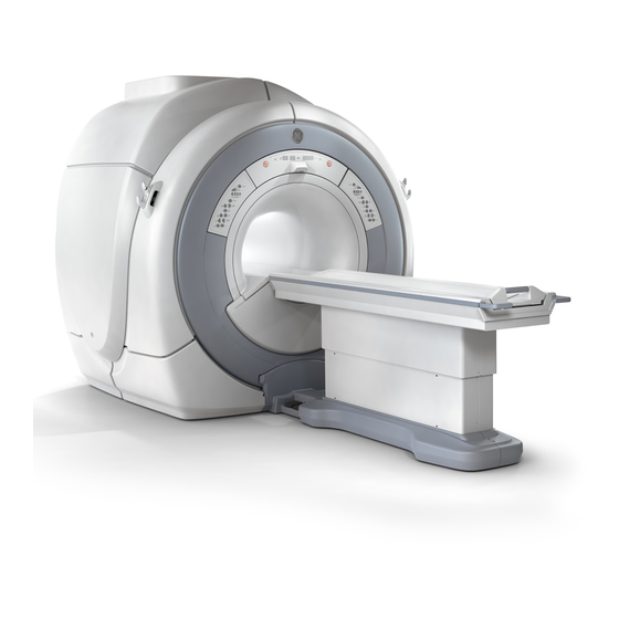
- Page 1 OPTIMA MR360 & BRIVO MR355 FULL SERVICE TRAINING REV 1.5 ATC MR INSTRUCTOR XIAO XIAO GE ASIA TRAINING CENTER...
- Page 2 Content Module 1 - Course Introduction & Safety..............1 Module 2 - System overview………………………………………………………………………….14 Module 3 - New User Interface and Software Operation……………………...65 Module 4 – Architecture & Hardware…………………………………………………………..87 Module 5 – Calibration & Diagnostics……………………………………………………….169 Lab Guide & Component Identification…………………………………………………...193...
- Page 6 Excite HD training is a pre-requisite for this course. If you haven’t been trained on Excite HD, it is mandatory to get the HD training before you will be able to be successful in the SV course.
- Page 9 There are three types of safety hazards to be aware of with MR. Always observe high voltage dangers and perform Lock Out / Tag Out (LOTO) safety steps before working on any piece of MR equipment. Do not substitute a shortcut process for LOTO.
- Page 10 Be sure to be cautious when installing or replacing anything in the magnet room, especially in the 3.0T environment. Test items first for ferrous properties. Never put your body between the magnet and anything that may be a ferrous material. The 3T magnetic field requires extreme caution.
- Page 11 The portable GasWatch2 Oxygen sensor as pictured above - part number is 5111049...
- Page 12 Due to the magnet top off you may have to sting the magnet and handle dewars during this fill. The gas cylinders must be strapped down and when not in use have their cap on, also be very careful of the dewars. In most cases, Air Products or a cryogen contractor will take care of this task, but you should be aware of this in case you need to perform it.
- Page 13 LOTO Service Documentation is Accessible via the Service Methods Website by clicking on “Safety” and then the correct procedure name under “Lock Out Tag Out”. Note that for SV, all LOTO procedures involving LOTO of the SYSTEMS CABINET require shut down of the Simple OC first. This is because powering down the Simple OC ensures correct soft power down of the Image Compute Node.
- Page 19 Compared to the HD system, SV changes lots of components. • Air cooling system is replaced by water cooling system for RF amplifier and Gradient amplifier. • System cabinet, HFD cabinet and part of penetration panel are combined in one compact cabinet.
- Page 22 If you refer to the MR Service Docs for 5364191-2EN - Optima MR360 / Brivo MR355 1.5T Service Methods>Replacement>Magnet Enclosure>Magnet Enclosure Table of Contents you will see the same diagram with clickable links for each component. These links will take you to the procedures for removing and reinstalling the covers.
- Page 23 Refer to the service manual for detail procedure of replacement: 5364191-2EN - Optima MR360 / Brivo MR355 1.5T Service Methods>Replacement>Magnet Enclosure>Magnet Enclosure Control Panels SV, HDe, HDx Forward Production Control Panels: • Same function as control panel in HD except for the appearance •...
- Page 24 Important facts about the LPCA of SV: • There is no head T/R switch. T/R switch is moved to the Quick disconnect of the Split head coil and Quad knee coil. • Port A is a coil interface for coils with and without preamps •...
- Page 25 Rear Pedestal is newly designed. 1. The 16ch Switch is not used in SV system, which is functionally replaced by Mega Switch located on the Magnet Side kit. 2. LED Power Box is introduced, which is the power supply for SRI, PAC, Patient alignment laser and bore light.
- Page 26 • Magnet side kit contains Voltage Regulator Box, Mega Switch, RRX, cables and base plate. It is mounted on the left side of the magnet through insulating board, and a ground wire is connected between base plate and system cabinet. •...
- Page 27 • Fixed table has no Dock and Undock function like detachable table. Up and down of fixed table are implemented by actuator, which is driven by electrical motor. The table can go up and down very smoothly with very low noise compared to the detachable table. And there is no other mechanism to drive fixed table up and down.
- Page 28 Express coil consists of three parts: 1) HNA, functionally similar to NV coil; 2) PA, functionally similar to CTL coil; 3) AA, functionally similar to 8Ch body array or 4Ch torso coil. HNA and AA are removable coils that connected to Port A in LPCA. PA coil is embedded in the cradle of the fixed table, which can be moved in and out of the magnet bore with the cradle.
- Page 29 The trough on the newly designed Front Bridge is used to holding the cable track on the bottom of the cradle.
- Page 30 For the reason of cost down and simplication, some coils use the unified phantom to replace their own phantom. Refer to service manual for detail procedure of SNR test. Unified phantom also can be used in HDe, HDx after the corresponding service pack is installed.
- Page 31 • In all GE MR systems prior to SV, HDe and HDx, the keyboard and mouse communicated via PS2 port. • The SV system uses an optical mouse and both the keyboard and mouse communicate with the host via USB.
- Page 32 There is only one system cabinet that covers the function of RFS, HFD cabinet and part of penetration panel. The following two slides show the inner components under the covers. Note: 1) Store L/R cover carefully to prevent the distortion 2) Take care of G-Filter and power panel when moving the cabinet...
- Page 34 There are three access window on the back of the system cabinet. 1. Access window for back of CAM Lite2 and GP3, ICN are used during installation. 2. Access window for PDU FRU only be used during replacement...
- Page 35 The gradient system in SV is called XFD. It contains three gradient amplifiers XFA and one gradient power supply XFD-PS. They are all water-cooled. A leak sensor is installed in front of XFD to detect leakage of water pipe connectors. XFD slew rate is 100, which is twice as much as HFD-lite used in HDe system.
- Page 36 In order to improve gradient system service capability, traditional cables and connectors are not used for connection between XFAs and XFD-PS in SV system. XFD-PS power output and XFA power input are used plugs and sockets, which is connected by a newly designed component, Power panel.
- Page 37 Power panel connects XFAs and XFD-PS. It can be accessed by removing its cover in the magnet room. If the power panel needs to be replaced, be assure to wait for at least 15 minutes after XFD power-off. And the nethermost plug must be removed before removing other plugs.
- Page 40 There are 108 screw holes on the frame connected to the system cabinet. But only 60 screws are supplied. Fix the System Cabinet with washer and screws at every two hole pitch. Do not install screw in every hole.
- Page 42 The three phase alternating current for MCS and 8KW LCS must have the correct phase position to operate. If the phase rotation is incorrect, there is no indication of power to the system. Swap two phase leads, observing LOTO precautions. The 4KW LCS doesn’t have this requirement.
- Page 46 • There are five kinds of water cooling system configurations. • Type A, B and C have their individual plumbing assembly. • In type B and type E, Facility water is provided by the customer. The water should meet the specification in the pre installation manual. In not, it is possible to damage our equipment.
- Page 57 In previous installation of outdoor water chillers, the vendor used different valves for connection. The quality can’t be assured by this way. Now the Plumbing Assy will be shipped to site according to the different configuration of cooling system.
- Page 58 In order to meet the market requirement, SV system contains two kinds of configuration: Optima MR360 and Brivo MR355. For the customers who are familiar with GE MR system, Optima MR360 can provide affordable, versatile MR scanning to meet everyday patient needs with uncompromised(uncompromising) imaging, workflow, service and support.
- Page 59 In general, Optima MR360 & Brivo MR355 have the same basic hardware configuration. Fixed Table with Express coil can be used in both Optima MR360 and Brivo MR355. Detachable Table can only be used in Optima MR360.
- Page 60 • The software options available in MR360 are more than that in MR355, which means MR360 is more powerful than MR355. • Optima MR360 can use all kinds of coils. Brivo MR355 has four kinds of configurations . Only the coils included in the configuration can be used, which is controlled by the Option key.
- Page 61 • There is no this limitation in Optima MR360. But MR360 has to follow another limitation according to different table type.(Refer to the next page)
- Page 63 • For type B of HDe with air cooled shield cooler, shield cooler will be reused. No need to remove. • Optima MR360 configurations upgraded from HDe are Type C and Type D with detachable table. • For detailed information, refer to Signa HDe to Optima MR360 System Upgrade Manual...
- Page 64 Brivo MR355 can be upgraded to Optima MR360 after uninstalling the previous one of Brivo option keys and installing MR360 Option Key. No hardware change is needed.
- Page 70 With Favorite Protocol, users can select their favorite protocols at hand graphically instead of opening protocol selector window. It has two kinds of favorite protocols: • Ready Favorite Protocols, also called Ready Shortcuts • Custom Favorite Protocols, also called custom shortcuts Ready Favorite Protocols are predefined and cannot be changed by users.
- Page 72 Simple UI is designed for inexperienced customers who can't and those who don't want to handle complicated MR physical parameters as “novice mode”. It allows switching to “Advanced” and “Expert” UI modes at any time (except after the task is saved). The inexperienced users can finish the routing scan in Simple UI.
- Page 73 The Advanced Scan Mode and Expert Scan Mode is to control all scan parameters in detail. The scan mode can be switched when the [Mode change] button is selected.
- Page 74 Default Scan Screen mode can be set as System Preference. The default Scan Screen mode applied at the beginning of the exam. Note: Scan Screen mode is kept in a exam until the mode is changed.
- Page 75 1. Tradeoff is shown on the slider bar. Basically the SNR is kept for all positions, but the spatial resolution is different. 2. Following scan parameters are propagated to the other position of the Slider Bar. Scan plane, Start/End location, Auto shim, Tracker length/thickness, Patient entry/position, Coil configuration, Series description, Contrast information 3.
- Page 76 Protocol Selector are totally different from the previous version. There are the specific user interface for Adult and Pediatric protocols.
- Page 77 Protocol Template only can be accessed in GE protocol library. In this template, all the common used protocol can be found.
- Page 78 Image can be previewed in this new version of Image Management.
- Page 83 You can access the same diagnostic items by System Function or Hardware Location. Their functions are same.
- Page 84 Protection is enabled, the field service personnel will be required to input an authorization code to access the service browser to utilize GE proprietary tools. The authorization code can be generated automatically in the back-office sever after one IPP Key is input that is generated by MR host software.
- Page 86 The E-Reporting Tool is a web-based application that allows for better communication between the customer and the GE service engineer. Communication is one-way with this tool from the service engineer to the customer. When a Field Engineer (FE) or Online Engineer (OLE) provides service at a customer site, the E-Reporting Tool is used to document issues found or service performed.
- Page 87 In SV systems, it is easy to enable or disable autologin function. If the current mode is unclear, use the STATUS function to check.
- Page 92 It is also used in other areas such as industrial automation and medical equipment. Since MGD was introduced into GE MR system, CAN replaces the MDS link gradually. In different systems, the components connected through CAN link are different.
- Page 93 This graphic displays the Ethernet routes and serial service for the SV system. • Because CAM lite2 has no APS, so port 1 in Term Server is not used any more. • Image data, status and control signal are transferred by the 1000M Ethernet switch. •...
- Page 94 The Common MR Communications Link is first used in the DVMR product development. In SV, we use the same communication link. SerialLite is a serial protocol developed by Altera Corp. and Innocor Ltd. Altera provides an IP core implementation of SerialLite that utilizes the high-speed serial transceivers in their Stratix GX FPGAs.
- Page 95 This block diagram shows RF receive chain in SV system. If the system configuration is MR360 without Express coil, J22 in Mega Switch has no cable connection. Mega Switch selects different input signal from Port A coil, PA coil and body coil, and amplifies the selected signal, and converts them to intermediate frequency signal, which center frequency is about 16MHz.
- Page 98 During RF transmitting, Unblank signal will be generated and sent to synchronize remote devices. Digital Unblank signal is sent from CAM lite to Exciter via DVMR link. The analog Unblank signal is generated by the Exciter. Then, the analog Unblank signal is sent to Driver module lite Unblank distributor, which outputs same Unblank signals and sends to UPM1, UPM2, RF amplifier interface board and SRFD3.
- Page 99 PCIAA is functionally similar to GOCAA (Global Operator Console Audio Assembly), but is only used for audio communication between operator and patient. It locates in the host PC and is mounted on one PCI socket. But PCIAA has no any electrical connection with PCI socket, only occupies one PCI slot to fix.
- Page 100 Simple OC consists of host PC and chassis. Host, LCD and Ethernet switch get the power supply from the power strip in the chassis. There is a circuit breaker on the power strip, which can only be accessed after right cover removal. Pay attention to the service key after inserted in the front USB port.
- Page 101 The input power for THTF host should be 100~240VAC. SCSI tower isn’t used in SV system any more. Only one DVD-RW driver is installed in the host. LFC, save and restore info are all executed by this driver. It is fixed by two screws on the left side.
- Page 102 This slide shows the detailed configuration of THTF host.
- Page 103 • PCIAA (PCI Audio Assembly) Kit contains one ribbon cable and two boards: PCIAA board and PCIAA Extended board. • There are several audio adjustment potentiometers on the PCIAA extended board for adjusting patient and operator voice levels. The Minimum Patient Speaker Volume is fixed, there is no adjustment for it.
- Page 107 • Due to 2.15 Farad super capacitor used in gradient power supply, the rated power of system cabinet PDU is decreased to 25KW. • 3 phase lines and 1 ground wire are connected between MDP (Main Disconnect Panels) and PDU. •...
- Page 108 The 25KVA is a new design part. The power capacity is less than former products because the gradient power supply uses the super capacitors to store power energy in SV system. Control signals to Main Breaker: 1. Power Off Button Control: This signal is from Power Off button. Main breaker will trip if press this button.
- Page 109 2. Output control signal: a. E-Off Contactor Trip Control b. Night Mode Contactor Trip Control c. Main Breaker Trip Control: In HDe system, when leak sensor 1 detects any leakage, cabinet monitor will send control signal to PDU to trip the Main Breaker. The whole system will lost power input.
- Page 110 MPS (Magnet Power Supply) is for ramping up power supply. It will have no output after E-stop contactor is tripped.
- Page 111 There are five Switching AC to DC power supplies located on the upper right of the system cabinet. DCPS for DM_Lite, Exciter, Mega SW & RRX only have input power 120VAC, no control signal, which means that the three DCPS have stable and uncontrolled output once the input power 120VAC is engaged.
- Page 113 1.Overview The PHPS stands for Patient Handling Power Supply. It functionally replaces the SSM (System Support Module). There are three types of PHPS for different type of MR. The above table shows the difference between PHPS, PHPS-Lite and PHPS-Lite2. 2. Basic principle The PHPS-Lite2 is mounted in the Cabinet.
- Page 114 1) The Control Board Assembly gets command signal serially from IRF I/O J23 in CAM-Lite2 cabinet. The Control Board generates signals needed for control of the following entities: • The Patient Alignment Laser • The Bore Light • The Patient comfort fan relay •...
- Page 115 CAM Lite is short for Consolidated ASC MGD Lite chassis. It consolidates the components of the Multi-Generational Data acquisition chassis (MGD) and Amplifier Support Controller (ASC) chassis into one unit on HDe forward production Systems cabinets. The CAM-Lite chassis combines the individual ASC and MGD boards into a common chassis.
- Page 118 The CAM-LITE2 is a consolidation of two subsystems, the MGD LITE and ASC LITE. It contains a custom 6U cPCI midplane that is comprised of a single custom bus segment, two cPCI bus segments and a common power system. The single custom bus segment house the Universal Power Monitor (UPM) circuit card that provide RF amplifier power monitoring function with redundancy and the Amplifier Interface (AIF) circuit cards for the Narrow Band (NB).
- Page 119 AGP(Applications Gateway Processor) or the AGP2 include a cPCI(Compact PCI) single board computer. The AGP consists of a Motorola MCP750 or equivalent, and include a 64MB memory mezzanine module. The AGP-II consists of a Motorola MCP820 or equivalent, and include a 128MB memory mezzanine module. So AGP2 Board (Slot 6 F) is also sometimes referred to as MCP820.
- Page 120 66 MHz SDRAM components on the CPV-3060 • Memory array capacity: the SCPIII processor offers 64–512 Mbyte capacity at the main memory array, compared to the 64–128 Mbyte capacity offered on the CPV-3060. The RAM configuration for GE part is 256M.
- Page 121 The IRF3 is the third generation Interface and Remote RF Functions circuit board. It is designed for use within the DVMR system and, despite many architectural similarities, maintains no backwards compatibility with IRF or IRF2. The IRF3 primarily serves as a communications hub within the CAM chassis, supporting communication with one or two Remote Receiver devices (RRx), one or two Remote Exciter devices (DTx), and the XGD gradient subsystem via five identical high-speed (2Gbit) serial fiber optic interfaces implementing the DVMR Common Communications Link.
- Page 122 The RF Amplifier Support Chassis (ASC) will house two complete Universal Power Monitors for redundancy. A UPM will consist of a UPB and up to two UPM RF Detector Boards (RFD) connected on the ASC Backplane. Each UPM will be capable of monitoring forward and reflected RF power in a MR system for 0.35T to 3T range of field strengths.
- Page 123 Driver Module Input and Output Signals: 1. Head T/R Bias (J6) to SRFD3: +8VDC(@4.25A)/-14.4VDC(@400mA) 2. Body T/R Bias (J7) to SRFD3: +5VDC(@5.5A)/-14.4VDC(@400mA) 3. Dynamic Disable Bias (J21/22/24/25) to Body Coil: 500VDC/ -1A(@-3.7VDC) 4. Direct Drive Bias (J23) to Body Hybrid: 500VDC/-1A(@-3.7VDC) 5.
- Page 125 RF Exciter Outputs 1. Analog RF excitation signal 2. 80MHZ Clock signal to VRF, IRF3, Mega Switch and RRX via Mega Switch 3. Local Oscillator (LO) signal and Loopback for Mega Switch 4. Unblank signal to Driver Module and magnet monitor...
- Page 126 The VRE(Volume Reconstruction Engine ) replaces the Array Processor in the Signa HDx, HDe and SV systems. It does the image processing and reconstruction functions that were previously done by the Reflex AP's in the Excite2A and Excite HD systems. The VRE in the SV system has only one ICN (Image Compute Node).
- Page 127 VRF board contains an optical interface to receive scan data from Remote Receiver (RRx) board, filters the data and DMAs the data to the ICN for image reconstruction. The VRF board is physically installed in PCIs slot on the ICN. The VRF will receive an 80MHz reference clock from the exciter board.
- Page 128 The SRFD3 RF Amplifier and Interface (SRFD3 Module) is the third phase in the development of the Scaleable RF Driver (SRFD) subsystem. It is the first liquid cooled amplifier and lower output power(10kW). The SRFD3 Module performs the following functions: Head/Body mode switching, CAN communication link decoding, control and status communication between the system and the RF amplifier, RF power amplification, and RF power sampling for power monitoring by the Universal Power Monitor (UPM).
- Page 130 SRFD3 has been pre-adjusted in factory. You don’t need to adjust RF power on site during installation. Because the card 72 in the RF Power Measurement Kit is for 16KW power output, it is necessary to modify the measurement method.
- Page 132 Performance: Water cooling gradient system Slew Rate: 100 T/m/s G-Max: 33 mT/m Input : 208VAC, 1A ; 200VDC&700VDC Output: 300A for 100ms, 1400VDc Cal/Function Check: DC offset, DQA cal Diagnostic: Hammer, Frame/Clk test, ECC Verification, Hysteresis Static Test is obsolete. FRU: XFA, XFD-PS, Control Boards Install/Replacement: 1) Quick disconnecting design to facilitate the replacement.
- Page 133 The XFD-PS is an IGBT-based switching Power Supply. It can output three sets of DC +200V, +700V and -700V. The XFA needs the three kinds of voltages. There are two serially connected 4.3 Farad supper capacitor (EDLC: Electrical dual layer capacitor) in 200V DC power supply.
- Page 134 The part is the 200V DC power supply for three XFAs and 200V to 700V DC-DC power supply.
- Page 136 Three sets of DC700V and -700V are isolated.
- Page 137 XFA is an IGBT-based switching amplifier. It provides a voltage to overcome the inductance and resistance of the MR gradient coil. The XFD-PS powers the three XFAs. Actually, the ideal output of XFA is a square wave. In order to decrease the time of rising edge, XFA will output DC 1400V energized on the G-coil.
- Page 138 The XFD-PS weigh 87kg. Be strictly follow the replacement procedure in the service manual. In case the connections are difficult to remove, follow Method B.
- Page 139 RF amplifier, gradient amplifiers and gradient power supply are all water-cooled in SV system cabinet. Leak sensors are used to detect if there is leakage happened on any water pipe connectors. Leak sensor is composed of two parallel wires that terminated by a 8.3MOhms resistor at one end.
- Page 140 Leak sensors are classified three levels. Leak sensor 1 is the highest level, which is only used in HDe system and will trip the PDU main breaker. In SV system, only Leak sensor 2 and 3 are used. Leak sensor 2 consists of three parts: Front, Bottom and Water Tray. Front sensor locates in front of RF amplifier and XFD;...
- Page 141 Function: 1. Cabinet monitor will trip the E-Off contactor in the PDU when a) Leak Sensor 2 detects water leakage or are open Temperature of system cabinet is over 45 degree centigrade c) 4KW LCS or 8KW LCS/MCS stop working 2.
- Page 144 • PS for Mega SW & RRX provides three kinds of input voltage to Regulator Box through the filters in the System Cabinet Interface Board(SCIF). But the cables from the SCIF connectors to Regulator Box are very long, which will surely cause voltage drop on the cables.
- Page 145 All the input, output and power good LED indicators can be observed through the heat dissipation holes of the Regulator Box. Due to no power supply for MNS, Input LED DS12 and Output LED DS1 are off all the time, and other LED indicators are continuous lit.
- Page 146 Voltage Regulator Board monitors all regulated voltages using comparator chips and sends status information to Mega Switch. The output from the monitoring circuit is buffered and sent to Mega Switch as a 3.3V digital signal of wired-AND logic. Diagnostic information is provided on the front panel via LED’s.
- Page 148 The Mega Switch can be divided into ten modules: 1. RF Router: It is a multi-way switch, which routes the four RF inputs to one RF outputs. 2. Loopback Interface: It is used to distribute loopback signal from Exciter to all receive chain for R1 calibration and diagnostics.
- Page 149 1. The Mega Switch provides the RF routing circuit which routes the four RF inputs to one RF outputs. The main functions of the RF router block are as following. • Provide the receive Interface of RF signal • Route the RF receive signals to proper down conversion channels. •...
- Page 151 4. Driver Module Interface has the following functions: a) Multi Coil TR Bias The Mega Switch receives Multicoil TR bias (MCB) from the Driver Module Lite and these signals are routed to each coil port. The MC TR bias is specified as following: MC TR bias input (Transmit Mode) supplied by Driver Module MC Driver board +3, +5 or +7V +/- 0.1V @ 500mA Maximum MC TR bias input (Receive Mode) supplied by Driver Module MC Driver board -5 V +/- 0.1V @...
- Page 152 6. The control signals from the Driver Module is decoded and the following signals are generated. • RF Router Control Signals (To RF Router Block) • RRx Reset Signal (To RRx) • External MUX Control Signals (To Coil Ports) : The CPLD just pass though this signal to each Coil Port.
- Page 153 8. Clock Interface The Mega Switch receives 80MHz Master Clock from Exciter. The clock signal is band pass filtered to reduce the noise from the system, and routed to a LVPECL buffer to convert sine wave to LVPECL signal. The converted clock signal is transmitted to the RRx module through TNS interface connector. 9.
- Page 155 The Remote Receiver’s main function is to provide analog and digital signal processing and A/D conversion for 8 channels of data. Key functions of the RRx Module are: - 16-bit Analog-to-Digital conversion - Digital decimation and filtering - Synchronous transfer of 8 channels of 18-bit two’s complement I-data and Q-data from the FPGA over the DVMR Common Communications link at sample rates of 500kHz (+/- 250kHz) - Communication link to and from Megaswitch for diagnostic and control signals...
- Page 156 LED DS2, DS3, DS4 used to identify the Receiver Module number in binary format. LED DS1 is used to indicate when the Mega Switch +3.3V incoming power is good and is not lit when either the Mega Switch power is down or the cable into connector J1 is not connected. DS1 is used to prevent a false RRX1 indicator, where Port ID is equal to ‘000’.
- Page 157 Pin function in Port A Connector: A1, A2: Coil present A3 ~ A10: M0~M4 signal from Mega SW to control multicoil C1 ~ C4, D1 ~ D4: Ch1 ~ Ch8 preamp out, no bias, DC blocked E1: Transmit signal up to 2KW for 1.5T or 4KW for 3.0T. Peak Power E6: Reflected power to 50ohm load, 2.5KW Peak Power, 50W RMS F1 ~ F8, G1 ~ G8: Multicoil T/R bias F9, F10: To detect if this coil needs body coil to transmit...
- Page 158 • Fixed table has no Dock and Undock function like detachable table. Up and down of fixed table are implemented by actuator, which is driven by electrical motor. The table can go up and down very smoothly with very low noise compared to the detachable table. And there is no other mechanism to drive fixed table up and down.
- Page 159 There are five limit switches in the Fixed table. 1. One Home Sensor Limit Switch. Only when cradle moves to the home position, the Home sensor Limit Switch will be activated to allow the fixed table to be moved up and down. It can only be accessed for service by removing the top right cover.
- Page 160 The table control board is a newly designed part, which is fixed on the dock frame shipped with the fixed table package. • PS for PHPS-LITE2 supplies DC 42V power as the input of table control board through SCIF board. Then table control board outputs two direction power to the electrical actuator in the fixed table.
- Page 161 Please refer to the service method 5364191-2EN 'Replacement / Fix Table / TABLE ELECTRICAL ACTUATOR' for the detailed procedure.
- Page 162 Express coil consists of three coils: HNA, AA and PA. 1. HNA and AA can’t be used together because of one port A. 2. HNA and PA can use together. 3. AA and PA can use together.
- Page 163 HNA coil consists of three parts: Anterior part, Posterior part and Horseshoe adapter. There are 14 elements in HNA. Not all the elements will be used during scanning. Different elements will be used in different scan mode. HNA itself has four scan modes, which are Brain, NV, C Spine, C spine with adapter. And CT Spine mode can only be available when combining HNA and PA.
- Page 164 AA coil consists of four elements. It can’t be used independently, and must be used with PA coil, which their combination is functionally similar to 8ch Body Array or 4ch Torso Array. They have three scan modes – BodyArray12, BodyArray_23 and BodyArray_34, which will be shown on the next slide.
- Page 165 PA coil consists of 12 elements. In the surface of cradle, there are coil marker from 1 to 4. Every one marker contains of 3 elements. They have three scan modes – SpineArray_12, SpineArray_23 and SpineArray_34.
- Page 166 This table shows all the scan mode which the HNA, AA and PA have, and which elements will be used in different mode.
- Page 167 There are three modes for Express coil MCQA. Phantom position and landmark position would be strictly followed otherwise failure of MCQA. Be sure to use the foam pad in the HNA when scanning HNA+PA mode and HNA with Adapter + PA mode. Please refer to specific procedures of Express coil MCQA in the service manual.
- Page 168 • Automatic coil selection function can simplify the scan operation. The operator doesn’t have to know exactly what scan mode should be selected. The system can automatically select the suitable mode according to the landmark position. This function is only available for Express coil, and not all the scan modes of the Express coil are compatible with this function.
- Page 169 Please refer to the service method 5364191-2EN 'Replacement / Fix Table / Express Coil: Posterior Array Coil Replacement without removing Fixed Table' for the detailed procedure.
- Page 173 It is important during new installations and upgrades, to verify that your IP addresses are always up-to-date (both Host IP and MGD IP). If any changes have been made to an IP address, you must reconfigure the the ICN.
- Page 175 There are some steps during the installation of the MR system that must be done but for which the system has no “machine” data. For these items the system will rely on the user to check off the items as they are complete and click [Submit]. For all calibrations that have machine data, the tool can be launched the same way it was launched in previous versions of MR software –...
- Page 177 How to read this matrix: The same tasks calibrations are listed along the top and along the side. The ideal order of task / calibration completion is from the top to the bottom. Anything with no red squares to the right has no pre-dependencies, therefore it can be run at any time. If there are red squares to the right of any of the tasks/calibrations, then the tasks/calibrations indicated in the vertical column(s) associated with each red square must be completed successfully before that task/calibration becomes available.
- Page 178 Every time the user clicks on the “Calibration” tab of the CSD, as long as there is a service key plugged in, the ICW will be the only link available. Once all steps in Install Mode have been successfully completed, Maintenance Mode becomes available. In Maintenance Mode, any time you click on a calibration it will alert you to the possibility of pre- and post- dependencies.
- Page 179 This matrix is the basis for the logic of the ICW in Maintenance Mode. If you click [More] on the pop-up from the previous slide, this is the matrix that you will see. It is good to become familiar with how to read this matrix so that when you perform re-calibrations at sites you will understand what it means.
- Page 181 Before using the software to do the LVShim, LVshim localizer scan must be done to assure the phantom is in the center.
- Page 182 Insert appropriate DQA-III Phantom into head coil. Verify phantom is inserted into head coil. Also verify phantom is not rotated within the head coil. The correct phantom type, position and landmark are all critical to successful operation of the DQA-II tool. If there is a failure during the DQA-II tool, the “Actions Required”...
- Page 183 This new style 6-channel Grafidy fixture couldn’t be easier to use! It is simply a “plug and go” tool, meaning that when it is taken out of the box all that is required is that the user attaches the adaptor cable to the fixture and plugs it into the LPCA A-Port connector, unfolds the wings of the fixture, landmarks and begins the Grafidy calibration.
- Page 184 Along with the new 6-channel Grafidy fixture defined in the previous slide, improvements have been made to the Grafidy calibration’s data acquisition and software. The tool first verifies proper fixture placement and signal from all channels. It then acquires data simultaneously from all channels, thus reducing calibration time.
- Page 188 The report file is stored in /export/home/signa/bin.
- Page 191 The Multicoil Receive Chain Tool provides a means of diagnosing problems in Multicoil Receive (MCR) chain hardware, without use of coils. The tool sends signals down the individual paths to isolate specific channels in the receive chain. The tool’s Graphical User Interface (GUI) guides the user through the various steps involved in running the tool and troubleshooting the problem.
- Page 192 The RF and DC cables for Express PA Coil - Cradle mode are shipped with the system.
- Page 194 Optima MR360 / Brivo MR355 GEHC-TECH-MD33392427 MR5047 Service Training Lab Guide Rev Number: J MyWorkshop Book Number: 51232...
-
Page 195: Table Of Contents
GE Healthcare MR5047 SV Lab Guide Table of Contents TABLE OF CONTENTS.......................... 1 1. SYSTEM GEOGRAPHY LAB ......................2 2. OPERATION LAB ..........................4 3. CAN LINK LAB ..........................5 4. DVMR LINK LAB ..........................7 ... -
Page 196: System Geography Lab
GE Healthcare MR5047 SV Lab Guide 1. System Geography Lab The purpose of this lab is to investigate and identify the major Description: components of the MR360 / MR355 System. Time Required: 1 Hour Learning Identify the major subsystems and functions of the SV system... - Page 197 GE Healthcare MR5047 SV Lab Guide 7. For Fixed Table a. View component locations Do not disconnect any cabling 8. For Water Chiller a. View component locations Do not disconnect any cabling 9. System Power-On a. Follow power and software restoration procedure in Service Methods 5364191 If subsequent labs are to be performed –...
-
Page 198: Operation Lab
GE Healthcare MR5047 SV Lab Guide 2. Operation Lab The purpose of this lab is to understand basic operation procedures Description: of the MR355/360 scanner. Time Required: 2 Hour Learning Operate the system, as outlined in the service documentation. ... -
Page 199: Can Link Lab
GE Healthcare MR5047 SV Lab Guide 3. CAN link Lab Description: This lab will familiarize the student with the CAN Link Diagnostic Time Required: 1 Hour Navigate the service documentation Learning Understand how the CAN Link works in SV system ... - Page 200 GE Healthcare MR5047 SV Lab Guide j. Perform step 1 and record the test result _______________________________________________________ k. Remove connectors J1 and J2 from PHPS Lite2, and connect them together l. Perform step 1 and record the test result _______________________________________________________ m. Restore all the cables 1.
-
Page 201: Dvmr Link Lab
GE Healthcare MR5047 SV Lab Guide 4. DVMR Link Lab This lab will familiarize the student with the DTX board level Description: diagnostics and DTX to RRX data path 2 Hour Time Required: Navigate the service documentation and perform board and data ... - Page 202 GE Healthcare MR5047 SV Lab Guide k. Record results: ____________________________________ Use command mgd_term to open SCP and AGP terminal m. Do the TPS Reset and check what will happen n. Restore the cable o. Disconnect RUN M1515 from J103 of Mega Switch p.
- Page 203 GE Healthcare MR5047 SV Lab Guide h. Record error code: ____________________________________ i. Restore IRF3 J11 j. Disconnect IRF3 J13 k. Note the status of LEDs on the IRF3 board and RRX l. Record error code: ____________________________________ m. Restore IRF3 J13 n.
- Page 204 GE Healthcare MR5047 SV Lab Guide and perform IRF3 Wide Coverage Diagnostics u. Record results: ____________________________________ v. Restore the good Fiber-optic Transceiver 1. What diagnostics are performed during IRF3 Wide Coverage Questions: Diagnostic? ______________________________________________________ ______________________________________________________ ______________________________________________________ Page: 10 of 24...
-
Page 205: Icn Diagnostic Lab
GE Healthcare MR5047 SV Lab Guide 5. ICN Diagnostic Lab This lab will familiarize the student with the function of three Description: ethernet cables connected to ICN. Time Required: 1.5 Hour Learning Understand the function of NET MGT, Port2 and Port 3 of ICN ... - Page 206 GE Healthcare MR5047 SV Lab Guide i. Start to scan j. Restore the disconnected cable to Port2 of the ICN k. Disconnect the cable connected to Port3 of the ICN l. Ping icn1 and icn1-bmc m. Start to scan n. Disconnect the cable connected to Port2 of the ICN again o.
-
Page 207: Simple Oc Computer And Dust Filter Replacement Lab
GE Healthcare MR5047 SV Lab Guide 6. Simple OC Computer and Dust Filter Replacement Lab This lab will familiarize the student with the procedure for replacing Description: the OC host computer Time Required: 1.5 Hour Learning Navigate the service documentation ... -
Page 208: Coolant Pumpout Lab
GE Healthcare MR5047 SV Lab Guide 7. Coolant Pumpout Lab This lab will familiarize the student with the procedure to pump out Description: coolant from SRFD3 and XFD in SV system. Time Required: 0.5 hour Navigate the service documentation ... -
Page 209: Xfd Replacement Lab
GE Healthcare MR5047 SV Lab Guide 8. XFD Replacement Lab This lab will familiarize the student with the procedure to replace the Description: XFA and XFD-PS Time Required: 2 hours Navigate the service documentation Learning The hoist tool ... - Page 210 GE Healthcare MR5047 SV Lab Guide __________________________________________________________ 3. What should be checked before pushing into the XFD-PS? __________________________________________________________ 4. What is the correct order of removing the terminal of power panel? __________________________________________________________ 5. What should be checked before power on the system?
-
Page 211: Cabinet Monitor Lab
GE Healthcare MR5047 SV Lab Guide 9. Cabinet Monitor Lab This lab will familiarize the student with the functions of the Cabinet Description: Monitor and how to troubleshoot water leak in SV system. Time Required: 1 hour Navigate the service documentation ... - Page 212 GE Healthcare MR5047 SV Lab Guide f. Install the SF checker to J3 on the cabinet monitor. Observe what will happen g. Remove the SF checker and restore connector J3 h. Simulate leakage on the Leak Sensors3. Observe what will happen and record the error message i.
-
Page 213: Fixed-Table Actuator Lab
GE Healthcare MR5047 SV Lab Guide 10. Fixed-Table Actuator Lab This lab will step the student through the procedure of replacing the Description: table actuator Time Required: 2 Hours Learning Navigate the service documentation Objective(s): Remove and reinstall the table actuator ... -
Page 214: Fixed-Table Installation & Adjustment Lab
Considerations: Steps: 1. Dock Frame Installation Use documented procedure in Direction 5364191: Installation / Guided Mechanical Install Flow for Optima MR360 / Brivo MR355 / Illustration 2: 1st day / Dock Frame Assy (http://3.28.123.26:8000/mr/cdrom/5364191- 2EN/root/data/Signa_EXCITE/content/1097184.htm) a. Perform Dock Frame Installation Procedure 2. - Page 215 GE Healthcare MR5047 SV Lab Guide Use documented procedure in Direction 5364191: Functional Checks / Fixed Table / CRADLE EMERGENCY RELEASE CHECK AND ADJUSTMENT a. Perform Procedure 3.2 steps 1 - 9 6. Cradle Home Sensor Use documented procedure in Direction 5364191: Functional Cks / Fixed Table / CRADLE HOME SENSOR CHECK a.
-
Page 216: Express Coil Lab
GE Healthcare MR5047 SV Lab Guide 12. Express Coil Lab This lab will familiarize the student with the setup and image quality Description: assurance tests for the Express coil. 1 Hour Time Required: Navigate the service documentation Learning Position the phantoms and coils for testing ... -
Page 217: Mcr Iii Tool Lab
1. MCR III Diagnostic Use documented procedure in Direction 5364191: Troubleshooting / Image Quality Troubleshooting Tools / MCR III Tool for Optima MR360 / Brivo MR355 a. Perform Port A, Express PA coil test 1. What is the function of the two-pin connector? -
Page 218: Modified Calibration Tool Lab
1. Use Modified Calibration Tool Use documented procedure in Direction 5364191: Installation / Install and Calibration Wizard for Signa Brivo MR355/Optima MR360 / 4 Procedure / 4.4 Calibrations Guided Flow Steps: a. Perform a saveInfo to save the current calibration b. - Page 219 GE Healthcare The information in this course is FOR TRAINING PURPOSES ONLY and not to be used as promotional material. The information may not be current or appropriate for all systems. Before working on any equipment consult appropriate current service documentation.
- Page 220 System Cabinet Page 2...
- Page 221 System Cabinet Page 3...
- Page 222 System Cabinet Page 4...
- Page 223 System Cabinet Page 5...
- Page 224 Magnet Side Kit Page 6...
- Page 225 Rear Pedestal Page 7...
- Page 226 LPCA Page 8...
- Page 227 OC Computer Page 9...