Table of Contents
Advertisement
Quick Links
Advertisement
Table of Contents

Related Manuals for GE Marquette Responder 3000


Summary of Contents for GE Marquette Responder 3000
- Page 1 Operator's Manual Version 2 227 490 02 GA (e) Revision C...
-
Page 3: Table Of Contents
Contents Intended Use and Functional Description Controls and Indicators Putting the Device into Operation and Performance Check Manual Defibrillation Defibrillator Application Guidelines Non-Synchronized Defibrillation Synchronized Defibrillation (Cardioversion) Semiautomatic Defibrillation Pacemaker Displaying and Monitoring the ECG 12-Lead ECG Analysis Program (12SL Pulse Oximetry (SpO Capnometry (etCO Memories of the Marquette Responder®... - Page 4 General Information General Information On request Marquette Hellige will provide a service manual. ® The product Marquette Responder 3000 bears the CE marking The Marquette Hellige quality management CE-366 system complies with the standards DIN EN indicating its compliance with the provisions ISO 9001 and EN 46001.
-
Page 5: Intended Use And Functional Description
Intended Use and Functional Description 1 Intended Use and Functional Description The Marquette Responder® 3000 is a lightweight, The color concept for the displayed information portable defibrillator with ECG monitor and lets you see at a glance whether integrated recorder. −... -
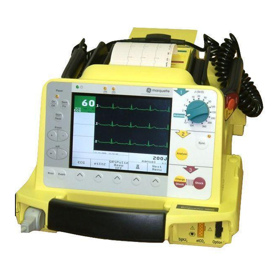
Page 6: Controls And Indicators
Controls and Indicators 2 Controls and Indicators The Device 20 30 Pacer Autoseq Start Pause P/min Sync — Analyse — Print Event Figure 2-1. Controls and indicators of the Marquette Responder® 3000 Marquette Responder® 3000 227 490 02-C... - Page 7 Controls and Indicators Connector for exchange of the defibrillation 18 Button to start and stop the recorder electrodes (switch off the device before ex- 19 Button to change the pacer output (current) changing the electrodes!) 20 Button to change the pacer rate APEX paddle 21 Button to pause the pacer (without changing Infrared interface...
- Page 8 Defibrillation Electrodes Defibrillation Electrodes Hard Paddles Hard paddles are the electrodes commonly used for external, transchest defibrillation. There is a special Apex paddle and a Sternum paddle. For delivery of the defibrillation shock, the paddles are placed directly on the body surface. Before use, however, an ample amount of electrode gel must be spread onto the paddles.
-
Page 9: Putting The Device Into Operation And Performance Check
Putting the Device Into Operation and Performance Check 3 Putting the Device into Operation and Performance Check Safety information Warning Danger Shock Hazard — Observe the following warnings. Explosion Hazard – The device is not designed for Otherwise the lives of the patient, the user and use in areas of medically used rooms where an bystanders are in danger. - Page 10 Putting the Device Into Operation and Performance Check Electrically conductive contact with parts The mains plug must be connected to an connected to the heart (pressure transducers, appropriate power supply with a non-fused metal tube connections and cocks, guide earthed wire. If these requirements cannot be wires, electrode catheters and the metal parts guaranteed, connect the device to the ambu- of syringes) must be avoided at all cost.
- Page 11 Putting the Device Into Operation and Performance Check Literature Warning Equipment Failure — Magnetic and electrical Medical Device Directive of August 2, 1994 fields are capable of interfering with the EN 60601-1: 1990 + A 1: 1993 + A 2: 1995 proper performance of the device.
- Page 12 Putting the Device Into Operation and Performance Check Power Supply The defibrillator can be powered − from the power line (requires AC power adapter, P/N 205 108 01, Figure 3-1), − from the ambulance power supply system (requires vehicle mounting unit, P/N 202 317 01), −...
- Page 13 Putting the Device Into Operation and Performance Check The Standard Screen Display This is the information presented on the standard screen display: Electrode − windows for heart / pulse rate, SpO and etCO Paddle 160 / 40 readings including the limit values a, b SpO2 parameter −...
- Page 14 Putting the Device Into Operation and Performance Check Display Flip The screen display can be rotated 180° to adapt it ↓ to the operating position of the defibrillator. The QRSPulse SpO2 Next display can be flipped permanently from the setup Tone etCO2 Menu...
- Page 15 Putting the Device Into Operation and Performance Check Parameter Comment Factory Options User Setup Defaults ALARM LIMITS HR Limit 40/160 OFF, 15 to 300 increments of 5 Limit ---/90 OFF, 60 to 99 etCO Limit ---/20 OFF, 5 to 76 increments of 1 Print on Alarm autom.
- Page 16 Putting the Device Into Operation and Performance Test Performance Check A performance check must be carried out before Electrode each use. Paddle 160 / 40 The check includes: − a visual inspection of the device, the cables and the electrodes for signs of mechanical damage, −...
- Page 17 Putting the Device Into Operation and Performance Test How to toggle the defibrillator from semiautomatic to manual operation Depending on their setup, semiautomatic defibril- lators can be switched to manual control. The Sync defibrillator can be set up for four different modes of operation: Analyse −...
-
Page 18: Manual Defibrillation
Manual Defibrillation / Non-Synchronized Defibrillation 4 Manual Defibrillation 4.1 Defibrillator Application Guidelines Observe the following guidelines to ensure successful and safe defibrillation. Otherwise the lives of the patient, the user and bystanders are in danger. Warning Pacemaker Patients — Defibrillating a patient with an implanted pacemaker is likely to im- Defibrillating a patient with normal heart pair the pacemaker function or cause damage... -
Page 19: Non-Synchronized Defibrillation
Manual Defibrillation / Non-Synchronized Defibrillation 4.2 Non-Synchronized Defibrilla- tion Using Paddles • Remove the paddles from their compartments as shown in Figure 4-1. • Carefully dry the paddles and the handles in particular, if they are wet. • Apply an ample amount of electrode cream to Figure 4-1. - Page 20 Manual Defibrillation / Non-synchronized Defibrillation • Initiate energy storage with the button on the APEX paddle (a). When the selected energy is stored, SHOCK CHARGE SHOCK − the device emits an audio signal STERNUM APEX − the message "Energy available" appears, −...
- Page 21 Manual Defibrillation / Non-Synchronized Defibrillation Shock Counter Defibrillation of Children The number of delivered shocks is indicated below Warning the energy value. Damage to Myocardium — Please note that chil- This counter is reset to 0 when you set the energy dren require less energy for successful ventricular selector to defibrillation than adults.
- Page 22 Manual Defibrillation / Non-synchronized Defibrillation Using Disposable Defibrillation Pads − Use pads before their expiration date. − Do not reuse the pads. Danger − A pair of pads may remain attached to the Shock Hazard — For defibrillation with dispos- patient for up to 24 hours and withstands up to able adhesive electrodes, the paddles including 50 shocks of 360 J each.
- Page 23 Manual Defibrillation / Non-Synchronized Defibrillation • Before delivering the shock, check that the pads Warning are firmly seated. Risk of Skin Burns / Equipment Damage — Do not • Defibrillate the patient as described for attach the pads over defibrillation with paddles (page 19). sternum or clavicle Be sure to charge the defibrillator with nipples...
- Page 24 Manual Defibrillation / Non-synchronized Defibrillation Using Internal Defibrillation Elec- trodes Warning Note Shock Hazard – Always switch off the device If you are using internal electrodes with the before exchanging the defibrillation electrodes Marquette Responder® 3000, defibrillator charg- and internal spoons. ing must be initiated with button and the shock is delivered by simultaneously pressing...
- Page 25 Manual Defibrillation / Non-Synchronized Defibrillation Defibrillating the Patient With internal electrodes, it is not possible to select a value above 50 Joules, because higher energies may damage the myocardium. When you set the Sync energy selector to a value above 50 Joules, you will be alerted by a message and defibrillator Analyse charging will not proceed.
-
Page 26: Synchronized Defibrillation (Cardioversion)
Manual Defibrillation / Synchronized Defibrillation 4.3 Synchronized Defibrillation (Cardioversion) Some Basic Facts For synchronized defibrillation (cardioversion) the Warning defibrillation shock is delivered in synchronization with the heart action, as the heart is still working. False Triggering — Do not use a pacemaker ECG As a prerequisite, the patient's ECG signal must be for triggering, because the trigger pulses derived supplied to the defibrillator. - Page 27 Manual Defibrillation / Synchronized Defibrillation ECG Acquisition via Separate ECG Electrodes and Patient Cable Use only silver/silver-chloride electrodes to acquire the ECG signal. These electrodes prevent polarization voltages which may be caused by the yellow defibrillation shock, resulting in an ECG trace on the monitor screen or recording that simulates cardiac arrest.
- Page 28 Manual Defibrillation / Synchronized Defibrillation ECG Acquisition via Defibrillation Pads • Apply the defibrillation pads as shown in Figure 4-16. STERNUM • Turn on the device (energy selector to electrode and connector The ECG signal is now acquired via the pads and will automatically be displayed in channel 1 (unless a patient cable is connected).
- Page 29 Manual Defibrillation / Synchronized Defibrillation Performing Cardioversion • Check the ECG. The ECG signal must be interference-free and 160 / 40 have an adequate amplitude. Follow these steps to select another lead (only possible when the ECG is acquired via separate ECG electrodes) or to change the signal size: −...
-
Page 30: Semiautomatic Defibrillation
Semiautomatic Defibrillation 5 Semiautomatic Defibrillation Safety Information In addition to the defibrillation guidelines set forth in chapter 4, please observe the following information: Failure to do so may compromise the success of the defibrillation or endanger the patient's life. Warning Caution Semiautomatic defibrillation is only permitted When used on pacemaker patients, the device... - Page 31 Semiautomatic Defibrillation Some Basic Facts On the control panel of the semiautomatic If you do not set the energy selector to "Autoseq", defibrillator there is one additional button: Analyse an error message will be displayed. The message is cleared when In the semiautomatic mode, an arrhythmia −...
- Page 32 Semiautomatic Defibrillation Defibrillating the Patient in the Semiautomatic Mode We recommend to defibrillate the patient with disposable adhesive pads in this mode. Thus, you only have to apply two electrodes, because the ECG signal can also be acquired via the pads. Pads 160 / 40 If you are using separate ECG electrodes, please...
- Page 33 Semiautomatic Defibrillation • Do not touch the patient any more and warn all those present. Pads • 160 / 40 Press Analyse to initiate ECG analysis. You will see the message "ANALYZING Do not touch patient" (Figure 5-2). If the analysis algorithm detects ventricular flutter (>...
- Page 34 Semiautomatic Defibrillation Note Note Immediately after selecting "Autoseq", the If the analysis algorithm does not recommend a charge sequence restarts with the lowest en- defibrillation, even though the patient is suspected ergy level. There is no time limit for the Auto- to suffer from a shockable arrhythmia, press Analyse sequence shocks.
- Page 35 Semiautomatic Defibrillation ECG Acquisition via Separate ECG Electrodes Use only silver/silver-chloride electrodes to acquire the ECG signal. These electrodes prevent polarization voltages which may be caused by the yellow defibrillation shock, resulting in an ECG trace on the monitor screen or recording that simulates cardiac arrest.
-
Page 36: Pacemaker
Pacemaker 6 Pacemaker Some Basic Facts Application and Functional Description Turning the pacemaker ON: The transcutaneous pacemaker of the Marquette 1. Apply ECG electrodes to patient. Responder® 3000 is used for external (transchest) 2. Connect ECG electrodes to the device. cardiac stimulation in emergencies. - Page 37 Pacemaker Guidelines for the Application of External Pacemakers • All electrical devices that deliver energy to Check the defibrillator performance before patients in any form or have an electrically using the pacemaker on a patient. • conductive connection to the patient present a The pulse current output of the pacemaker is potential hazard.
- Page 38 Pacemaker Demand Pacing Caution: The pacer pulses are delivered via the adhesive defibrillation electrodes which must be Warning applied as described in chapter 4. Shock Hazard — During pacing set the energy Separate electrodes must be applied for acquisition selector to to prevent that a defibrillation of the ECG signal (chapter 7).
- Page 39 Pacemaker • Select a low pacer current output with — e.g. 20 mA (19, Figure 6-1). 160 / 40 • P/min Select the required pacer rate with — • Now increase the pacer current output slowly with until the heart reliably responds to —...
- Page 40 Pacemaker Fixed-Rate Pacing Caution: The pacer pulses are delivered via the adhesive defibrillation electrodes which must be Note applied as described in chapter 4. The default pacer rate can be configured. Separate electrodes must be applied for acquisition If a defibrillation shock is triggered during of the ECG signal (chapter 7).
-
Page 41: Displaying And Monitoring The Ecg
Displaying and Monitoring the ECG 7 Displaying and Monitoring the yellow Displaying the ECG For a quick diagnosis of the ECG, you can use the defibrillation electrodes (paddles) to acquire the ECG. white For in-depth examinations and heart rate monitor- ing, the ECG signal should be acquired via separate ECG electrodes. - Page 42 Displaying and Monitoring the ECG The HR window is green, indicating that no electrode problem was detected and the heart rate is 160 / 40 within the alarm limits. If an electrode problem exists, the color changes from green to blue (in addition, an audio signal sounds after 30 seconds - configurable).
- Page 43 Displaying and Monitoring the ECG Activating and Deactivating Filters Activating muscle and AC line filters makes the displayed ECG insensitive to AC interference and muscle tremor. However, the filters alter the ECG signal, and a filtered signal is not suitable for diagnosis (displayed or printed ECG).
- Page 44 Displaying and Monitoring the ECG Monitoring Heart Rate The default heart limits are 40 and 160 bpm and Warning the audio alarm is disabled (factory default No Asystole Alarm — The defibrillator gives settings, bell symbol in button F4 is crossed out asystole alarm only when the heart rate falls ).
- Page 45 Displaying and Monitoring the ECG Monitoring Arrhythmia Monitoring Pacemaker Patients The device allows you to continuously monitor the When monitoring the heart rate of pacemaker ECG for arrhythmias (see Appendix "The patients, only the patient's QRS complexes must be Arrhythmia Detection Program"). counted and pacer pulses must be rejected.
-
Page 46: 12-Lead Ecg Analysis Program (12Sl )
12-Lead ECG Analysis Program (12SL 8 12-Lead ECG Analysis Program (12SL Introduction Overview The first human electrocardiogram was taken over A program's accuracy is directly dependent upon a hundred years ago, and computerized electrocar- the quality of the signal it acquires. In 1979, diography has been in existence since the late Marquette Hellige introduced an electrocardio- 1950s. - Page 47 12-Lead ECG Analysis Program (12SL Median Beat, Signal Averaging Measurements, Onsets and Offsets All ECG computer programs are composed of two Computer measurement for features within the parts: one which measures the waveforms and one QRS complex are very susceptible to artifact. To which does the analysis based upon those remove artifact, filtering may be used.
- Page 48 12-Lead ECG Analysis Program (12SL 12SL Measurement For measurement and interpretation 12 seconds of ECG data are saved. After the analysis, the interpretation is presented on the monitor screen. 160 / 40 You can also print the ECG including the measurement results and the interpretation.
-
Page 49: Pulse Oximetry (Spo )
Pulse Oximetry 9 Pulse Oximetry (SpO Some Basic Facts measurement is used to determine the percentage of functional hemoglobin saturated 160 / 40 with oxygen in the patient's arterial blood. Alarm limits can be set for monitoring of the SpO value. - Page 50 Pulse Oximetry C-Lock ECG Synchronization Application Tips The C-Lock ECG synchronization feature enables General Tips the device to use an ECG signal as a reference − Use only the probes listed in chapter 20 "Order point for identifying the pulse and synchronizing Information".
- Page 51 Pulse Oximetry To minimize motion artifact When monitoring SpO during electrosurgical intervention, take care that − take care to provide an ECG of good quality − the device is powered from the internal battery (C-Lock ECG synchronization), or from a different power circuit than the −...
- Page 52 Pulse Oximetry Measuring and Monitoring Oxygen Saturation • Apply the probe as described in the user instructions supplied with the probe and con- 160 / 40 nect it to the defibrillator (blue connector). The SpO measurement begins as soon as the SpO2 sensor is connected.
- Page 53 Pulse Oximetry Selecting the HR Source The device can be set up to derive the heart rate from the SpO signal. The heart rate source is selected with F4 in the SpO menu (Figure 9-3). Adjusting Alarm Limits The alarm limits can be modified permanently Alarm High Alarm...
-
Page 54: Capnometry (Etco )
Capnometry (etCO 10 Capnometry (etCO Some Basic Facts The etCO sensor uses the infrared spectroscopy method. The sensor consists of the sensor itself b (including the IR source and the photodetector) and ADAPTER the airway adapter a which is attached to the sensor. OPER/ALARM The entire sensor is placed in the patient's airway (expired air) between the respirator and the tube. - Page 55 Capnometry (etCO Safety Information Warning The sensor may give lower readings when Observe the following information to prevent used in a low pressure environment (do not erroneous CO measurements. Inappropriate use in airplane). therapeutic measures based on erroneous readings Do not allow condensation to develop in the may cause severe damage or the patient's death.
- Page 56 Capnometry (etCO Measuring and Monitoring etCO • Obtain a new airway adapter and check that the windows are intact and clean. • Attach the airway adapter to the sensor (the triangles on the airway adapter and on the sensor must be in alignment - Figure 10-3). •...
- Page 57 Capnometry (etCO altitude error Displaying the Capnogram 0.0% 1000 1500 2000 2500 3000 3500 4000 4500 5000 -5.0% The capnogram can be displayed in channel 3 with -10.0% a sweep speed of 6.25 mm/s (but it is printed with -15.0% a speed of 25 mm/s).
-
Page 58: Memories Of The Marquette Responder® 3000
Memories of the Marquette Responder® 3000 11 Memories of the Marquette Responder® 3000 The Marquette Responder® 3000 has 4 different Note memories: Switching off the defibrillator does not automati- − an event memory cally clear the memories. Therefore, the memories could contain data from different patients. - Page 59 Memories of the Marquette Responder® 3000 ECG Memory The defibrillator saves the most recent 180 minutes of full disclosure ECG data displayed in channel 1 and acquired while the defibrillator was on. When the memory is full, the information is automatically updated, so that the most recent 180 minutes are always available.
- Page 60 Memories of the Marquette Responder® 3000 Trend Memory In the trend memory the device collects the HR, and etCO values of the past 4 hours. The Note trend data, too, are automatically updated. The Power on and off are marked with a vertical line stored data can be printed out in the form of in the graphic trends.
-
Page 61: Recording
Recording 12 Recording Initiating a Recording The recorder can be started and stopped with Print With the factory settings unchanged, the recorder will print a 14-second strip of the displayed ECG and a status report when you press . Then the recorder Print stops. - Page 62 Recording Loading Chart Paper To prevent damage to the printhead, use the original HELLIGE CONTRAST paper only (P/N 226 168 02). • Open the paper compartment door all the way (Figure 12-2). • Remove the spindle with the sleeve of the previous paper roll.
-
Page 63: Defibrillator Setup
Defibrillator Setup 13 Defibrillator Setup The defibrillator has a setup menu which allows you to adjust many of the device functions to your preferred settings and to save these as defaults 160 / 40 which are activated each time the defibrillator is Setup switched on. - Page 64 Defibrillator Setup Alarm Limits Autosequence selection of the HR, SpO and etCO alarm limits entry of the energy levels for the 1st, 2nd and 3rd defibrillation shock Print on Alarm Pacemaker recorder starts upon violation of an alarm limit default pacer rate Lead Fail Alarm Date/Time audio signal when electrode is off the patient...
- Page 65 Defibrillator Setup AC Line Filter Changing the Password • eliminates AC interference (50 Hz = filter enabled, Using F1 or F2 , position the bar ↓ ↑ 50 Hz AC line frequency in Europe; 60 Hz = filter cursor on PASSWORD and confirm the selec- enabled, 60 Hz AC line frequency in the USA) tion with F3 ENTER...
- Page 66 Defibrillator Setup Event Texts Options Entry of up to 8 event texts (max. 8 characters For activation of optional program modules each); these texts are assigned to the softkeys F1 (Figure 13-6). to F4 (chapter 3, section "Event Button") The defibrillator serial number has already been Using ←...
-
Page 67: Battery Power Operation
Battery Power Operation 14 Battery Power Operation Battery Charging (ambulance power supply, power line) The batteries recharge when you − place the defibrillator in the vehicle mounting unit / wall mount unit or − connect the defibrillator to the power line (units with AC power adapter). - Page 68 Battery Power Operation Information on Battery Power Operation Rechargeable batteries require special maintenance and continued checks to assure they function in Electrode emergency situations. It is normal for batteries of 160 / 40 this type to self-discharge, even when the device is switched off.
- Page 69 Battery Power Operation Battery Maintenance Program The batteries should be reconditioned once a month with the battery maintenance program. As the battery will be discharged in the course of the maintenance program, a second battery is required to ensure that the defibrillator is ready for use. The maintenance program can be activated with the defibrillator connected to the power line or to the Figure 14-4.
-
Page 70: Test Discharge
Test Discharge 15 Test Discharge On defibrillators set up for semiautomatic defibrillation, a test discharge can be delivered Sync only − when you activate the manual mode (next Analyse section) or − use a simulator. How to toggle the defibrillator from semiauto- matic to manual operation •... - Page 71 Test Discharge Electrode Test Discharge (manual mode) 160 / 40 The correct release of the defibrillation shock can be checked by means of a test discharge. For this test, the stored energy is discharged into the device via two contacts in the paddle compartments. When adhesive pads are connected to the defibrillator, the test discharge is only possible with a suitable simulator;...
- Page 72 Test Discharge • Now trigger the shock within 30 seconds. To do so, simultaneously press the two buttons on the paddles (or on the control panel, Sync when using adhesive pads) (Figure 15-7). Analyse After the shock release, the audio signal stops and the delivered energy is displayed for about 6 seconds.
-
Page 73: Operation In The Vehicle Mounting Unit, Mounting The Ac Power Adapter
Operation in the Vehicle Mounting Unit, Mounting the AC Power Adapter 16 Operation in the Vehicle Mounting Unit, Mounting the AC Power Adapter Operating the Defibrillator in the Vehicle Mounting the AC Power Adapter Mounting Unit The AC power adapter is screwed to the rear of the ®... -
Page 74: Error And System Messages
Error and System Message 17 Error and System Messages Message Effect Explanation Remedy D-RAM Error device defect, device notify service cannot be used S-RAM Error device defect, device notify service cannot be used FLASH Error device defect, device notify service cannot be used EEPROM Error restricted use for... -
Page 75: Cleaning, Maintenance
Cleaning, Maintenance 18 Cleaning, Maintenance Cleaning, Disinfection and Steriliza- tion Electrodes, Device • Discard all disposable items immediately after use to prevent that they are reused. Danger • The paddles and their leads can be cleaned and Shock Hazard — Before cleaning the device, disinfected by wiping them down with a gaze disconnect it from the power line. - Page 76 Cleaning, Maintenance Inserting the Spoon Electrode • Screw the counter nut 2 (Figure 18-1) onto the electrode as far as it will go. • Screw the contact paddle 1 into the handle as far as it will go, then bring it into the appropri- ate position.
- Page 77 Cleaning, Maintenance Maintenance Technical Inspections Checks before each use • For safety, the devices require regular mainte- Before each use, visually inspect the device, the nance. To ensure functional and operational safety leads and electrodes for signs of mechanical of the Marquette Responder® 3000, Technical damage.
-
Page 78: Technical Specifications
Technical Specifications 19 Technical Specifications • Operating Modes capacitor charging time for energy setting of 360 J: − non-synchronized (defibrillation on demand) − on line power and when inserted in vehicle − synchronized (cardioversion) mounting unit typically 9 s − semiautomatic (in the presence of shockable −... - Page 79 Technical Specifications Pulse Output Synchronization isolated, no conductive connection with enclosure, with ECG signal of either polarity: open-circuit and short-circuit-proof as required by • minimum ECG amplitude for reliable triggering AAMI DF-2: approx. 0.50 mV and QRS width of 80 ms •...
- Page 80 Technical Specifications ECG Signal Input Via Patient Cable Signal Transmission automatic switching to ECG electrodes, if they are signal input --> amplification --> signal sampling - applied; -> AD conversion --> digital processing --> differential input, symmetrically referred to N, display and recorder •...
- Page 81 Technical Specifications Signal Display Alarm System active backlit VGA color LCD, 3-channel erase electronic release of alarm bar display, alphanumeric indication of alarms, • when the heart rate violates one of the set alarm gain, lead, QRS indicator, alarm limits, heart rate, limits (after condition exists for 10 seconds): energy and function key labels audio signal sounds (can be disabled), message...
- Page 82 Technical Specifications After recording the ECG, the recorder will print an intervention report (name, date of birth, user, • saturation: 0 to 100% in increments of 1 % comments – entered by the user - defibrillation • mode, selected and delivered energy, number of rate: 0 to 250 P/min in increments of 1 P/min •...
- Page 83 Technical Specifications Power supply Type of Protection protected against splashing water; Marquette Battery Responder: IPX 4 (batteries inserted, cables power supply from 1 or 2 exchangeable NiCd connected) batteries AC power adapter: IPX 1 • Environment rated voltage 12 V •...
-
Page 84: Order Information
Order Information 20 Order Information Accessories Subject to change. Always refer to latest list of accessories. 412931-002 Patient trunk cable, 5-lead cable, 101 164 01 Marquette Responder® 3000, 3.6 m, IEC, MultiLink basic system, manual operation, recorder 412931-001 Patient trunk cable, 5-lead cable, 3.6 m, AHA, MultiLink 101 264 02 Marquette Responder®... - Page 85 Order Information Consumables Internal defibrillation 226 168 02 Chart paper, 90 mm, 10 rolls 217 308 01 Pair of defib electrodes for internal defibrillation (w/o. 217 123 01 Adhesive rings for electrode contact insert) 217 320 01, 500/cs. 384 013 19 Contact inserts (2), internal, for 927 223 00 Adhesive rings for electrode...
- Page 86 Order Information Pacemaker 919 202 94 Disposable defibrillation pad, rectangular, for adults (1 pair) 919 202 95 Disposable defibrillation pad, rectangular, for children (1 pair) 223 383 01 Connecting cable for defibrilla- tion electrodes 919 202 94/95 Miscellaneous 227 490 02 Operator's Manual 931 099 56 Carrying bag, no labeling...
-
Page 87: Appendix
The Arrhythmia Detection Program Appendix The Arrhythmia Detection Program Overview The arrhythmia detection program used in the The consensus opinion published by AAMI***(TIR #2-1987), is that specificity should Marquette Responder® Series defibrillators was developed by Marquette Medical Systems, Inc. be as high as possible, even at the sacrifice of some sensitivity. -
Page 88: Ec Declaration Of Conformity
EC Declaration of Conformity Marquette Responder® 3000 227 490 02-C... -
Page 89: Index
Index Index 12SL ECG analysis program ECG acquisition via separate ECG electrodes ECG display ECG memory ECG signal size Electrode for internal defibrillation AC line filter EMC requirements AC power adapter, mounting Error messages Accessories Event memory Adhesive electrode, defibrillation, pacing Event texts Airway adapter Events, primary... - Page 90 Index Semiautomatic defibrillation 30, 31 Setup Options Setup menu Order information Shock counter Specifications SpO2 measurement measurement, begin Spoon electrode, insertion 24, 76 Pacemaker Sterilization Pacemaker patients Switching from semiautomatic to manual defibrillation Pacemaker, guidelines for application 17, 70 Pacemaker, turn off Symbols used on the device, explanation Packaging material, disposal Synchronization pulses...