
Related Manuals for GE MAC 800


Summary of Contents for GE MAC 800
- Page 1 GE Healthcare MAC™ 800 Resting ECG Analysis System Operator's Manual Software Version 2.0.x 2060026-001 Revision C MAC 800 Resting ECG Analysis System English © 2012 General Electric Company. All Rights Reserved.
- Page 2 Archivist, CardioSoft, CASE, Hookup Advisor, MAC, Mactrode, Multi-Link, MUSE, SilverTRACE, and 12SL are trademarks owned by GE Medical Systems Information Technologies, Inc., a General Electric Company going to market as GE Healthcare. All other trademarks contained herein are the property of their respective owners.
-
Page 3: Table Of Contents
Hardware Supplied by GE Healthcare ........ - Page 4 Leadwire Adapters ................. . . 32 Carrying Handle .
- Page 5 Hookup Advisor Module ................61 Special Consideraitons................62 Recording ECGs of Pacemaker Patients ............62 Recording ECGs During Defibrillation .
- Page 6 Setup Functions ..................87 Basic Setup ................... . 87 Resting ECG Setup.
- Page 7 Creating Barcodes Setting Up the Patient Data Scheme............135 Configuring the Barcode Reader............. 135 Configuring the Barcode Reader Manually ........... . 136 Configuring the Barcode Reader Automatically .
- Page 8 MAC™ 800 2060026-001C...
-
Page 9: Introduction
Introduction This document describes the MAC™800 Resting ECG Analysis System, also referred to as “the system” or “the device”. This chapter provides general information required for the proper use of the system and the manual. Familiarize yourself with this information before using the system. Indications for Use The MAC™... -
Page 10: Prescription Device Statement
Introduction Prescription Device Statement CAUTION: United States federal law restricts this device to sale by or on the order of a physician. Regulatory and Safety Information This section provides information about the safe use and regulatory compliance of this system. Familiarize yourself with this information, and read and understand all instructions before attempting to use this system. - Page 11 Patient signal inputs labeled with the CF symbol with paddles are protected against damage resulting from defibrillation voltages. To ensure proper defibrillator protection, use only GE Healthcare-recommended cables and leadwires. Proper placement of defibrillator paddles in relation to the electrodes is required to ensure successful defibrillation.
- Page 12 (or back). Refer servicing to qualified personnel. WARNING: BURN PROTECTION — To ensure defibrillator protection and protection against high-frequency burns, use only GE Healthcare-recommended cables and leadwires. Otherwise, serious injury could result. WARNING: HIGH-FREQUENCY PRECAUTIONS — Do not use the device with high-frequency surgical devices.
-
Page 13: Rf Caution
If you have questions concerning disposal of the product, please contact GE Healthcare or its representatives. -
Page 14: Emi/Emc Requirements
EMI/EMC Requirements The device or system is labeled under the original equipment manufacturers label (for example, USA FCC 47CFR15, CE EU EMC 2004/108/EC), and deemed sufficient by GE Healthcare to be in compliance with EN/IEC 60601-1-2 when used according to the device or system’s intended use. -
Page 15: Nrtl Certification Mark
If you have questions in this matter, please contact GE Healthcare or its representatives. Legal Notice Our equipment contains several fields which can be filled in before performing an ECG. - Page 16 Modem Requirements Modems supplied by GE Healthcare are designed to comply with applicable country requirements (such as USA FCC 47CFR68, CE EU R&TTE 1999/5/EC). Refer to the device for a registration number and ringer equivalence number (REN). The modem is designed for use on standard device telephone lines.
-
Page 17: Parts And Accessories Information
60601-1 and/or 60601-1-1 standard(s). Responsibility of the Manufacturer GE Healthcare is responsible for the effects of safety, reliability, and performance on hardware supplied by GE Healthcare only if the following conditions are met: • Assembly operations, extensions, readjustments, modifications, or repairs are carried out by persons authorized by GE Healthcare. -
Page 18: Symbols
Introduction Symbols The following symbols may appear on the device or its packaging. Familiarity with these symbols assists in the safe use and disposal of the equipment. For equipment symbols not shown, refer to the original equipment manufacturers (OEM) manuals. Defibrillation-proof type CF equipment. - Page 19 Introduction Catalogue (part) number. Serial number. Date of manufacture. Manufacturer address. Recyclable. Atmospheric limits. Temperature limits. Humidity limits. Keep dry. Fragile. Alternating current. Battery symbol. The flashing amber LED next to this symbol indicates you must connect the system to AC power to re-charge the battery.
- Page 20 Introduction Environment-friendly Use Period per Chinese standard SJ/T11363-2006 (China specific). Secure Digital (SD) Card. Batch or lot number. Authorized European Representative. CCC Mark - China Compulsory Certification mark TÜV Rheinland NRTL Certification Mark. China Metrology Certification. Indicates conformity with applicable European directives. MAC™...
-
Page 21: Training
If you have not received training on the use of the system, you should request training assistance from GE Healthcare. To see available training, go to the GE Healthcare training Web site (http://www.gehealthcare.com/usen/education/index.html). Under the Technical Service Education section, select Diagnostic Cardiology. -
Page 22: Equipment Identification
Introduction Equipment Identification Every GE Healthcare device has a product label that identifies the product name, part number, manufacturing information, and unique serial number. This information is required when contacting GE Healthcare for support. Product Label The product label is laid out in the following format. Depending on the product, the label may vary slightly in format, but it contains the same information. -
Page 23: Product Codes
• On the product label provided with the application CD. Service Information This section provides information pertaining to the maintenance and servicing of the system. Familiarize yourself with this information before requesting service from GE Healthcare or its authorized representatives. Service Requirements... -
Page 24: Hardware Supplied By Ge Healthcare
Any unauthorized attempt to repair equipment under warranty voids that warranty. It is the user's responsibility to report the need for service to GE Healthcare or to one of their authorized agents. Additional Assistance GE Healthcare maintains a trained staff of application and technical experts to answer questions and respond to issues and problems that may arise during the installation, maintenance, and use of this system. -
Page 25: Related Documents
Introduction Convention Description <space> Indicates that you must press the spacebar. When instructions are given for typing a precise text string with one or more spaces, the point where you must press the spacebar is indicated as: <space>. This ensures that the correct number of spaces are inserted in the correct positions within the literal text string. - Page 26 Introduction MAC™ 800 2060026-001C...
-
Page 27: Equipment Overview
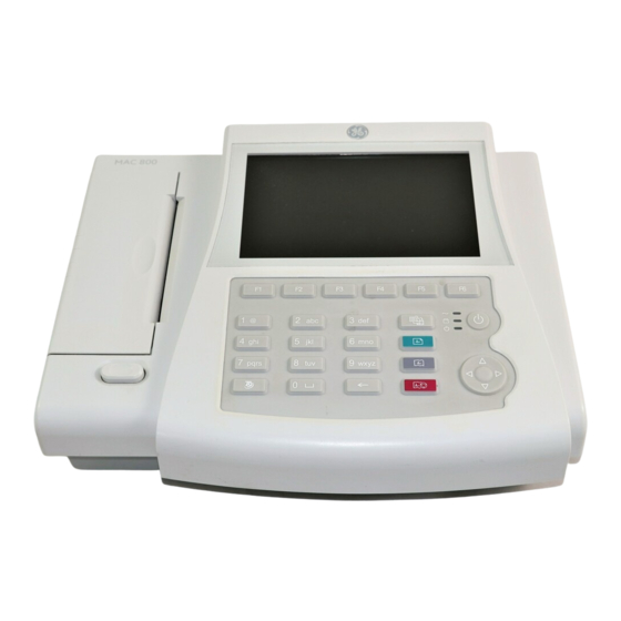
Equipment Overview Equipment Description Front View Item Name Description Display Presents waveform and text data. Power LED Indicates the device is plugged in and receiving power. 2060026-001C MAC™ 800... -
Page 28: Side View
Equipment Overview Item Name Description Battery LED Indicates various battery states: • Solid amber light indicates the battery is charging. • Flashing amber light indicates the battery is low. • Off indicates the battery is neither charging nor low. Operating LED Indicates the system is running. -
Page 29: Rear View
Equipment Overview Rear View Item Name Description Modem Port RJ11 connector from the optional internal modem to an analog phone line. LAN connection RJ45 network connector. The LEDs indicate LAN status. • The steady green LED to the right of this port indicates a good ethernet connection. -
Page 30: Bottom View
Equipment Overview Bottom View Item Name Description Battery Rechargeable lithium-ion battery. Carrying handle Handle for carrying the device. Keyboard Layout Your keyboard may differ slightly from the following illustration. Item Name Description Function Keys (F1 through F6) Selects menu options on the screen. Refer to “Selecting Menu Options”... -
Page 31: Acquisition Modules
Equipment Overview Item Name Description ECG key Acquires a resting ECG and prints a 10-second report in Arrhythmia mode. Trimpad The arrows move the cursor left, right, up, or down to highlight a menu or screen item. Pressing the center button selects the highlighted item. -
Page 32: Leadwire Adapters
Equipment Overview CAUTION: PROPER LEADWIRE CONNECTION — Improper connection of the leadwires can cause inaccuracies in the ECG. Trace each individual leadwire from its acquisition cable label to the colored connector and then to the proper electrode to ensure that it is matched to the correct label location. -
Page 33: Carrying Handle
Equipment Overview Carrying Handle When you need to move the system, you can use the carrying handle for convenience. Observe the following steps to use the handle correctly. Setting Up the Equipment Setting up this system consists of the following steps: Inserting the battery. -
Page 34: Inserting The Battery
Equipment Overview Inserting the Battery This system is shipped with a lithium-ion battery that charges when it is inserted into the system connected to AC power. Gently turn over the device and find the empty battery compartment. Insert the battery as shown in the following illustration. NOTE: The battery charges when it is inserted into a system that is connected to AC power. - Page 35 Equipment Overview Use the following instructions to connect the device to an AC power outlet. Connect the female end of the device’s power cord to the AC power connector on the rear of the device. (1) Plug the male end of the device’s power cord into an AC outlet. (2) Check the Power LED to make sure the device is receiving power from the AC outlet.
-
Page 36: Connecting Leadwires
Equipment Overview Connecting Leadwires Use the following instructions to connect your leadwires and acquisition module to the device. WARNING: ELECTRICAL SHOCK — Injury can result from connecting the patient cables directly to an AC power outlet. Connect patient cables only to the ECG Signal Input Connector on the device. Assemble the leadwires and adapters. -
Page 37: Connecting The Barcode Reader
Equipment Overview To use a third-party card reader with the system, connect it to the device’s USB port. Refer to the magnetic card reader’s documentation for additional information. NOTE: Do not connect a magnetic card reader if the barcode reader option (BCRD) is enabled. -
Page 38: Turning On The System
Equipment Overview Refer to the printer’s documentation for setup information. NOTE: If connection problems occur, the printer is connected to the device, or the connected network printer is not compliant with PJL language. The following error is displayed: Printer Connection Failed. NOTE: If you are using a network printer, save all reports before printing. -
Page 39: Using The Keyboard
Equipment Overview • Main Screen • A window prompting you to enter User ID and Password. NOTE: The password window opens only if the High Security Mode option is selected in Basic Setup. You can press F1 (STAT ECG) to begin taking an ECG without logging in to the system. - Page 40 Equipment Overview Navigating Data Entry Windows Use the trimpad to navigate through data entry windows. Press the arrows to move the cursor left, right, up, and down through the fields. Press the center button to select the current field. If the field is associated with a list of valid values, that list is displayed.
-
Page 41: Preparing The Patient
Look at the lead-check screen for indication of lead problems. NOTE: Use only electrodes and contact agents recommended by GE Healthcare. The signal quality on the lead-check screen is not indicated until the RA/R electrode is applied. If RA/R becomes disconnected, the system will report that all electrodes are off the patient. -
Page 42: Electrode Placement
Preparing the Patient Electrode Placement This section describes various methods for placing electrodes for resting ECGs. CAUTION: PROPER LEADWIRE CONNECTION — Improper connection will cause inaccuracies in the ECG. Trace each individual leadwire from its acquisition module label to the colored connector and then to the proper electrode to ensure that it is matched to the correct label location. - Page 43 Preparing the Patient Standard 15 Lead Placement AHA Label IEC Label Description V1 red C1 red Fourth intercostal space at the right sternal border V2 yellow C2 yellow Fourth intercostal space at the left sternal border V3 green C3 green Midway between location 2 and 4 V4 blue C4 brown...
- Page 44 Preparing the Patient Frank X, Y, Z Placement AHA Label IEC Label Description LA black L yellow Just below the clavicle of the left arm E orange E light blue Mid-sternum on the same horizontal level as 3 and 4 V4 blue C4 brown Mid-clavicular line in the fifth intercostal space...
- Page 45 Preparing the Patient NEHB Placement AHA Label IEC Label Description A1 orange Nst white Attachment point of the second rib to the right sternal edge A2 orange Nax white Fifth intercostal space on the left posterior axillary line (Same position as V8 or C8) V4 blue Nap white Mid-clavicular line in the fifth intercostal space (Same...
- Page 46 Preparing the Patient Pediatric Placement AHA Label IEC Label Description V1 red C1 red Fourth intercostal space at the right sternal border V2 yellow C2 yellow Fourth intercostal space at the left sternal border V3 green C3 green Midway between location 2 and 4 V4 blue C4 brown Mid-clavicular line in the fifth intercostal space...
-
Page 47: Entering Patient Information
Entering Patient Information Entering Patient Information Manually Patient information should be entered for each new patient from whom readings are taken. Use the following procedure to enter the information if you do not use a barcode reader or if you want to modify or add to the patient data entered with a barcode reader. -
Page 48: Entering Patient Information With A Barcode Reader
Entering Patient Information Use the F3 and F4 keys to move backward and forward through the patient data windows. The F4 key moves forward one screen. The F3 key moves backward one screen. NOTE: If the CTDG (Clinical Trial Data Guard) option is activated, you enter clinical trial data on the last window. -
Page 49: Entering Patient Information With A Magnetic Card Reader
Entering Patient Information Entering Patient Information with a Magnetic Card Reader Using a magnetic card reader can simplify the entry of patient information and reduce the introduction of errors. When you swipe a patient’s magnetic card, it retrieves the patient information encoded in the card’s magnetic strip. You can then verify or modify the information as appropriate. -
Page 50: Receive Orders From A Muse System
Entering Patient Information Receive Orders from a MUSE System Preparation The MUSE system can communicate orders to this system in the following ways: • Via modem (internal or external) (only if modem or serial communication to the MUSE system is enabled) •... -
Page 51: Recording A Resting Ecg
Recording a Resting ECG Introduction The Resting ECG function is part of the basic cart system. Resting ECG mode is the default Power up mode. When the system is turned on, the Resting ECG display is similar to the following figure. You can modify the default in the Basic Setup. Resting ECG Display Item Name... -
Page 52: Resting Ecgs
Recording a Resting ECG Resting ECG Display Item Name Description Date Current system date. Time Current system time. Battery status indicator Displays the current battery level. This is displayed only when the device is operating on battery. Internal storage indicator This indicator is displayed only if the internal storage option is enabled. -
Page 53: Ecg Options
Recording a Resting ECG Adjust the Speed, Gain, and Low Pass Filter until the waveforms are configured as desired. For more information, refer to “ECG Options” on page If the patient has a pacemaker, press F5 to turn on Pace Enhance. For more information, refer to “ECG Options”... - Page 54 Recording a Resting ECG Option Description Patient Data Opens the patient data entry window. Sweep Speed Changes the speed of the waveform on the display and printout. Changing the speed also changes the speed at which the wiper bar moves across the display. Measurement is in millimeter per second (mm/s) and includes the following options: •...
- Page 55 Recording a Resting ECG Option Description Filter Eliminates noise in the waveform by restricting which frequencies are included. Frequencies are measured in Hertz (Hz) and include the following options: • 20 Hz • 40 Hz • 100 Hz • 150 Hz Selecting a frequency eliminates signals that exceed that frequency.
-
Page 56: Post-Acquisition Options
Recording a Resting ECG Post-Acquisition Options In addition to setup options, the Resting ECG functionality offers additional options after an ECG is acquired. The following table describes the option keys across the bottom of the display. Option Description Page 1 Next Patient Opens the patient entry window allowing you to enter or select a new patient. -
Page 57: Generating A Rhythm Report (Manual Recording)
Recording a Resting ECG Option Description Reanalyze Allows you to edit the global measurement and T-wave dispersion. This feature is available only if: • Audit Trail is disabled on the Basic Setup window • Either measurement option (ME12 or MI12) is enabled •... -
Page 58: Ecg Reanalysis
Recording a Resting ECG the setting of the field: Start rhythm report on a new page. This field is located on the Resting ECG Setup window. Refer to “Resting ECG Setup” on page 91 for details. ECG Reanalysis You can reanalyze ECGs if the following conditions are met: •... -
Page 59: Reanalyzing Layout
Recording a Resting ECG The changes are saved. After all your changes are made, press F6 (Return) to return to the original menu options. Reanalyzing Layout Selecting the Reanalysis option after acquiring a resting ECG displays the following screen. The screen’s key features are described in the following table. 2060026-001C MAC™... -
Page 60: Reanalysis Options
Recording a Resting ECG Item Feature Description Waveforms A composite view of the ECG reading generated by superimposing the median waveforms from all 12 leads. Press Leads to toggle through the individual waveforms. The selected waveform is brighter than the others. Fiducial Points Each fiducial point is represented by a vertical line through the composite... -
Page 61: Hookup Advisor Module
Recording a Resting ECG Function Option Description Next Cycles through the following fiducial points on the superimposed waveforms: • P-onset • P-offset • QRS-onset • QRS-offset • T-offset As it cycles through each point, the selected point is doubled in size and highlighted green for ease of visibility. -
Page 62: Special Consideraitons
Recording a Resting ECG The Hookup Advisor indicator is positioned in the upper right corner of the screen, to the left of the heart rate. The following table describes each of the indicator’s conditions. Hookup Advisor Description Indicator Indicates a leadfail condition or extreme baseline shifts. A corresponding message is displayed. -
Page 63: Recording Ecgs During Defibrillation
Before connecting the cable to the device, check it for signs of mechanical damage. Do not use a damaged cable. For patient safety, use only the original GE Healthcare patient cable. WARNING: SHOCK HAZARD — Touching the patient, electrodes, or leadwires during defibrillation can cause a shock. - Page 64 Recording a Resting ECG MAC™ 800 2060026-001C...
-
Page 65: Arrhythmia Mode Recording
Arrhythmia Mode Recording The Arrhythmia mode is part of the basic system. It allows you to manually generate an arrhythmia printout in a table format, an episode format, or a summary format. The interface of the Arrhythmia mode is identical to the interface for the Resting ECG mode. -
Page 66: Arrhythmia Options
Arrhythmia Mode Recording This returns to the recording mode. Repeat from step 6. • If you have determined enough information was recorded, press F2 (Confirm Stop). Report options become available. Select the type of Arrhythmia Report you want to print and press the appropriate function key. - Page 67 Arrhythmia Mode Recording Function Key Option Description Gain Changes the magnitude of the ECG signal on the display or in the report. Measurement is in millimeter per millivolt (mm/mV) and includes the following options: • 5 mm/mV • 10 mm/mV •...
-
Page 68: Printing Options
Arrhythmia Mode Recording Function Key Option Description More Toggles through the softkey options. Pace Enhance Standardizes the pace spike. Options are On and Off. Patient Data Opens the Patient Data Entry window. Main Menu Exits the Arrhythmia function and returns to the Main Menu. - Page 69 Arrhythmia Mode Recording Code Arrhythmia Event PAU2 Pause of 2 missed beats PCAP Pacemaker capture PERR Pacemaker malfunction PSVC Premature supraventricular contraction Premature ventricular contraction QRSL Learned QRS complex Ventricular run (3 PVCs) VBIG Ventricular bigeminy VFIB Ventricular fibrillation/flutter VTACH Ventricular tachycardia (>3 PVCs) 2060026-001C MAC™...
- Page 70 Arrhythmia Mode Recording MAC™ 800 2060026-001C...
-
Page 71: Rr Analysis
RR Analysis RR Analysis is an optional mode of the system. It detects hidden patterns underlying the complex dynamic phenomena of heart rate variability (HRV) and measures the cardiac RR intervals. This option is not available in the U.S. RR Analysis Mode This section outlines the procedure for generating an RR Analysis report and describes the available setup, waveform, and output options. -
Page 72: Rr Analysis Options
RR Analysis When the target is achieved, a preview of the summary results, histogram, and trendgram is displayed. While reviewing the preview, do any of the following: • Discard the reading and start over. Press Return and repeat from 6. •... -
Page 73: Output Options
RR Analysis Option Description Gain Changes the magnitude of the ECG signal on the display or in the report. Measurement is in millimeter per millivolt (mm/mV) and includes the following options: • 2.5 mm/mV • 5 mm/mV • 10 mm/mV •... -
Page 74: Rr Analysis Setup
RR Analysis Option Description Laser Print Prints the RR Analysis Report to an external USB laser printer or network laser printer. Main Menu Exits the RR Analysis mode and returns to the Main Menu. Return Returns to pre-test status. RR Analysis Setup The RR Analysis Setup function allows you to configure the RR Analysis report, including: •... - Page 75 RR Analysis Field Description Sweep Speed Changes the speed of the waveform on the display and printout. Changing the speed also changes the speed at which the wiper bar moves across the display. • 12.5 mm/s • 25 mm/s • 50 mm/s Low Pass Filter Sets the maximum frequency to include in the waveform.
- Page 76 RR Analysis MAC™ 800 2060026-001C...
-
Page 77: Managing Internal Storage
Managing Internal Storage Introduction The File Manager provides an interface to the system’s optional internal storage. It provides the tools to: • import records from an external source • print the internal storage directory • search stored records • edit a record’s patient data •... -
Page 78: Importing Records
Managing Internal Storage Importing Records In addition to saving ECGs recorded with the system, you can also import ECG records to internal storage from the following sources: • Secure Digital (SD) cards • MUSE systems connected via modem No additional set up is required to import from an SD card. •... -
Page 79: Finding Records
Managing Internal Storage Finding Records The File Manager may have up to 300 records to manage, making it difficult to find a specific record. To help you locate a record or a group of records, use the following instructions: On the Main Menu, press F3 (File Manager). The File Manager window opens. -
Page 80: Reviewing Records
Managing Internal Storage Use the trimpad to select the record you want to edit. NOTE: You cannot edit the patient data for records that were imported to internal storage. Imported records have a Sent status of Recv. Press F1 (Edit). The Enter Patient Data window opens. -
Page 81: Deleting Records
Managing Internal Storage Deleting Records Use the following instructions to delete all records from internal storage: On the Main Menu, press F4 (File Manager). The File Manager window opens. Do one of the following. • To delete select records, press F1 (Select) and use the trimpad to select the record(s) you want to delete. -
Page 82: Exporting Records
This may affect the time required to read or write to the SD card. It may also limit the number of records that you can store on the card. GE Healthcare recommends you use SD cards with a capacity of 2GB or smaller, either supplied by GE Healthcare or manufactured by SanDisk. -
Page 83: Setting Up Export Options
Managing Internal Storage Setting Up Export Options The requirements for setting up export differ depending on the export method: • To export XML data to an SD card, you must first enable Export XML in Communication Setup. • To export PDF files to an SD card, you must first enable the PDFC (PDF Export) system option. -
Page 84: Pdf File Naming Convention
Managing Internal Storage Press the appropriate function key: • To export in XML format, press Hilltop XML. • To export in PDF format, press PDF. • To return to the previous set of function keys, press Return. If you press Hilltop XML or PDF, one of two things happens, depending on your system configuration: •... -
Page 85: Customize Naming Convention
Managing Internal Storage For example: GEMAC800_2.0_SDS07410016WP_resting_1_2007-11-22T17-56-32.pdf The following table identifies each component in the example: Value Component Description GEMAC800 Product name: this is always GEMAC800. Software version: this varies based on the software version installed. SDS07410016WP The device serial number: this varies from device to device. - Page 86 Managing Internal Storage Procedure means ECG Mode. This is either resting (Resting ECG mode) or rrana (RR Analysis mode). • Date of Test • Export Date MAC™ 800 2060026-001C...
-
Page 87: System Configuration
System Configuration System Configuration provides access to functions that allow you to customize the system settings, and to utilities to help manage those settings. This chapter describes the settings managed by each function and the process followed by each utility. CAUTION: POTENTIAL DATA LOSS —... - Page 88 System Configuration • Printer settings • PDF Naming settings • System security • Time servers NOTE: You must add physicians in User Setup before they can be picked as default physicians. For more information, refer to “User Setup” on page 113.
- Page 89 System Configuration Comment Field Test Patient (temporary) Enables/disables simulated ECGs. When enabled, simulated waveforms are generated in the resting, arrhythmia, or RR Analysis ECG functions. This is useful for demonstration, training, or testing purposes. NOTE: This setting clears when the system is reset.
- Page 90 System Configuration Comment Field PDF Naming On/Off PDF Automatic Naming Rule. • Patient ID • Last Name • First Name • Date of Birth • Procedure • Date of Test • Export Date Page 4 High Security Mode Enables/disables high security mode. You can activate it only if at least one user with Edit Users and Edit Setup privileges is configured with a password.
-
Page 91: Resting Ecg Setup
System Configuration Resting ECG Setup The Resting ECG Setup option allows you to define: • Waveform parameters • Lead usage • Analysis options • Lead sequence • Report options • Storage options (if the internal storage option is activated) • Transmission options (if a communications option is activated) To access the Resting ECG Setup from the device Main Menu, press F4 (System Configuration) >... - Page 92 System Configuration Comment Field Low Pass Filter Sets the maximum frequency to include in the waveform. Restricting frequencies can help eliminate noise in the waveform. Frequencies are measured in Hertz (Hz) and include the following options: • 20 Hz • 40 Hz •...
- Page 93 System Configuration Comment Field Display Lead Group Determines which group of leads is displayed. The available values depends on which Display Format is selected. For example, if 3 Leads: 1x3 is selected, the available values are: • 3 rhythm leads •...
- Page 94 System Configuration Comment Field Preview before Analysis Determines waveform preview options. Values include: • No Waveforms are never previewed. • Always Waveforms are always previewed. • Yellow electrodes Waveforms are previewed when the Hookup Advisor indicator shows a yellow or red electrode. •...
- Page 95 System Configuration Comment Field QTC Calculation Determines which formula is used to correct QT calculations. Options are: • Bazett QTc = QT √HR/60 • Framingham QTc = QT + 154 (1 — 60/HR) • Fridericia QTc = QT √HR/60 In all formulas, HR = Heart Rate. Available only if the ME12 or MI12 option is activated.
- Page 96 System Configuration Comment Field ACI-TIPI Enables/disables the inclusion of the ACI-TIPI (Acute Cardiac Ischemia Time Insensitive Predictive Instrument) statement and enables the Chest Pain field on the Patient Information window. To include ACI-TIPI statements, the following conditions must be met: •...
- Page 97 System Configuration Comment Field 1–6 Rhythm Leads Six fields that allow you to define the rhythm leads and their sequence. You can select the rhythm leads for all four lead sequences. Page 4 10s ECG Report Format Determines how the 10s ECG report will print on the internal writer.
- Page 98 System Configuration Comment Field Auto-Export ECG Exports the ECG record automatically. The values are: • <blank> (do not export) • Hilltop • Hilltop/XML • PDF Available only if LANC or WIFC options are activated. Export Location The location of auto-export ECG records. The values are: •...
-
Page 99: Arrhythmia Setup
System Configuration Comment Field PDF Export Setting 10s ECG Report Format Determines how the 10s ECG report prints to a PDF file. The options are: • 4x2.5x3_25 • 4x2.5x3_25_R1 • 4x2.5x3_25_R3 • MUSE1 (Not available in Chinese Version) • MUSE2 (Not available in Chinese Version) •... -
Page 100: Communication Setup
System Configuration Comment Field Episodes Printout in Summary Report Determines how arrhythmia events print. Options are: • Chronological order • Priority order • Only episodes with ventricular events • No episodes Page 3 Lead Sequence Determines the lead sequence to use. Arrhythmia Setup includes the following options in addition to the four options available in the Resting ECG Setup:... - Page 101 System Configuration Comment Field Export XML Determines whether ECG records are transmitted as XML. If set, ECG records exported to SD card are stored in both XML and Hilltop formats. If not set, ECG records exported to SD card are stored only in Hilltop format.
- Page 102 System Configuration Comment Field Allow Export Using FTP Server Determines whether ECG records can be exported to a FTP Server. Available only if the LAN Communications to CardioSoft option (LANC) or WiFi Communications to CardioSoft option (WIFC) has been activated. If this field is checked, the following three fields become available.
- Page 103 System Configuration Comment Field Protocol Determines the protocol to use to communicate with the device. Options are: • A5 • CSI • DCP Select CSI or DCP for MUSE connections and A5 for CardioSoft connections. Page 4 Dialing Method Determines whether the system uses a tone or pulse to dial.
- Page 104 System Configuration Comment Field Serial/IP Redirector Listen Port Identifies the port where the device should listen for incoming serial/IP connections. These communications must match the values defined on the transmitting MUSE system. Obtain an IP address automatically (DHCP) Determines whether the device automatically receives an IP address from the network.
- Page 105 System Configuration Comment Field Page 6 — This page is available only if the WiFi option is activated. Cardiograph Device Name Identifies the name of the device on the network. By default, the value is set to GE_<serial number>. A valid network device name contains between 1 and 20 alphanumeric and underscore characters.
- Page 106 System Configuration Comment Field Preferred DNS Server Identifies the IP address of the primary DNS server used to resolve Internet domain names. Alternate DNS Server Identifies the IP address of the secondary DNS server used to resolve Internet domain names. Preferred WINS Server Identifies the IP address of the primary WINS server used to resolve Windows host names.
- Page 107 System Configuration Comment Field Encryption type The user net configuration determines the encryption type. Options include: • No - Select this option to use 802.1X certification without WEP Key. This option is available when the user configures access point association in Open mode or Share mode.
-
Page 108: Country Setup
System Configuration Comment Field DCP Server Address Enter or select, the correct server address from the DCP server list. The format required is: HTTP://IP Address:Port number/Server string Testing Server Connection Tests whether the device can connect to the DCP server. One of the following test results will display: •... -
Page 109: Patient Setup
System Configuration Comments Field Blood Pressure Unit Determines whether blood pressure is measured in millimeters of mercury (mmHg) or kilopascals (kPa). Line Filter Determines the frequency of the line filter. Options are 50 Hz and 60 Hz. Lead Label Determines whether the system labels leads using the standards of the International Electrotechnical Commission (IEC) or the American Heart Association (AHA). - Page 110 System Configuration Comment Field Date of Birth Determines whether the date of birth field is available when entering patient data. Determines whether the age field is available when entering patient data. Height Determines whether the height field is available when entering patient data. Weight Determines whether the weight field is available when entering patient data.
- Page 111 System Configuration Comment Field Leading “0” Enable/Disable Leading “0”. When the patient ID consists of numbers, the system automatically adds the Arabic numeral “0” before the IDs that do not meet the set length (the range is 3-30 according to the user). For example, the set length of the patient ID is nine numbers, but the input patient ID is 123, then the system automatically adjusts...
- Page 112 System Configuration Comment Field Extra Questions… Opens the Extra Questions window, which allows you to define up to four custom fields. Each field consists of a Prompt and a Type. The Prompt can be up to 10 characters. The Type can be any of the following: •...
-
Page 113: User Setup
System Configuration Comment Field Auto Configure Automatically configures the barcode reader. When you click this link, you are prompted to scan a configuration barcode created by the site’s IT department. For more information on creating the barcodes, refer to “Creating Barcodes”... - Page 114 System Configuration The following table identifies the settings on User Setup. Comment Field Last Name Identifies the user’s surname. This field is required and allows a maximum of 30 alphanumeric characters. First Name Identifies the user’s given name. This field is optional, but if used, allows a maximum of 20 alphanumeric characters.
-
Page 115: Options Setup
System Configuration Comment Field Edit Date and Time Enables/disables the user’s ability to edit system date and time. Edit Users Enables/disables the user’s ability to edit user information. Edit Record Enables/disables the user’s ability to edit ECG records. Delete Record Enables/disables the user’s ability to delete ECG records. -
Page 116: Service Setup
The Service Setup option allows service personnel to configure the following: • Device settings • Event log • System diagnostics Refer to the MAC 800 Service Manual for details. Date/Time Setup The Date/Time Setup function allows you to configure the system’s date and time settings. -
Page 117: Order Manager Setup
System Configuration Comment Field Time Zone Identifies the time zone in which the device is located. This field is available only if Automatically synchronize with Time Server is enabled in Basic Setup. Refer to “Basic Setup” on page Adjust clock for daylight Determines whether the system automatically adjusts the savings time system time for daylight savings time. -
Page 118: Setup Utilities
System Configuration Setup Utilities The setup utilities available in System Configuration allow you to print, switch, export, and import system settings and export the audit trail. Print Setup Report The Print Setup Report utility prints a report of individual settings or the complete system settings. -
Page 119: Export Setup
System Configuration To load a different setup, do the following: Select the setup you want to load. Press F1 (Load Setup). Restart the system. You must power the device off and then on for all setup changes to take effect, especially if the new setup includes a change to the language setting;... -
Page 120: Import Setup
After the log file is exported to the SD card, it is cleared from the MAC system. GE Healthcare recommends exporting the audit trail weekly to long term storage to meet archive requirements. If the audit trail is not exported regularly, it consumes storage space and reduces the number of ECGs that you can store on the system. - Page 121 After the XML file is exported, you can review or print the audit trail as needed. For more information on how to parse the XML file for viewing or printing, refer to the GE Cardiology Open XML manual.
- Page 122 System Configuration MAC™ 800 2060026-001C...
-
Page 123: Maintenance
Agreement exists. Device Maintenance The device is designed to require little more than regular inspection and cleaning to function properly. Qualified GE Healthcare service personnel should perform any additional maintenance. CAUTION: ELECTRICAL HAZARD — Improper handling during inspection or cleaning could result in electrical shock. -
Page 124: Inspecting The Equipment
Maintenance Inspecting the Equipment Perform a visual inspection daily, preferably before the equipment’s first use each day. During the inspection, verify that the device meets the following minimum conditions: • The case and display screen are free of cracks and other damage. •... -
Page 125: Battery Maintenance
EXPLOSION OR FIRE — Using non-recommended batteries could result in injury/burns to patients or users and may void the warranty. Use only batteries recommended or manufactured by GE Healthcare. WARNING: PHYSICAL INJURY — Leaks from battery cells can occur under extreme conditions. -
Page 126: Replacing The Battery
Conditioning the Battery Pack To maintain the storage capacity of the battery installed in the device, GE Healthcare recommends that you condition the battery once every 6 months to recalibrate its electronic fuel gauge. -
Page 127: Supplies And Accessories
Maintenance Supplies and Accessories For a list of available supplies and accessories for the device, refer to the MAC™ 800 v2.0 Supplies and Accessories Reference Manual. 2060026-001C MAC™ 800... - Page 128 Maintenance MAC™ 800 2060026-001C...
-
Page 129: Troubleshooting
If the operator deviated from the manual, repeat the task using the instructions as written. If these steps do not resolve the problem, refer to the following sections for specific problems and solutions. If the problem still cannot be resolved, contact GE Healthcare Technical Support. 2060026-001C... -
Page 130: Equipment Problems
Troubleshooting Equipment Problems The following issues are discussed in the remainder of this chapter. • “System Does Not Power Up” on page 130 • “ECG Data Contains Noise” on page 130 • “ACI-TIPI Statement is not Included on Report” on page 131 •... -
Page 131: Aci-Tipi Statement Is Not Included On Report
Troubleshooting ACI-TIPI Statement is not Included on Report If the ACI-TIPI statement is not displayed when expected, do the following: • Verify the ACI-TIPI option is activated. For information on activating the ACI-TIPI option, refer to “Options Setup” on page 115. -
Page 132: Cannot Export To Shared Directories
Troubleshooting The system supports two options for communicating via modem: MODC (for communicating with a CardioSoft system) and MODM (for communicating with a MUSE system). For more information, refer to “Options Setup” on page 115. • Verify the modem is connected to an analog telephone line using a standard RJ11 phone jack. -
Page 133: System Errors
Troubleshooting Refer to “Communication Setup” on page 100 for information on activating options. • Verify connectivity by doing the following: • If a wired LAN is used, verify that the network cables are connected. • If a wireless LAN is used, verify that the WIFI module is inserted in the USB port on the device, and the wireless networking setting is configured properly. - Page 134 Troubleshooting Cause Problem Solution The following message is Modem is not connected or Connect the modem and displayed: MODEM ERROR: is out of range. retry, or move the device The remote device is not back into range. responding. Would you like (Ethernet option only) Bad Verify that the LAN cable is to retry...
-
Page 135: Creating Barcodes
Creating Barcodes The following sections provide the information you need to configure barcodes. The barcode reader can read Code 39, 39EX, 128, PDF-417 (2-D), Interleaved Code 2 of 5, and Data Matrix barcodes. Regardless of which code is used, the site’s IT department must do the following: •... -
Page 136: Configuring The Barcode Reader Manually
Creating Barcodes Configuring the Barcode Reader Manually To configure the barcode reader manually, you need to enter the following information on the system Patient Setup window. Field Number of bytes ________ Total number of bytes ________ Patient ID offset ________ Patient ID length ________ First name offset... - Page 137 Creating Barcodes Field Length Patient ID Last name First name Gender You would set up this information as follows: 99999999996666666666666665555555555F Because the barcode is set up for fixed length fields, the barcode generator must be programmed to add trailing spaces if data is shorter than the maximum field length.
- Page 138 Creating Barcodes MAC™ 800 2060026-001C...
-
Page 139: Magnetic Card Reader Configuration
Magnetic Card Reader Configuration A magnetic card contains patient data in the form of a string of fixed-length fields, as seen in the following example. The following table describes each field in the record. Position Name Comment Length Starting Ending Data Header Separates records Patient ID... -
Page 140: Configuring The Magnetic Card Reader
Magnetic Card Reader Configuration The way in which the magnetic card reader handles the data header affects the configuration file. Some card readers include the data header when the records are read. Others strip it out. You need to account for this difference when you define Offset and Total Bytes in the magnetic card reader’s configuration file. -
Page 141: Product Specifications
Product Specifications Specifications Features and Functions Electrical Specifications • Power Input: single phase AC power or internal battery • AC Power Voltage: 100V - 240V, ±10% • AC Power Frequency: 50Hz - 60 Hz, +5%, -6% • Fusion: 5×20 mm, F2AL, 250V •... - Page 142 Product Specifications Features and Functions Input • Dynamic Range: • ± 10 mV, differential signals between any two electrode connections for AC • ±300 mV, for superimposed DC voltage (polarization voltage) • Sample Resolution: 4.88μV • Polarization Voltage: ±300 mV DC voltage •...
- Page 143 • Battery Charge Time: ≤4.5 hours for depleted battery • Storage temperature: 0°C - 45°C • Battery Life: 1 yr (approx.) • Internal Clock Battery Life: 5 yrs (approx.); replacement by GE Healthcare service only Operation position Horizontal Operation Environment • Temperature: +5°C - +40°C •...
- Page 144 • Operation Mode: Continuous NOTE: To ensure patient safety, use only parts and accessories manufactured or recommended by GE Healthcare. Use these devices under the instruction of manufacturer. Dispose of the hazardous material in compliance with local, state, or federal guidelines regulating the disposal of such products.
- Page 145 Connectivity • Secure Digital card • Serial port (option) • Internal modem (option) • Support for USB barcode (GE-supported) (option) • Transmit acquired ECG to MUSE system (option) • Transmit acquired ECG to CardioSoft system (option) • LAN (transmission to GE ECG management System) (option) •...
- Page 146 Product Specifications Features and Functions Warranty 1 year Certifications • IEC 60601-1: 1988 +Amd-1: 1991, +Amd-2: 1995 General Requirements for Basic Safety and Essential Performance • IEC 60601-1-1: 2000 Medical Electrical Equipment: General Requirements for Safety Collateral Standard: Safety Requirements for Medical Electrical Systems •...
- Page 147 Index 12 Lead Display for Resting artifact 68 ECG 115 assistance 24 12SL Measurement 115 ASYSTO (asystole) 68 21 CFR Part 11 Audit Trail 116 asystole 68 Audit Trail 90 auto configuring a barcode reader 113 Auto Logoff 90 A (artifact) 68 Auto Standby 89 AC power, connecting to 34 Auto Store ECG 97...
- Page 148 electrodes to use during 15 recording an ECG Cardiograph Device Name 103 during 15, 63 CardioSoft system deleting records 81 communication option 115 device CFRA option 90, 116 symbols 18 CISPR 11 13 DHCP settings 104105 cleaning Display Format 92 materials to avoid 124 Display Lead Group 93 materials to use 124...
- Page 149 Location 102 location 30 Low Pass Filter 73, 75, 92 proper use 33 LPRT option 116 hardware GE Healthcare-supplied 24 Height/Weight Unit 108 High Pass Filter 75, 92 M100 option 77, 115 High Security Mode 90 M300 option 77, 115...
- Page 150 responsibilities 17 pacemaker ME12 option 115 capture code 69 menu options improving ECG selecting 39 readability 55, 68, MI12 option 115 7374, 93 MODC 131 malfunction 69 MODC option 116, 132 recording ECGs of patient modem with 63 requirements 16 packaging troubleshooting 131 symbols 18...
- Page 151 printing ECG records 81 saving manually 77 product setup codes 23 ACI-TIPI 96 label auto store 97 format 22 auto transmit 97 protocol display format 92 communication 103 display lead group 93 PSVC (premature gain 91 supraventricular high pass filter 92 contraction) 69 Hookup Advisor module 93 purchaser/customer...
- Page 152 service information 23 USB (Universal Serial Bus) 29 requirements 23 USB connector 37 Service Setup, See the User Setup Service Manual MUSE ID 114 setup overview 113 barcode reader settings 112 custom fields 112 magnetic card reader settings 112 VBIG (ventricular bigeminy) 69 reanalysis 94 ventricular Setup Report 118...
- Page 154 +49 761 45 43 -233 Shanghai, People's Republic of China 201203 Fax: +1 414 355 3790 Tel: +86 21 5257 4650 Fax: +86 21 5208 2008 GE Medical Systems Information Technologies, Inc., a General Electric Company, going to market as GE Healthcare. www.gehealthcare.com 0459...