
Related Manuals for GE MAC 800


Summary of Contents for GE MAC 800
- Page 1 GE Healthcare MAC™ 800 Resting ECG Analysis System Software Version 1 Service Manual 2031504-159 Revision D...
- Page 2 CardioSoft, CASE, Hookup Advisor, MAC, Mactrode, MUSEand 12SL are trademarks owned by GE Medical Systems Information Technologies, a division of General Electric Company going to market as GE Healthcare. All other marks are not owned by GE and are instead owned by their respective owners. © 2008–2010 General Electric Company. All rights reserved.
-
Page 3: Table Of Contents
Contents Introduction Manual Information ........... 1-2 Revision History . - Page 4 Display Test ............3-7 Speaker Test .
- Page 5 MAC 800 Upper Level Assembly Diagrams ......5-3 MAC 800 Upper Level Assembly Part List .......5-9 FRU Top Cover Assembly, PN 2039939-001 .
- Page 6 Specifications ............A-3 Classification .
-
Page 7: Introduction
Introduction 2031504-159D MAC™ 800... -
Page 8: Manual Information
Introduction Manual Information Revision History The document’s part number and revision appear at the bottom of each page. The revision identifies the document’s update level. The revision history of this document is summarized in the following table. Revision History, PN 2031504-159 Revision Date Comment... -
Page 9: Equipment Information
To ensure patient safety, use only parts and accessories manufactured or recommended by GE Healthcare. Contact GE Healthcare for information before connecting any devices to this equipment that are not recommended in this manual. If the installation of this equipment, in the USA, will use 240 V rather than 120 V, the source must be a center-tapped, 240 V, single-phase circuit. -
Page 10: Responsibility Of The Manufacturer
Federal law restricts this device to the sale by or on the order of a physician. Responsibility of the Manufacturer GE is responsible for the effects of safety, reliability, and performance only if: assembly operations, extensions, readjustments, modifications, or ... -
Page 11: Product Label Format
Manufacture site NOTE Actual product label may differ from this representative example. Serial Number Format Every GE device is uniquely identified via serial number, which appears on the product label (see “Product Label Format” on page 1-5). The following illustration and table describe the serial number components. -
Page 12: Service Requirements
Refer equipment servicing to GE-authorized service personnel only. Any unauthorized attempt to repair equipment under warranty voids the warranty. It is the user’s responsibility to report the need for service to GE or to one of their authorized agents. MAC™ 800... -
Page 13: Equipment Overview
Equipment Overview 2031504-159D MAC™ 800... -
Page 14: General Description
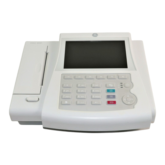
Equipment Overview General Description The MAC™ 800 is a 3- and 6-lead print, 12-channel display system with a 7 inch (17.78 cm) diagonal display, active patient cable, battery operation, and options for communication capabilities. Front View Name Description Screen Displays waveform and text data. AC LED Indicates when the unit is connected to AC power. -
Page 15: Side View
Equipment Overview Side View Name Description ECG signal input connector Connects the patient cable to the device. Secure digital (SD) card Houses the secure digital (SD) card for external slot storage. Back View Name Description Modem port Standard RJ-11 jack for connecting the modem to a telephone line. -
Page 16: Keypad
Equipment Overview Name Description LAN port Standard RJ-45 jack for connecting the device to a LAN. LEDs on the port indicate status. Solid green indicates a good connection. Flashing amber indicates network traffic. USB port Universal Serial Bus port used to connect external devices, such as the optional barcode reader. - Page 17 Equipment Overview Name Description ECG key Acquires a resting ECG and prints a 10-second report in Arrhythmia mode. Trimpad The arrows move the cursor left, right, up, or down. The center button moves the focus within a window or selects the currently active item. Rhythm key Prints a continuous, real-time rhythm ECG strip.
-
Page 18: Detailed Description
Equipment Overview Detailed Description Block Diagram MAC™ 800 2031504-159D... -
Page 19: Overview
Equipment Overview System Architecture Overview 2031504-159D MAC™ 800... -
Page 20: Hardware/Firmware Architecture
Power supply Housing Product Interfaces The MAC 800 system offers the following interfaces for connecting to external devices for data communication, software updates, and the control of workload devices: RS232 port (1) Connects to external systems, like MUSE or Cardiosoft. -
Page 21: Layered Structure Of Application Software
Equipment Overview Software Architecture Layered Structure of application software 2031504-159D MAC™ 800... -
Page 22: Ecg Data Flow With Sampling Rates
Equipment Overview ECG Data Flow With Sampling Rates 2-10 MAC™ 800 2031504-159D... -
Page 23: Troubleshooting
Troubleshooting 2031504-159D MAC™ 800... -
Page 24: General Fault Isolation
Troubleshooting General Fault Isolation Power-Up Self-Test See the MAC™ 800 Operator’s Manual, Chapter 2, “Equipment Overview: Getting Started” to verify operation. On power-up, the system automatically runs an internal self-test. If all circuit tests pass, you will see the start-up screen. The next screen that appears after the start-up screen depends on the Power Up mode selected in System Configuration. -
Page 25: Visual Inspection
Troubleshooting Visual Inspection A thorough visual inspection of the equipment can save time. Small things—disconnected cables, foreign debris on circuit boards, missing hardware, loose components—can frequently cause symptoms and equipment failures that may appear to be unrelated and difficult to track. -
Page 26: Event Logging
Event Logging Setting Up Event Logging The MAC 800 system can be set up to create an XML-format Event Log that contains system errors, warnings, and informational messages. Use the following procedure to configure the level of severity of messages written to the Event Log. -
Page 27: Exporting The Event Log
Windows operating system and open the log file with a text editor like Notepad or WordPad. If the Event Log is requested by GE Service for troubleshooting an issue, the file can be sent as an email attachment. -
Page 28: Accessing The System Diagnostics Function
Use the following procedure to access the System Diagnostics menu. 1. Power on the MAC 800 system by pressing the Power button. 2. From the Main Menu, press F4 to select System Configuration. 3. Press F6 (More) > F6 (More) > F5 (Service Setup). -
Page 29: Display Test
Troubleshooting The following sections describe how to perform the specific diagnostic tests. Proceed to the appropriate section for the test you need to perform. Display Test The Display Test can be used to determine if the display pixels are working properly. 1. - Page 30 Troubleshooting 4. Press the right arrow key on the Trimpad repeatedly to move the color bars horizontally across the screen. 5. Verify that the color band pattern (red, green, blue, white) scrolls across the screen. Pass the test if the pattern is replicated without discoloration. 6.
-
Page 31: Speaker Test
Troubleshooting 11. Select Pass or Fail: If the test passed, press F4 to select Yes. If the test failed, press F5 to select No. Replace the display assembly as described in “Replacing the LCD Assembly” on page 4-12. Speaker Test The Speaker Test can be used to determine if the speaker is working properly. -
Page 32: Acquisition Module Test
Troubleshooting 3. Press each key on the keyboard and verify the value appears in the corresponding representation of that key on the screen. A key passes the test if its value appears on the screen when the corresponding key is pressed. 4. -
Page 33: Battery Test
The Writer Test can be used to determine if the writer is working properly. NOTE Before performing the Writer Test, be sure that the correct thermal paper is properly loaded in the writer tray. Refer to the MAC 800 Resting ECG Analysis System Operator’s Manual for instructions on loading paper. 2031504-159D MAC™... - Page 34 Troubleshooting 1. Open the Diagnostic Tests window as described in “Accessing the System Diagnostics Function” on page 3-6. 2. Select the Writer Test button. The following window opens. 3. Perform the 50mm/s Speed Test. a. Select the 50mm/s Speed Test button. The writer prints the 50 mm/s speed test report.
-
Page 35: Rs232 Test
Troubleshooting 5. Perform the Print Head Test. a. Select the Print Head Test button. The writer prints a 1-page print head test report. b. Verify that there are no gaps in any of the lines printed. Up to 5 mm of blank paper is allowable at the top and bottom of the page. -
Page 36: Lan Test
LAN Test The LAN Test can be used to test network connectivity. 1. Connect the MAC 800 device to an active LAN. Ensure that the LAN is an active network. If you connect to an inactive network tap, the test result may be a false negative. -
Page 37: Modem Test
1. Open the Diagnostic Tests window as described in “Accessing the System Diagnostics Function” on page 3-6. 2. Connect a USB keyboard to the USB port of the MAC 800 back panel. 3. Select the USB Test button. The following window opens. 2031504-159D MAC™... -
Page 38: Patient Lead Wire Test
“Accessing the System Diagnostics Function” on page 3-6. 2. Connect a patient cable with lead wires to the MAC 800 patient cable connector. 3. Connect all leads to a patient simulator or shorting bar. 4. Select the Patient Lead Wire Check button. -
Page 39: Equipment Problems
Troubleshooting 5. Press the Enter key to select the Start Test button. For each lead wire, the test results are displayed. If the Connected message is displayed, the lead wire passes the test. If the Disconnected message is displayed, the lead wire fails the ... -
Page 40: Error Codes
Troubleshooting Error Codes No action is necessary for isolated error occurrences. However if the unit is malfunctioning and any of the following error messages are repeating and unrecoverable, replace the FRUs in the order as listed. Acquisition Error Codes If you repeatedly receive any of the following acquisition error codes, replace the mainboard assembly as described in “Replacing the Mainboard Assembly”... -
Page 41: Frequently Asked Questions
Troubleshooting Frequently Asked Questions Maintenance NOTE See the MAC™ 800 Operator’s Manual for complete System Configuration information. Save System Setups to SD Card Q: How do I save changes I have made to the System Configuration? A: Perform the following steps: 1. -
Page 42: Storing Ecgs
press Store? Cleaning Q: Should I clean the MAC 800? A: Clean the exterior surfaces of all the equipment and peripheral devices monthly, or more frequently if needed. Use a clean, soft cloth and a mild dish-washer detergent diluted in ... -
Page 43: Battery Capacity
Battery Capacity Q: What is the capacity of the battery? A: We recommend that the MAC 800 be connected to AC power through a wall outlet whenever it is not in use. However, if operating the device without AC power, be aware that a fully-charged battery is capable of printing approximately 1000 single page reports or 2 hours of continuous operation (without printing). -
Page 44: Location Number
Troubleshooting System Setup Location Number Q: When entering patient data, how do I get the Location field to automatically populate with the same number? A: The Location number can be set in Basic Setup to save you from entering it for each test. 1. -
Page 45: Passwords
They will generate a temporary, device-specific name and password that can only be used for 24 hours. 2. Log into the system with the password provided by GE Tech Support. 3. Immediately after logging into the system, verify your MAC 800 user name and password. -
Page 46: Editing
6. If you want the MAC 800 or 12SL Interpretation included on the ECG, check the Print Interpretation check box. 7. If you do not want the MAC 800 interpretation to print on the ECG, clear the Print Interpretation check box. -
Page 47: Resting Ecg Power Up Mode
3-26. Resting ECG Power Up Mode These steps describe how to navigate to the Main Menu after powering on the MAC 800 system when Resting ECG is selected for Power Up mode in Basic Setup. NOTE To perform system setup functions, log in as a user who is assigned setup editing privileges. -
Page 48: Arrhythmia Mode Power Up Mode
5. Press F5 to select Main Menu. Main Screen Power Up Mode These steps describe how to navigate to the Main Menu after powering on the MAC 800 system when Main Screen is selected for Power up mode in Basic Setup. NOTE To perform system setup functions, log in as a user who is assigned setup editing privileges. - Page 49 Troubleshooting The Main Menu is displayed. 2. If the system is configured for Main Screen Power up mode and does not have the High Security Mode enabled, the Main Menu appears after powering up the system. No further keys need be pressed in order to display the Main Menu.
- Page 50 Troubleshooting 3-28 MAC™ 800 2031504-159D...
-
Page 51: Maintenance
Maintenance 2031504-159D MAC™ 800... -
Page 52: Introduction
Current leakage tester Anti-static wrist strap MAC™ 800 Service Manual MAC™ 800 Operator’s Manual NOTE Always use an anti-static wrist strap while opening the MAC 800 unit to avoid possible damage due to static electricity. MAC™ 800 2031504-159D... -
Page 53: High-Level Fru Identification
Maintenance High-Level FRU Identification Top Cover Assembly Bottom Assembly Battery LCD Assembly 2031504-159D MAC™ 800... - Page 54 Maintenance Mainboard (A) and Internal Modem (B, option) Power Supply Assembly Writer Assembly Keypad Assembly Barcode Reader (option) MAC™ 800 2031504-159D...
-
Page 55: Fru Replacement Procedures
Maintenance Patient Cable Serial Cable Real-time Clock Battery FRU Replacement Procedures Preparing System for FRU Replacement Prior to performing any disassembly procedures, perform these steps. NOTE Take strict precautions against electrostatic discharge damage while replacing field replaceable units. 1. Power off the system. 2. -
Page 56: Replacing Barcode Reader
Maintenance 2. Disconnect the patient cable from the MAC 800 side panel connector as shown in the following illustration. 3. Connect the new patient cable to the side panel connector. 4. Perform the applicable checkout procedures. Refer to “Functional Checkout”... -
Page 57: Replacing The Battery Assembly
Maintenance b. While pushing the tool into the hole, pull the cable to remove it from the base of the barcode reader. 4. With a new cable, reverse the disassembly procedures to reassemble. Insert USB connector with (the USB symbol) facing down. 5. -
Page 58: Replacing The Real-Time Clock (Rtc) Battery
5 years (worst case calculation). In the normal case, the functioning period is assumed to be more than 10 years. NOTE Always use an anti-static wrist strap while opening the MAC 800 unit to avoid possible damage due to static electricity. 1. Remove the Mainboard Assembly as instructed in “Removing the... -
Page 59: Replacing The Top Cover Assembly
Maintenance 13. Perform the functional checkout and visual inspection procedures. See“Functional Checkout” on page 4-24. To check the RTC battery function, see “Real-time Clock” page 4-31. Replacing the Top Cover Assembly 1. Disconnect the system from AC power. 2. Remove the battery assembly as described in “Replacing the Battery Assembly”... - Page 60 Maintenance 7. Lift the top assembly approximately 1 inch at the back panel side. 8. Pull up the lock-release tab on mainboard keypad connector. 9. Disconnect the keypad cable as shown. 4-10 MAC™ 800 2031504-159D...
-
Page 61: Replacing The Keypad Assembly
Maintenance 10. Remove the eight screws from the bottom of the top cover assembly. 11. Separate the keypad from the top cover assembly. 12. Reassemble a new top cover assembly by reversing the steps for removal. 13. Perform the applicable checkout procedures. Refer to “Functional Checkout”... -
Page 62: Replacing The Lcd Assembly
Maintenance Replacing the LCD Assembly 1. Disconnect the system from AC power. 2. Remove the battery assembly as described in “Replacing the Battery Assembly” on page 4-7. 3. Remove the top cover assembly as described in “Replacing the Top Cover Assembly” on page 4-9. -
Page 63: Removing The Printer Assembly
Maintenance 6. Disconnect the inverter cable from the mainboard. 7. Disconnect the LCD cable from the mainboard. 8. Lift the LCD ASSY out of the BOTTOM ASSY. 9. Reassemble a new LCD ASSY by reversing the steps for removal. 10. Perform the applicable checkout procedures. Refer to “Functional Checkout”... - Page 64 Maintenance Remove the printer door from the bottom cover assembly as shown. 6. Disconnect the printer cable from the mainboard. 7. Remove the two screws from the printer mounting base as shown. 4-14 MAC™ 800 2031504-159D...
-
Page 65: Reassembling The Printer Assembly
Maintenance 8. Remove the printer motor from the printer mounting base. Reassembling the Printer Assembly 1. Replace a new printer motor on the bottom assembly as shown. 2. Replace the two mounting screws. 3. Reconnect the printer cable to the mainboard. 4. -
Page 66: Processing Ecgs In Internal Storage
Maintenance Replacing the Mainboard Assembly Processing ECGs in Internal Storage If the system has the internal storage option, process any ECGs remaining in storage by transmitting to your archival system and/or print them to ensure you have a printed record before proceeding with the mainboard replacement. - Page 67 Maintenance 6. Remove the 10 screws that hold the mainboard in place. 7. Lift the mainboard assembly approximately 1.5 inch. 8. Disconnect the battery cable from the bottom side of mainboard. 2031504-159D MAC™ 800 4-17...
-
Page 68: Reassembling The Mainboard Assembly
Maintenance 9. Disconnect the AD-DC cable from the bottom side of mainboard. Reassembling the Mainboard Assembly 1. Reconnect the AC/DC cable to the bottom of the new mainboard. 2. Reconnect the battery cable to the bottom of the new mainboard. 3. -
Page 69: Replacing The Internal Modem (Option)
Maintenance 11. Perform the applicable checkout procedures. Refer to “Functional Checkout” on page 4-24. Replacing the Internal Modem (option) 1. Disconnect the system from AC power. 2. Remove the battery assembly as described in “Replacing the Battery Assembly” on page 4-7. 3. - Page 70 Maintenance 7. Remove the two M3X12 flat screws from the shield plate as shown in the following illustration. 8. Remove the four hexagon screws from the shield plate as shown in the following illustration. 4-20 MAC™ 800 2031504-159D...
- Page 71 Maintenance 9. Remove the shield plate from the bottom cover assembly. 10. Remove the four hexagon screws of AC/DC as shown in the following illustration. 11. Lift the AC/DC and disconnect the AC inlet cable as shown in the following illustration. 2031504-159D MAC™...
-
Page 72: Reassembling The Power Supply Assembly
Maintenance Reassembling the Power Supply Assembly 1. Connect the AC inlet cable to the new AC/DC. 2. Place the new AC/DC in the bottom cover assembly. 3. Replace the four hexagon screws. 4. Route the AC/DC cable for mainboard as shown. 5. -
Page 73: Replacing The Fuse
Maintenance 5. Remove the printer assembly as described in “Removing the Printer Assembly” on page 4-13. 6. Remove the mainboard assembly as described in “Removing the Mainboard Assembly” on page 4-16. 7. Remove the power supply assembly as described in “Replacing the Power Supply Assembly”... -
Page 74: Functional Checkout
Maintenance 4. Reassemble the fuse holder into AC inlet. Functional Checkout The checkout procedures apply to all MAC 800 systems. NOTE The FRU checkout procedure for any listed FRU also applies to its internal PCBs and components. Perform the applicable product or product configuration dependant procedures when an asterisk (*) is listed. -
Page 75: Visual Inspection
3-17 for more information. Discuss electrode placement, skin prep, and patient-related requirements with the ECG technician. See Chapter 3, Preparing the Patient in the MAC 800 Operator’s Manual for more information. Verify the Keypad/LCD display filter passed inspection. -
Page 76: Operational Checks
Maintenance Verify the AC power cord passed inspection. “Visual Inspection” on page 3-3 for more information. Verify the battery pack passed inspection. “Visual Inspection” on page 3-3 for more information. Verify that all harnesses and internal wiring have been secured. “Visual Inspection”... -
Page 77: Electrical Safety Checks
Maintenance Verify the battery test was successful. “Battery Test” on page 3-11 for more information. Verify the LAN test was successful. “LAN Test” on page 3-14 for more information. Verify the modem test was successful. “Modem Test” on page 3-15 for more information. Electrical Safety Checks Verify the current leakage test results meet the requirements. -
Page 78: Updating Software
Maintenance Electrical Safety Checks Step Result Leakage Current Limits Condition UUT - ON Neutral Open, Reverse Polarity Pass/Fail ______ Reverse Polarity Pass/Fail ______ Ground Continuity Resistance Ac mains power cord ground prong to Pass/Fail ______ Less than 200m exposed metal surface (ground lug) - Page 79 Maintenance 3. Move the focus to 1=System Update in the boot loader Main Menu and select by pressing OK to start the software update. 4. Boot loader will read the software from the SD card and write into Flash. Do not press any key until the Writing image completed message displays.
-
Page 80: Conditioning The Battery Pack
A condition cycle consists of an uninterrupted “charge-discharge-charge” cycle. You can condition the MAC 800 battery pack while installed in the MAC 800 system that is not being used to record tests on a patient. 1. Disconnect the AC mains power from the MAC 800 system. -
Page 81: Real-Time Clock
The amber Battery LED indicator will light while the unit is charging and turn off when charging is complete. 6. Remove the AC mains power and turn on the MAC 800 unit. 7. Leave the unit on and allow the battery to discharge until the MAC 800 system shuts off. - Page 82 Maintenance 4-32 MAC™ 800 2031504-159D...
-
Page 83: Parts Lists
Parts Lists 2031504-159D MAC™ 800... -
Page 84: Ordering Parts
FRUs, and FRU kits considered field serviceable. Only items, assemblies, and kits which have part numbers given in this chapter are available for purchase as FRUs. To order parts, contact GE Healthcare Service Parts. MAC™ 800 2031504-159D... -
Page 85: Field Replaceable Units (Frus)
MAC 800 Upper Level Assembly Diagrams The following diagrams identify the field replaceable units of the MAC 800 system. The numbers in the callouts reference part descriptions found in “MAC 800 Upper Level Assembly Part List” on page 5-9. 2031504-159D MAC™ 800... - Page 86 Parts Lists MAC™ 800 2031504-159D...
- Page 87 Parts Lists 2031504-159D MAC™ 800...
- Page 88 Parts Lists MAC™ 800 2031504-159D...
- Page 89 Parts Lists 2031504-159D MAC™ 800...
- Page 90 Parts Lists MAC™ 800 2031504-159D...
-
Page 91: Mac 800 Upper Level Assembly Part List
Parts Lists MAC 800 Upper Level Assembly Part List The following table identifies the parts available for the MAC 800 system. The numbers in the Item column refer to the callouts from the diagrams found in “MAC 800 Upper Level Assembly Diagrams”... - Page 92 Parts Lists 800 Upper Level Assembly (Continued) Item Part Number Item Description PCB MAC800 MAINBOARD Included with “FRU Mainboard Assembly, PN 2039942-001” on page 5-14 REAR PANEL Included with “FRU Mainboard Assembly, PN 2039942-001” on page 5-14 ACQ COVER1 Included with “FRU Mainboard Assembly, PN 2039942-001”...
- Page 93 Parts Lists 800 Upper Level Assembly (Continued) Item Part Number Item Description HEXAGON SCREW2 Included with: “FRU Bottom Cover Assembly, PN 2039943-001” on page 5-15 “FRU Kits, PN 2039945-001” on page 5-20 SHIELD PLATE Included with “FRU Bottom Cover Assembly, PN 2039943-001” on page 5-15 CLIP-ON SHIELD COVER Included with...
- Page 94 Parts Lists 800 Upper Level Assembly (Continued) Item Part Number Item Description FOOTPAD3 Included with: “FRU Bottom Cover Assembly, PN 2039943-001” on page 5-15 “FRU Kits, PN 2039945-001” on page 5-20 HINGE LEFT Included with “FRU Bottom Cover Assembly, PN 2039943-001” on page 5-15 HINGE RIGHT Included with...
-
Page 95: Fru Top Cover Assembly, Pn 2039939-001
LCD POLY FOAM LCD LENS PRINTER BUTTON TOP COVER NAMEPLATE 15MM GE LOGO FRU Printer Assembly, PN 2039941-001 The following table summarizes the items in the FRU Printer Assembly. Item numbers correspond to the item numbers in the “MAC 800 Upper Level Assembly Diagrams”... -
Page 96: Fru Mainboard Assembly, Pn 2039942-001
Parts Lists FRU Mainboard Assembly, PN 2039942-001 The following table summarizes the items in the FRU Mainboard Assembly. Item numbers correspond to the item numbers in the “MAC 800 Upper Level Assembly Diagrams” on page 5-3. FRU Mainboard Assembly, PN 2039942-001 Item Description M3X8 MACHINE SCREW PHILIPS PAN NI... -
Page 97: Fru Bottom Cover Assembly, Pn 2039943-001
Parts Lists FRU Bottom Cover Assembly, PN 2039943-001 The following table summarizes the items in the FRU Bottom Cover Assembly. Item numbers correspond to the item numbers in the “MAC 800 Upper Level Assembly Diagrams” on page 5-3. FRU Bottom Cover Assembly, PN 2039943-001 Item Description M3X8 MACHINE SCREW PHILIPS PAN NI... -
Page 98: Model Data Matrix Barcode Scanner Kits
Item Description AC INLET MODULE AC INLET HOUSE MODULE PCB MAC800 BATTERY INTERFACE BD Model Data Matrix Barcode Scanner Kits MAC 800 Data Matrix Barcode Scanner Kits Part Number Description 2041391-001 MAC 800 FRU USB BARCODE SCANNER ENG 2041391-002 MAC 800 FRU USB BARCODE SCANNER GER... -
Page 99: Keypads
Parts Lists MAC 800 Data Matrix Barcode Scanner Kits (Continued) Part Number Description 2041391-016 MAC 800 FRU USB BARCODE SCANNER RUS 2041391-017 MAC 800 FRU USB BARCODE SCANNER SLO 2041391-018 MAC 800 FRU USB BARCODE SCANNER POR 2041391-020 MAC 800 FRU USB BARCODE SCANNER FIN... -
Page 100: Power Cords
Parts Lists MAC 800 Keypad Assemblies Part Number Description 2040049-001 MAC800 FRU KEYPAD ASSEMBLY ENGLISH 2040049-002 MAC800 FRU KEYPAD ASSEMBLY RUSSIAN NOTE The Russian Keypad (2040049-002) is used only in Russia; all other countries use the English Keypad (2040049-001). Power Cords... -
Page 101: Serial Cable
Parts Lists Serial Cable MAC 800 Serial Cable Part Number Description 2041488-001 MAC800 FRU SERIAL CABLE MAC800 FRU Battery Coin 3V, PN 2044674-001 MAC800 FRU Battery Coin 3V Part Number Description 2044674-001 MAC800 FRU Battery Coin 3v (including packaging and labeling) 2031504-159D MAC™... -
Page 102: Fru Kits, Pn 2039945-001
Parts Lists FRU Kits, PN 2039945-001 FRU Kits, PN 2039945-001 Item Description M3X8 MACHINE SCREW PHILIPS PAN NI M2X6 MACHINE SCREW PHILIPS PAN AN00388 4-40X3/8 SCREW NI FLAT SCREW M3X12 CRIMP RING .217 M4X16 MACHINE SCREW PHILIPS PAN NI HEXAGON SCREW1 HEXAGON SCREW2 CABLE FOR MAIN BOARD CABLE FOR BATTERY... -
Page 103: Technical Specifications
Technical Specifications 2031504-159D MAC™ 800... -
Page 104: Features And Functions
Support for USB barcode (GE-supported) (option) Transmit acquired ECG to MUSE system (option) Transmit acquired ECG to CardioSoft system (option) LAN (transmission to GE ECG management System) (option) Keyboard Telephone Keypad Application Options RR Analysis ... -
Page 105: Specifications
Technical Specifications Features and Functions Languages English German French Italian Spanish Portuguese (Brazilian Portuguese) Hungarian Polish Czech Slovak Simplified Chinese Russian Korean Japanese Finnish Swedish ... - Page 106 Technical Specifications Specifications Pressure Operating Pressure: 700 hPa to 1060 hPa Storage Pressure: 500 hPa to 1060 hPa Warranty 1 year Certifications IEC 60601-1: 1988 +Amd-1: 1991 +Amd-2: 1995 General Requirements for Safety IEC 60601-1-1: 2000 Medical Electrical Equipment: General ...
-
Page 107: Classification
Technical Specifications Classification Type of protection against Class I, internally powered equipment electrical shock Degree of protection Type CF defibrillation-proof applied part against electrical shock Degree of protection Ordinary Equipment (enclosed equipment without against harmful ingress of protection against ingress of water). water Degree of safety of Equipment not suitable for use in the presence of a... - Page 108 Technical Specifications MAC™ 800 2031504-159D...
-
Page 109: B Electromagnetic Compatibility
Electromagnetic Compatibility 2031504-159D MAC™ 800... -
Page 110: Electromagnetic Compatibility (Emc) Overview
Guidance and Manufacturer’s Declaration - Electromagnetic Emissions The MAC 800 is intended for use in the electromagnetic environment specified below. It is the responsibility of the customer or user to ensure that the MAC 800 system is used in such an environment. -
Page 111: Guidance And Manufacturer's Declaration - Electromagnetic Immunity
The MAC 800 system is intended for use in the electromagnetic environment specified in the following table. It is the responsibility of the customer or user to ensure that the MAC 800 system is used in such an environment. Electromagnetic Environment -... -
Page 112: Recommended Separation Distances
The MAC 800 system is intended for use in the electromagnetic environment on which radiated RF disturbances are controlled. The customer or the user of the MAC 800 system can help prevent electromagnetic interference by maintaining a minimum distance between portable and mobile RF communications equipment (transmitters) and the MAC 800 system as recommended below, MAC™... -
Page 113: Emc-Compliant Cables And Accessories
The following table lists cables, transducers, and other applicable accessories which GE Healthcare claims are EMC compliant. NOTE Any supplied accessories that do not affect EMC compliance are not included. - Page 114 PWR CRD ST CHINA RA PLUG 10A 250V 2.5M 405535-011 PWR SPLY CRD ST-RA PSE 10A 250V 10FTROHS 2040758-001 USB BARCODE SCANNER WITH MAGNET RING ENG 2037082-001 MAC 800 BATERY ASSEMBLY 2040494-001 MAC800 SERIAL CABLE FEMALE TO MALE 1.83M 2038704-001 MODEM SOCKET MT9234SMI V.92 MAC™ 800...
-
Page 115: C Supplies & Accessories
Supplies & Accessories 2031504-159D MAC™ 800... -
Page 116: Introduction
Supplies & Accessories Introduction This section of the manual lists the supplies and accessories that are supported by the MAC 800 system and are recommended for use by GE Healthcare. Standard Accessories Part Number Description 22341808 Patient trunk cable, 10-lead IEC... -
Page 117: Thermal Papers
Supplies & Accessories Thermal Papers Part Number Description 2036970-001 Z-FOLD PAPER-110MM WIDTH-MAC800 Serial Cable Part Number Description 2040494-001 MAC800 SERIAL CABLE FEMALE TO MALE 1.83M Country-Specific Power Cords Part Number Description 401855-101 PWR SPLY CRD ST CONT EURO 10A 250V 2.5M 401855-102 PWR SPLY CRD ST BRITSH 10A 250V 2.5M FSD 401855-103... -
Page 118: Optional Accessories
Supplies & Accessories Optional Accessories Part Number Description 21612413 SUCTION SYSTEM KISS 10-LEAD MSMART W/PMP 2005836-006 NEHB Leadwire MAC™ 800 2031504-159D... - Page 119 Index Index interfaces ..............2-8 LED..............2-2 power connector ..........2-4 keyboard acq module diagnostic test ........3-10 diagnostic test........... 3-9 acquisition error codes .......... 3-18 internal.............. 2-4 replacing ............4-12 backspace key ............2-5 USB connector for ..........2-8 barcode reader, replacing ........
- Page 120 Index rhythm key .............. 2-5 RJ-11 jack ............... 2-3 T9 key ..............2-5 RS232 diagnostic test ........... 3-13 telephone jack............2-3 trimpad ..............2-5 screen ..............2-2 SD card Universal Serial Bus, see USB how to insert ........... 3-19 slot ..............2-3 diagnostic test..........
- Page 122 Asia Headquarters GE Medical Systems GE Medical Systems GE Medical Systems Information Technologies GmbH Information Technologies, Inc. Information Technologies Asia; GE (China) Co., Ltd. 8200 West Tower Avenue Munzingerstrasse 5 No.1 Huatuo Road Milwaukee, WI 53223 USA D-79111 Freiburg, Germany...