Honeywell 7800 Series Product Data
Hide thumbs
Also See for 7800 Series:
- Product data (64 pages) ,
- Manual (56 pages) ,
- Installation instructions manual (40 pages)
Advertisement
Quick Links
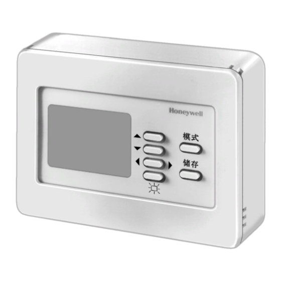
7800 SERIES S7800B Display Module
APPLICATION
The Honeywell 7800 SERIES is a microprocessor based
integrated burner control for automatically fired gas, oil, coal or
combination fuel single burner applications. The 7800 SERIES
consists of a Relay Module, Subbase and Amplifier. Options
include Keyboard Display Module, Purge Card, Personal
Computer Interface, Data ControlBus Module™, Remote
Display mounting, First-Out Expanded Annunciator (RM78XX
only) and Combustion System Manager® Software.
The 7800 SERIES is programmed to provide a level of safety,
functional capability and features beyond the capacity of
conventional controls.
Functions provided by the 7800 SERIES include automatic
burner sequencing, flame supervision, system status
indication, system or self-diagnostics and troubleshooting.
® U.S. Registered Trademark
Copyright © 1996 Honeywell Inc. • All Rights Reserved
FEATURES
• Two languages on the display:
-
Chinese
-
English
• Application flexibility.
• Dependable, long-term operation provided by
microcomputer technology.
• First-out annunciation and system diagnostics
provided by a 128 x 64 pixel backlit liquid crystal
display (LCD) located on the S7800B Display Module.
• Remote annunciation of operation and fault
information.
• Report generation.
• Burner controller data:
-
Sequence status.
-
Sequence time.
-
Hold status.
-
Lockout/alarm status.
-
Flame signal strength.
-
Total cycles of operation.
-
Total hours of operation.
-
Fault history of six most recent faults:
•
Cycles of operation at time of fault.
•
Fault message and code.
•
Hours of operation at time of fault.
•
Sequence status at time of fault.
•
Sequence time at time of fault.
-
Diagnostic information:
•
Device type.
•
Flame amplifier type.
•
Flame failure response time.
•
Manufacturing code.
•
On/Off status of all digital inputs and outputs.
•
Prepurge time selected.
•
Software revision and version of 7800 SERIES
Relay Module and S7800B Display Module.
•
Status of configuration jumpers.
•
Status of Run/Test Switch.
Application ........................................................................... 1
Features .............................................................................. 1
Specifications ...................................................................... 2
Ordering Information ........................................................... 2
Installation ........................................................................... 3
Wiring .................................................................................. 5
Troubleshooting ................................................................... 8
X-XX UL
PRODUCT DATA
Contents
65-0219-1
Advertisement

Related Manuals for Honeywell 7800 Series


Summary of Contents for Honeywell 7800 Series
-
Page 1: Table Of Contents
Combustion System Manager® Software. • Manufacturing code. • On/Off status of all digital inputs and outputs. The 7800 SERIES is programmed to provide a level of safety, • Prepurge time selected. functional capability and features beyond the capacity of •... -
Page 2: Specifications
SHOWN WITH TRIM RING REMOVED. Fig. 1. Approximate dimensions of S7800B in in. (mm). ORDERING INFORMATION When purchasing replacement and modernization products from your 7800 SERIES distributor, refer to the TRADELINE ® Catalog for complete ordering number. If you have additional questions, need further information, or would like to comment on our products or services, please write or phone: 1. -
Page 3: Installation
7800 SERIES S7800B DISPLAY MODULE INSTALLATION Preparation 1. Remove the S7800B from its package. Set aside any mounting materials (screws, plastic screw anchors, When Installing this Product… etc.) until later in the mounting procedure. 1. Read these instructions carefully. Failure to follow them 2. - Page 4 7800 SERIES S7800B DISPLAY MODULE PLASTIC SCREW ANCHOR (4) (NOT USED FOR METAL PANELS) HOLE IN WALL OR PANEL WIRING TO CONTROL MODULE SURFACE-MOUNTING BOX SCREW (4) SURFACE- MOUNTING BOX LEAD WIRES S7800B MOUNTING SCREW (4) M11104 Fig. 3. S7800B surface mounting.
-
Page 5: Wiring
If more than one Display Module is remote mounted, S7800A KEYBOARD DISPLAY MODULE OR S7810A DATA CONTROLBUS MODULE™ wire the module in a daisy chain configuration. (MOUNTED ON 7800 SERIES RELAY MODULE) NOTE: If termination resistors are being used, install MOMENTARY PUSHBUTTON... - Page 6 ), see Fig. 8. message after 60 seconds if it or a lockout message is available. The 7800 SERIES Relay Module LEDs provide positive visual indication of the Relay Module sequence. The LEDs are energized simultaneously with the correct sequence description.
- Page 7 7800 SERIES S7800B DISPLAY MODULE 4. BACKLIGHT pushbutton, see Fig. 9. The BACKLIGHT pushbutton turns on the backlight. (All other pushbuttons turn on the backlight when pressed once; when pressed a second time, the function is initiated.) If no pushbutton is pressed for a two-minute period of time, the backlight turns off.
-
Page 8: Troubleshooting
Table 2 to access historical and diagnostic information. Information available in the Diagnostic Information Self-diagnostics of the 7800 SERIES enables it to detect and includes Device Type, Device Suffix, Software Revision, annunciate both external and internal system problems. Internal... - Page 9 7800 SERIES S7800B DISPLAY MODULE SERVICE NOTE: Reset the 7800 SERIES Relay Module by Historical Information Index pressing the reset pushbutton on the 7800 The S7800B displays historical information for the six most SERIES Relay Module, or pressing a recent lockouts. Each of the six lockout records retain the...
- Page 10 Device suffix number. nnnn — Run/Test Sw. Position of Run/Test Switch. RUN or TEST Indicates if 7800 SERIES is in RUN or TEST mode. OperControl Operating Control Input. = 1 or 0 Indicates if input is on or off, energized or de-energized.
- Page 11 Preignition Interlock Terminal 17 or 20 is model dependent. Lockout Messages When the 7800 SERIES is locked out, it displays a repeating cycle of messages; see Table 4. There are four states in the cycle: 1. STATE 1, see Fig. 11: First state message display lasts six seconds.
- Page 12 7800 SERIES S7800B DISPLAY MODULE Table 4. Fault Message and Recommended Troubleshooting. Fault Code System Failure Recommended Troubleshooting Fault 01 No card is plugged into the 1. Assure the purge card is seated properly. No Purge Card purge card slot 2.
- Page 13 7800 SERIES S7800B DISPLAY MODULE Table 4. Fault Message and Recommended Troubleshooting (continued) . Fault Code System Failure Recommended Troubleshooting Fault 10 Preignition interlock fault 1. Check wiring, correct any errors. Preignition ILK during Standby. 2. Check Preignition Interlock switches to assure that they function properly.
- Page 14 7800 SERIES S7800B DISPLAY MODULE Table 4. Fault Message and Recommended Troubleshooting (continued) . Fault Code System Failure Recommended Troubleshooting Fault 15 Flame sensed when shutter 1. Check that flame is not present in the combustion chamber; correct Flame Detected open and no flame is any errors.
- Page 15 7800 SERIES S7800B DISPLAY MODULE Table 4. Fault Message and Recommended Troubleshooting (continued) . Fault Code System Failure Recommended Troubleshooting Fault 21 Running interlock fault 1. Check wiring; correct any errors. Running ILK during Prepurge. 2. Inspect the fan, assure that there is no blockage of the air intake and that it is supplying air.
- Page 16 7800 SERIES S7800B DISPLAY MODULE Table 4. Fault Message and Recommended Troubleshooting (continued) . Fault Code System Failure Recommended Troubleshooting Fault 28 Pilot flame failure. 1. Check pilot valve wiring and operation. Correct any errors. Pilot Flame Fail 2. Check fuel supply.
- Page 17 7800 SERIES S7800B DISPLAY MODULE Table 4. Fault Message and Recommended Troubleshooting (continued) . Fault Code System Failure Recommended Troubleshooting Fault 34 CTL input was energized at 1. Check wiring, correct any errors. Control On the wrong time for the 2.
- Page 18 7800 SERIES S7800B DISPLAY MODULE Table 4. Fault Message and Recommended Troubleshooting (continued) . Fault Code System Failure Recommended Troubleshooting Fault 46 This fault indicates either 1. Remove power to the device. Reseat the flame amplifier. Reset and Flame Amp Type that the Flame Failure sequence.
- Page 19 7800 SERIES S7800B DISPLAY MODULE Table 4. Fault Message and Recommended Troubleshooting (continued) . Fault Code System Failure Recommended Troubleshooting Fault 54 Combustion pressure 1. Check wiring; correct any errors. Comb. Pressure switch fault (Fulton pulse). 2. Inspect the Combustion Pressure Switch to assure that it is functioning properly.
- Page 20 7800 SERIES S7800B DISPLAY MODULE Table 4. Fault Message and Recommended Troubleshooting (continued) . Fault Code System Failure Recommended Troubleshooting Fault 110 The configuration jumpers 1. Inspect the jumper connections. Assure that they match the original Internal Fault differ from stored values.