Table of Contents
Advertisement
Quick Links
Advertisement
Table of Contents

Related Manuals for AEG AMP 4

Summary of Contents for AEG AMP 4
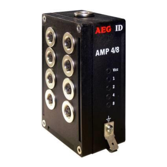
- Page 1 Antenna multiplexer AMP 4/8 Installation guide...
-
Page 2: Table Of Contents
INTRODUCTION ......................4 INSTALLATION ......................4 Mounting of the housing ..........................4 Grounding of the AMP 4/8 ........................4 Connecting of the plug ..........................5 Connecting of the power supply cable ......................6 2.4.1 Using the connecting cable for AMP und ARE i2 (RS232) ..............6 2.4.2... - Page 3 STARTUP AND TESTING THE AMP 4/8 ..............17 HOTLINE ........................18 REVISIONS ......................... 18 ANHANG ........................19 --------------------------------------------------------------------------------3/20--------------------------------------------------------------------------------...
-
Page 4: Introduction
the protection class of the housing is IP65 Installation To ensure a proper function of the AMP 4/8 you have to follow the steps in following chapters. The installation should be done by trained people. Mounting of the housing The AMP 4/8 can be mounted to any other mechanic construction. -
Page 5: Connecting Of The Plug
Attention! The topology of the ground wires must be done in the right way (according state of art). Connecting of the plug Attention! Be sure that the grounding of the reader is well done and the power supply is not connect- ed(chapter 3.2). -
Page 6: Connecting Of The Power Supply Cable
Power supply: brown = + 9 .. 30 Volt white = ground Interface: green = RXD (Dataout AMP 4/8) yellow = TXD (Dataout AMP 4/8) grey = ground 2.4.3 Using the switchboard cable for AMP (binär) Power supply: brown = + 9 .. -
Page 7: Using A Self Assembled Connecting Cable
2.4.4 Using a self assembled connecting cable Using the following SAB cabs you can assemble your own connecting cable. ID 70211 SAB cab with 1 PG9 cable pipe ID 70215 SAB cab with 2 pre-assembled cable pipes ID 70219 SAB cab without any cable pipe You can use any shielded five-pole cable. - Page 8 Remove all inner parts from the cable pipe at the SAB Cab (1) ( nut (5), cable fastener (3), pipe(4)) (see Figure 4) Put all the removed parts (nut (5), cable fastener (3), pipe (4),) and the cable pipe of the SAB Cab as well (1 to 4) to the cable.
-
Page 9: Pin Assignment Of The Sab Connector
AMP/ARE i2 RXD/D- Shield/VBus Schirm(RS232) / VBus(USB) TXD/D+ B2 (binary control) GND (0V) B1 (binary control) V+ (+24V) B0 (binary control, LSB) AMP 4/8 blue gray Data Data line B3 (binary control, MSB) AMP/ARE i2 RXD/D- Shield/VBus Schirm(RS232) / VBus(USB) -
Page 10: Visual Signal Lamps
Visual signal lamps You can see the state of the AMP 4/8 on the lamps. Vcc: twinkles, if the processor works 1, 2, 4, 8: show the active channel of the AMP 4/8 (binary) AMP4/8 examples: LED 1: channel 1... -
Page 11: Entering Instructions
4.1.1 Entering instructions The protocol format is as follows Command <SP> parameter <CR> The space character <SP> separates commands from parameters and the <CR> character acts as command line terminator. For commands without parameter values (e.g. GT ) the <SP> character and parameter values are omitted. -
Page 12: Change Of The Mode
1..4 of the AMP4. The parameter 0 switches all channels off. Mode 3: The controlling is binary via the states of the digital inputs. Version This instruction is used to get the firmware version of the AMP 4/8. instruction: VER <CR> answer: AEG ID AMP 4 V1.423<CR>... -
Page 13: Saving Of The Parameters
<CR> Changing the baudrate With this instruction you can change the baudrate of the AMP 4/8. The default setting is 2 (19200 baud). This instruction has to be saved with the instruction VSAVE. The AMP 4/8 is effected after a warmstart (RST) or coldstart. -
Page 14: System Overview
System overview The complete reading system contains the AMP 4/8 and the reader ARE i2. There a 3 different modes to use the AMP 4/8: Mode 1: RS232/USB communication Mode 2: communication via the ARE i2 Mode 3: binary controlling via the digital in puts... -
Page 15: Controlling Via Reader Are I2 (Mode 2)
ARE i2 und AMP 4/8) Figure 4: system overview controlling via reader ARE i2 (mode 2) In mode 2 the power supply and the data line of the AMP 4/8 is connected directly to the SAB cap of the ARE i2. -
Page 16: Controlling Via Digital Inputs (Mode 3)
Figure 5: system overview controlling via digital inputs (mode 3) In mode 3 the power supply of the AMP 4/8 and the ARE i2 are seperatly. The switching of the channels is done binary via the digital inputs. The inputs are low-activ, that means that you have to pull them to ground to get a logical ‘1’... -
Page 17: Startup And Testing The Amp 4/8
After switching to a new antenna channel the ARE i2 can read the transponder in the antenna field. Attention! Be sure that the ARE i2 is not reading (GT or MD0) while the AMP 4/8 switches the channel. The reader can hang up or can be damaged. -
Page 18: Hotline
XOFF/XON). Send the command „VER <CR>“ to the AMP. The reader answers with the actual firmware version (e.g. AEG ID AMP8 V1.3). Change to mode 1 with the command “MO 1” (the default value is MO 2) ... -
Page 19: Anhang
Anhang A: Abmessungen AMP 4/8 AMP 4/8 SAB-Haube Deckel mit Dichtung Datum Name Bauteilname AMP 4/8 Bearb Abbildung 3: Maßbild Farbe schwarz Gepr. Gehäuseboden und Deckel Norm. Gehäuse IP65 PA6 30% GF BASF Ultramid A3X2G5 UL 94 V-1 Dokumenten-Nr.: 999.039.MB Blatt Neuerstellung 09.06.09... - Page 20 B: Orientierung von Transpondern Externe Antennen AAN Xxx für kompakt Lesegerät ARE i2 und AMP 4/8 external antenna for compact Reader ARE i2 and AMP 4/8 Lesefeld / Reading Coil Beste Orientierung / Best Orientation Luftspule / air coil AAN XxL...