
Related Manuals for Honeywell MPA1C1


Summary of Contents for Honeywell MPA1C1
- Page 1 MPA1C1 Access Control Unit Installation Guide For MPA1C1 Controller and MPA1ENCP Plastic Enclosure Document 800-26169 09/2020 Rev E...
- Page 2 All product and brand names are the service marks, trademarks, regis- tered trademarks, or registered service marks of their respective owners. Printed in the United States of America. Honeywell reserves the right to change any information in this document at any time without prior notice.
- Page 3 Installing the MPA1C1 Panels • Introduction beginning on page 3 • Panel Components and Descriptions beginning on page 5 • Download and Install App beginning on page 13 • Mounting and Installing Options beginning on page 14 • MPA1ENCP Plastic Enclosure Installation beginning on page •...
- Page 4 Introduction This document describes how to install the MPA1C1 access control unit.
- Page 5 Access Control Overview An access control system protects and preserves an enterprise’s resources by providing authentication, authorization, and administration services. Authentication is a process that verifies a user’s identity. If the user is verified, the system then either grants or denies access to specific areas and resources.
- Page 6 An MPA1C1 access control unit is a full-featured single-door web-based smart edge access control system. The MPA1C1 panel includes a built-in web server, built-in Ether- net, and PoE (Power over Ethernet) capability. You can manage the access control system using either a web browser, MPC (MAXPRO®...
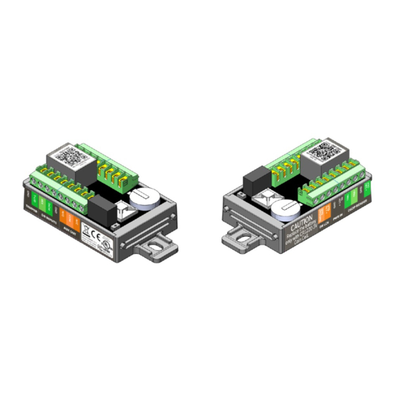
- Page 7 MPA1C1 Compact Enclosure wiring connections Note: • Install according to ANSI/NFPA70 National Electrical Code and local codes. • All wiring except for the CAT5 Cable shall be shielded wire. • Terminal blocks are rated for 12-26 AWG wiring. • UL Listed and suitably rated ferrule connectors have to be used in case of braid copper wires or in case of two wires connected to one screw terminal.
- Page 8 MPA1C1 door with single-reader and door strike MPA1C1 door with two-readers and door strike...
- Page 9 MPA1C1 Access Control Unit You can use the MPA1C1 panel as a standalone panel with inde- pendent card and transaction storage or, with a host software upgrade, as a fully monitored online access control device. The three panel inputs are capable of four state supervision: Normal, Alarm, Short and Cut.
- Page 10 100 days in the absence of pri- mary power. Ensure the battery coin cell has been placed in the battery holder when MPA1C1 is commissioned and when in normal operation. Replace the battery only with CR1220 Coin Cell type. Using another type of battery may result in a risk of Fire Or Explosion.
- Page 11 The MPA1C1 can be powered from PoE or an external 12VDC power supply. Power over Ethernet The MPA1C1 controller can be powered by Power over Ethernet (PoE - 802.3af). This PoE can supply a total system current of 1070mA @12VDC.
- Page 12 (such as Magnetic locks), where output current for the lock would exceed 500mA. Backup power The MPA1C1 can be powered from PoE or an external power supply. The backup power supply must be connected to the power source. Recommended backup power source...
- Page 13 Reset button MPA1C1 has a reset button. While MPA1C1 is powered up and RUN LED is blinking, press the reset button for 20 seconds to reset to factory default configurations and activate the Blue- tooth communication for the commissioning application.
- Page 14 Download and Install App The panel needs the Device Utility App (Bluetooth Mobile App) to complete commissioning. Download the application from the App Store or Play Store. Scan this QR code for the application in the App Store. Get Device Utility App Here Scan this QR code for the application in the Play Store.
- Page 15 Mounting and Installing Options The MPA1C1 controller (MPA1C1) has been designed to fit in a single gang US electrical gang box. For compliance with UL294 and CAN/ULC60839- 11-1, the MPA1C1 is intended to be installed within the secure/protected area. To mount the MPA1C1: •...
- Page 16 The MPA1C1 Controller slides and snaps into the enclosure inner base without using any tools. Make sure that the RJ45 Connector is on the outer left side. The below figures show how to insert the MPA1C1 controller in the MPA1ENCP inner base.
- Page 17 Note: The MPA1C1 Controller has been installed already in the MPA1ENCP enclosure.
- Page 18 Wiring the enclosure tamper switch The Lid tamper switch wires connect with the T-Lid inputs as demonstrated below. Note: There is an additional internal accelerometer tamper switch that will detect any movement from the wall or from a gang box...
- Page 19 Fix Wirings The design of the base is so that the wiring can be lead neatly in the cabinet using the openings at the edges of the inner base. The cables can be tied down the using the cable ties at the cable tie points.
- Page 20 Break out tabs in the cover Cables can be lead in the side of the cover when breaking out the break out tabs per picture below.
- Page 21 Fix enclosure base to the wall Fix the plastic enclosure base to the wall using 4 large screws (not included in the accessory bag). Make sure the secure fixing is suitable for the material of the wall. Note the location of the fixing holes.
- Page 22 The Inner Base The inner part (inner base) of the base can be snapped out of the outer part.Turn the base, facing the full base from the back side. Push the indicated plastic clips out. Move the inner base towards you.
- Page 23 Take out the inner base and turn it facing the labels toward you. and snap in the MPA1C1 panel.
- Page 24 The inner base (with MPA1C1) can now be mounted on other devices or in a metal cabinet, using 2 or 4 short cabinet mount- ing screw supplied in the accessory bag.
- Page 25 The inner base can be mounted on top of a MPA2 controller, a MAXPRO intrusion smart power supply or on the bottom of the metal enclosure. The inner base can also be mounted on a DIN- Rail using DIN-Rail adapters. Note: Above mounting option is not evaluated by UL294 and CAN/ULC60839-11-1.
- Page 26 OSDP (Open Supervised Device Protocol) is a bi-directional RS485 multi-drop AES128 Encrypted protocol. The MPA1C1 provides a single OSDP connection for the door which can have 2 OSDP readers connected (Address ‘01’ = Entry reader and Address ‘02’ = Exit reader).
- Page 27 ‘01’ when the panel is powered up, for example, when commissioning the panel for the first time. To connect OUT reader, power-off MPA1C1 and connect the OUT reader in addition to the IN reader. The OUT reader will be automatically readdressed ‘02’...
- Page 28 Wiring Electrical Door Lock Wire door strikes and magnetic locks. Wiring Door Strikes • Follow these steps to wire door strike to the Controller Board: • Use the following figure to locate the door strike terminals on the controller and to wire the door strike lock according to the power supply used.
- Page 29 Wiring a Magnetic Lock Use the following instructions to wire a heavy duty magnetic lock to the Controller Board: • Use the following figure to locate the AUX OUTPUT voltage free terminals on the controller and to wire the magnetic lock according to the powersupply used.
- Page 30 Wiring auxiliary output The auxiliary relay output can be used to connect voltage / potential free connections upto 2A @ 30VDC. Power Factor is 0.6. There are 3 outputs at the AUX OUT terminal block: • N/C (Normally Closed): Connected to COM when relay is not energized •...
- Page 31 Supervised and non-supervised input wiring The supervised inputs are located on the following terminal blocks: Non-supervised input Terminal Blocks Default Board Configuration Terminal Block DrCnt (Door Contact) N/C DR INPUTS (GND, DrCnt) REX (Request To Exit) N/C DR INPUTS (GND, REX) T-LID (Cover Tamper) N/C TAMPER (GND, T-LID) Door Status (DrCnt) and Request to Exit (REX) may be config-...
- Page 32 Supervised and non-supervised input wiring For Supervised inputs standard 2.2K ohm resistors will be used. The MPA1C1 panel accepts only 2.2K ohm values. The wire used for the inputs cannot exceed 30 ohms over the entire length of the cable.
- Page 33 Connect Ethernet cable Ethernet cable can be with Power over Ethernet. The Enclosure has been designed to lead the Ethernet cable as smooth as pos- sible and to lead away from the tamper switch.
- Page 34 • Access control device in WIN-PAK • Stand-alone web enabled Panel (Primary or Secondary). Note: The App will ask to reset the MPA1C1 in order to activate the Bluetooth. Press the reset button for 20 seconds to reset to factory default configurations and activate the Bluetooth communication for the commissioning application.
-
Page 35: System Configuration
System Configuration This section provides wiring diagrams for each of the system configurations. Ethernet Connection for standalone web mode MPA1C Panel MPA1C Panel Note: UL294 and CAN/ULC60839-11-1 evaluation consists of the stand alone mode of this device. - Page 36 Ethernet Virtual Loop (EVL) with all panels on common IP Subnet MPA1C1 MPA1C 1(Pri- Primary mary) Note: • The Network must provide DHCP server (or use dedicated Network configuration with a router, as shown in next section). • The Network must provide firewall protection from unauthorized access.
- Page 37 Ethernet Virtual Loop - network dedicated to Access Control Note: • The router must provide DHCP service. • EVL is not evaluated by UL294 and CAN/ULC60839-11-1.
- Page 38 Ethernet Connection with Virtual Loop - Multiple Locations Note: • EVL is not evaluated by UL294 and CAN/ULC60839-11-1. • The network must provide DHCP server (or use dedicated Network configuration with a router shown in next section). • It is recommend for the network to provide firewall protection from unauthorized access.
- Page 39 • If the locations are in different Geographic time zones, it is recommended that each time zone be served by its own "Ethernet Virtual Loop". The reason for this is, all controllers on the same Ethernet Virtual loop must be set to the same Geographic time zone.
- Page 40 Switched Ground enables the Ground (powering the lock), or disables ground (releasing power from the lock). The MPA1C1 can source up to 500 mA of current through its 12V Out. Connect the positive side of the lock to the 12V Out and Ground wire of the lock to the SW GND of the MPA1C1.
- Page 41 • To find the power consumption of the device, refer the product documentation or use a current meter. • In case the MPA1C1 is powered by the PoE AND by an external power supply on (PWR) +12V IN, then the power will be taken from the external power supply if that voltage is over 12.2V.
- Page 42 • Power the panel with an external 12VDC power supply. • Power some or all of the external devices with an external power supply to lower the total external current powered by the MPA1C1 panel below 700mA. Power consumptions Device Element...
-
Page 43: Mechanical Dimensions
• Connect the MPA1C1 to an external 12VDC PSU, eliminating the use of PoE. • Connect the MPA1C1 panel to the power injector or PoE switch with the shortest possible Ethernet cable length. Mechanical dimensions MPA1C1 Controller Height = 3.95” (100mm) Width = 1.78”... -
Page 44: Alarm Input
UL294 Performance Level Destructive Attack: Line Security: Endurance: Standby Power: Cable Use industry-standard cables that meet the following specifica- tions: Maximum Cable Description Distance: Specifications Feet (Meters) Readers 8 Conductor, 22-24 OSDP = 150 m Shielded. (500 Ft) (CAT 5E/ Depending on 6E FTP) minimum voltage... - Page 45 10 second door open period, the door relay will be immediately de-energized. Maintenance Perform the following maintenance on the MPA1C1 installation: • Change any backup battery every two to two-and-a-half years. • Oil the lock once per year.
-
Page 46: Troubleshooting
Troubleshooting Troubleshooting Problems and Solutions Problem Solution The panel powers Reset the panel by pressing the reset button for 20 seconds. Use the mobile up, but it does not application (Device Utility App) to respond to any reconfigure the unit. communication, cards reads, or input activation. - Page 47 Problem Solution The readers are Option 1: Be sure that OSDP readers have been connected or are in OSDP not responding to mode card reads Option 2: Set up the correct addressing on the OSDP readers. Addresses other than '00', '01' or '02' are not recognized. Set the reader in one of these addresses: '00' for auto addressing...
- Page 48 DC or PoE. LED ETH - Ethernet Link LED, automatically powers on when Green MPA1C1 Ethernet has link to external Network switch. LED T-IN - Tamper LED, On when internal Accelerometer tamper is activated. Flashing twice when: •...
- Page 49 • Resistor pack (6 x 2K2 Ohm) / 4 x cabinet mounting screw (small) 1 x lid screw / 3 x cable ties. • CR1220 battery for Controller MPA1ENCP: Plastic Enclosure for MPA1C1 Listed by UL Packing List: MPA1 Plastic enclosure including Tamper switch and cable...
- Page 50 Option # 3. Note: We will be updating the phone queue when ready to have an option to select MPA after selecting Option # 3 for technical support. You Tube - Honeywell Help and Support Channel: https://www.youtube.com/channel/UCBEL6ouNV_LN5lEpYRujMTg/ featured Discover - Customer Portal: https://honeywelldiscovertraining.com...
- Page 51 • DIY with videos that address some of the most common questions around our products and solutions. MyWebTech | Customer Portal https://mywebtech.honeywell.com • Download Center: Access the Download Center for the latest firmware and software updates • Knowledge Base Library: Technical bulletins, user guides, and how to documents.
- Page 52 Honeywell Access Systems 135 W. Forest Hill Avenue Oak Creek, WI 53154 United States 800-323-4576 414-766-1798 Fax www.honeywellaccess.com Specifications subject to change without notice. © Honeywell. All rights reserved. Document #: 800-26169_ Rev E Date: September 2020...