
Related Manuals for Honeywell VISTA CA-FP-100F


Summary of Contents for Honeywell VISTA CA-FP-100F
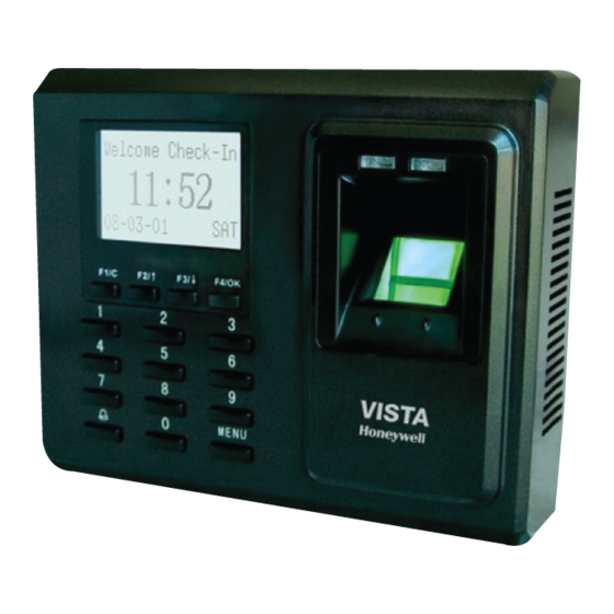
- Page 1 Fingerprint T&A Access Control System CA-FP-100F CA-FP-100FS User Guide Version 1 .0 : : : : Date : : : : F eb, 2012 © 2012 Honeywell International Inc. All rights reserved.
- Page 2 Content Introduced Content Introduced This document describes Honeywell VISTA Serials Access Control System installation user guide & wiring instruction. About this Guide The Honeywell VISTA Serials Access Control System User guide is designed to provide information to install the CA-FP-100F & CA-FP-100FS serial Access Control System, for operation and configuration, please refer to the corresponding user’s manual.
-
Page 3: Table Of Contents
Content Introduced Contents 1 Before Installing ................1 1.1 Notice about installing ............1 2 System Configuration ..............4 2.1 The illustration of system construction ......4 2.2 The sketch map of communication ........5 3.Installation .................. 6 3.1 Fixing mounting plate ............6 3.2 Connect with peripheral equipment ......... -
Page 4: Before Installing
Fingerprint T&A Access Control System User Guide 1 Before Installing 1.1 Notice about installing Access Control System is a mass-produced product. It strictly tested comply with the standard of China, U.S.A, and EU. This file contains important information. It is better for you to read it carefully prior to use. - Page 5 10. Before device to be connected please read and always follow "Quick connect Guide" closely. Because the wrong wiring will cause the core block and sensor to burn out, insult in device to break down, at this cause Honeywell is not liable for any damages and trouble.
- Page 6 Fingerprint T&A Access Control System User Guide 11. If the space between power adapters and device is too long, please do not use the twisted-pair or other type ferrules for the power wire. When the power wire is choused, you should consider attenuation of voltage, which has passed long distance transfer.
-
Page 7: System Configuration
Fingerprint T&A Access Control System User Guide 2 System Configuration 2.1 The illustration of system construction... -
Page 8: The Sketch Map Of Communication
Fingerprint T&A Access Control System User Guide The sketch map of communication 1, Access Control System directly connects with PC through RS232 or TCP/IP 2, Access Control System connects with PC through RS485 network 3, Access Control System connects with PC through TCP/IP network .... -
Page 9: Installation
Fingerprint T&A Access Control System User Guide 3. Installation 3.1 Fixing mounting plate Take out a Access Control System d ismantle the screw ① , between machine body and mounting plate until it is out, see figure (1). Carefully take up the bottom of mounting plate, see figure (2), ②... -
Page 10: Connect With Peripheral Equipment
Fingerprint T&A Access Control System User Guide 3.2 Connect with peripheral equipment Caution: Do not to connect peripheral equipment before the power of the device is cut down, otherwise it is possible to damage the device badly. Please follow instruction to connect peripheral equipment 1) Door sensor connection s ensor, GND (... - Page 11 Fingerprint T&A Access Control System User Guide RJ45-1 Alarm - Alarm + RJ45-2 RJ45-3 RJ45-6 Button Sensor Bell+ Bell- 232RX 232 TX +12V The definition of socket without Wiegand input 485 A 485 B BEEP GLED RLED +12V The definition of socket with Wiegand input Jump...
-
Page 12: Door Sensor
Fingerprint T&A Access Control System User Guide 3.2.1 Door Sensor The door sensor is used to detect the door open-close status, Access Control System can monitor if the door has been unauthorized open through the door sensor, at this time it can output a alarm signal, moreover, Access Control System can trigger prompt warning if after surpassing a timed period, the door still open. -
Page 13: Conntion With Lock
Fingerprint T&A Access Control System User Guide 3.2.4 Connection with lock The way of installing door lock depends on the type of lock and local condition. Internal resistor, which comes from long distance transfer, should be taken into consideration when selecting the cable of electric power. - Page 14 Fingerprint T&A Access Control System User Guide state change. Power Ground G ND C urrent loop ground ( ( ( ( ) ) ) ) , Input terminal of door sensor S ensor G ND t he input port of (...
- Page 15 Fingerprint T&A Access Control System User Guide when you install door lock, there are two thing you must think about, -- safety and security , in other words, do you want which result that is if lose control of this door, the door is still in safety—“lost control but safety”...
- Page 16 Fingerprint T&A Access Control System User Guide that the door of “lost control but security” will be installed in the area, which needs to be protected through fair and foul. One representative application of “ lost control but security” is to use electrical lock, if the power supply break off, the external personal is not able to open the door, but the internal person can open the by manual operation.
- Page 17 Fingerprint T&A Access Control System User Guide N C lock connection A ccess Control System and lock power by ( 、 one adapter together , Jump 2,3 pin closed ) Lock N O lock connection A ccess control System and lock powered (...
- Page 18 Fingerprint T&A Access Control System User Guide t he output relay signal by Access control System, NC lock 、 connection Access Control System and lock powered by ( independent adapters jump 1,2 closed ) Lock Lock Power t he output relay signal by Access control System, NO lock 、...
-
Page 19: Ethernet Connection
Fingerprint T&A Access Control System User Guide 3.2.5 Ethernet connection A ccess Control System connects with PC through cross cable ) A ccess Control System connects with PC through network and ) HUB to create a local network... - Page 20 Fingerprint T&A Access Control System User Guide 3) RJ45 plug wiring diagrams for Ethernet a) RJ45 plug standard b) Ethernet 10/100Base—T Crossover Cable mostly apply to HUB and Switch o r directly connect two Ethernet , terminals(not through HUB), fully support 10Base-T and 100Base-TX.
- Page 21 Fingerprint T&A Access Control System User Guide c) Ethernet 10/100Base-T Straight Thru Cable Support 10Base-T and 100Base-TX apply to connect with , network card and HUB o r network outlet s ometime it is called ( ) , (whips)” Wiring standard / Pin Color Pin / Wiring standard 1 <—...
-
Page 22: Connection With Rs232
Fingerprint T&A Access Control System User Guide 3.2.6 Connection with RS232 The definition of PC connection with Access Control System PC Serial Port Access Control System serial port Pin2-Rxd Pin5-Txd Pin3-Txd Pin4-Txd Pin5-Gnd Pin6-Gnd... - Page 23 Fingerprint T&A Access Control System User Guide 3.2.7 Connection with RS485 The definition of terminal connection Terminal Function Pin1-485A RS-485 communication + Pin2-485B RS-485 communication -...
-
Page 24: Wiegand Output
Fingerprint T&A Access Control System User Guide 3.2.8 Wiegand output Access Control System provide standard Wiegand 26 output, which can be connected to most of access controllers, like the way of connecting with a ID reader or password keyboard. The distance from the controller to device cannot be more than 15 meter (if the signal must be transferred much further or there is a strong interference around, please adopt a Wiegand signal... -
Page 25: Power Connection
Fingerprint T&A Access Control System User Guide 3.2.9 Power connection This device is powered by 12VDC. Its current is approximately 50mA in the ready work status and 400mA in the work status. The power is conducted along with the terminal; you can use the 12V-4A-supply adapter that is provided along with the device. -
Page 26: Fixing Access Control System
Fingerprint T&A Access Control System User Guide 3.3 Fixing Access Control System Confirm all connection plugs correctly. ① Align back iron-plate of Access Control System body to ② mounting plate properly, and push it up, see figure1, then push device backward, see figure 2. Turn and tie up the screw bottom. -
Page 27: Fastening Access Control System
Fingerprint T&A Access Control System User Guide 4. Fastening Access Control System After all system installation finished, make a test and examine prior to power on, inspect whether the lock driver is OK or not, for more details, please see “User Guide” and “Software Manual” t he green LED begins to glitter after power up. -
Page 28: Others
Fingerprint T&A Access Control System User Guide 5. Others 5.1 Reset Due to operation error or other accidence, which leads the machine not to work, you can restart machine through reset key. t ake a small tool which diameter is no more than 2mm. ①... -
Page 29: Cable Doorbell
Fingerprint T&A Access Control System User Guide 5.3 Cable doorbell There is a key which is remark as icon on the keypad , this ( ) key is used for doorbell. Door Bell Put the doorbell in the proper place, press the doorbell key on the device, please see circle marked, after the doorbell receive a signal, it will ring. - Page 30 Fingerprint T&A Access Control System User Guide...
- Page 31 Fingerprint T&A Access Control System User Guide Honeywell Security Group Automation & Control Solutions Honeywell International Inc. www.black.honeywell.com © 2012 Honeywell International Inc. All rights reserved.