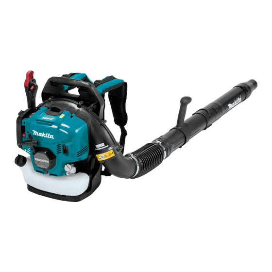
Makita EB5300TH Repair Manual
Petrol blower
Hide thumbs
Also See for EB5300TH:
- Original instruction manual (232 pages) ,
- Instruction manual (84 pages) ,
- Original instruction manual (84 pages)

Related Manuals for Makita EB5300TH


Summary of Contents for Makita EB5300TH
- Page 1 PETROL BLOWER EB5300TH (TUBE-MOUNTED THROTTLE) EB5300THG (TUBE-MOUNTED THROTTLE) EB5300WH (HIP-MOUNTED THROTTLE) REPAIR MANUAL April 2017 Ver.1...
-
Page 2: Table Of Contents
4-5-13 Connecting Control cable to Blower body (for Model EB5300WH) ............. 60 4-5-14 Connecting Control cable to Blower body (for Model EB5300TH) ............61 Key points of completion inspection ......................65 TIGHTENING TORQUE SPECIFICATIONS ....................... 66 CIRCUIT DIAGRAM ............................67 EB5300WH (Hip throttle model) ........................ -
Page 3: Safe Handling Of The Machine
SAFE HANDLING OF THE MACHINE Read the instruction manual of this product and follow the instructions for safe repair. Wear gloves. When the engine is hot from use, cool down the engine enough or you can get burned. ... -
Page 4: Gaskets And Lubrication
Gaskets and lubrication When you remove Gasket, be sure to remove gasket residue. When reassembling the machine, replace Gaskets with new ones. Use parts cleaner or the like to remove grease from the mating surface of Cylinder and Crankcase and then apply Liquid gasket ThreeBond 1215. - Page 5 When attaching Flywheel, use parts cleaner or the like to remove the grease from the tapered portion. Lubricant Amount Makita grease FA. No.2 a little 4-stroke engine oil a little Fig. 2 Outer circumference of Push rods Tips of valves and sliding...
-
Page 6: Repair Work
REPAIR WORK Before starting repair work 4-1-1 Draining fuel tank, removing Pipes and Nozzle Tips Remove Fuel tank cap assembly, and then Drain Carburetor as much as possible by pushing drain Fuel tank. Primer pump repeatedly. Drain the oil when the machine is disassembled down to Engine block. -
Page 7: Blower Section
Blower Section 4-2-1 Removing Band complete L/R and Cushion As for the REPAIR WORK of Cam gear, Muffler, Air cleaner plate, Carburetor, Insulator and Ignition coil, refer to 4-5-1. Fig. 6 Release Buckle [1] on Band complete from the top of Frame as follows: with a tool such as long-nose pliers, turn Buckle 90 degrees, then pull it out through the slot of Frame. -
Page 8: Removing Frame, Compression Spring 22 (Damper Spring), Fan 243 And Front Volute Case
4-2-2 Removing Frame, Compression spring 22 (Damper spring), Fan 243 and Front volute case Fig. 9 Remove Frame by removing six M5x16 Hex socket head bolts [1] as shown on the left. Note To prevent the engine section from falling down, put the machine on a workbench with the Recoil starter side down. - Page 9 Fig. 12 Remove four M6x25 Hex socket head bolts [1] to remove Fan 243 [2]. Fig. 13 Remove three M5x20 Hex socket head bolts [1] to remove Recoil starter [2]. Fig. 14 Remove five 5x20 Tapping screws [1] to remove Engine cover complete [2].
- Page 10 Fig. 16 Remove two 4x14 Tapping screws [2] fastening Control cable [1], and remove two Strain relieves [3]. Fig. 17 Loosen two M5x20 Thumb screws [1] to remove Air cleaner cover [2] and Air cleaner element [3]. Fig. 18 Remove Fuel tube 3-370 (black) [1] from Carburetor [2] with 1R311.
-
Page 11: Recoil Starter
Fig. 21 Remove six M6x25 Hex socket head bolts [1] to remove Front volute case [2]. Recoil starter 4-3-1 Disassembling Recoil starter Note Follow Fig. 13 to remove Recoil starter. Be sure to wear leather gloves to protect your hands. Fig. - Page 12 Fig. 25 Remove two Swing arms [1] from Collar [2]. 12 / 71...
-
Page 13: Disassembling/Assembling Of Spiral Spring
Hook the outer end of the spring into the notch [3] of Reel [2]. Rewind the spring. Tips When rewinding Spiral spring [1], keep pressing it down to prevent it from popping out. Apply Makita grease FA No.2 to the whole portion of Spiral spring. 13 / 71... -
Page 14: Assembling Recoil Starter
4-3-3 Assembling Recoil starter Fig. 28 Pass one end of Starter rope [1] through Starter knob [2] and Rope stopper [3], and then tie a knot in the end of the rope. Note Be sure to wear leather gloves to protect your hands. ... - Page 15 Fig. 31 Hook Starter rope [1] on the U-shaped notch of Reel [2], and then turn Reel [2] counterclockwise at least three turns to increase the tension on Spiral spring. Note Do not turn Reel [2] clockwise or Spiral spring will be deformed.
-
Page 16: Disassembling Fuel Tank
4-3-4 Disassembling Fuel tank Fig. 34 Remove Fuel tank cap assembly [1] and Tube guard 20-102 [2]. Note Be careful not to break Cap holder [3] of Fuel tank cap assembly [1]. Be sure to hook your finger on Cap holder [3], and then pull it out of Fuel tank. -
Page 17: Assembling Fuel Tank
4-3-5 Assembling Fuel tank Fig. 36 Pass Tubes through Grommet. 145mm 165mm Fig. 37 With a slotted screwdriver, assemble Grommet [1] to Fuel tank. Note The clear Tube should be placed to the fuel filler opening side, and all the three Tubes should be on the red dotted line. -
Page 18: Disconnecting Control Cable
4-3-6 Disconnecting Control cable Disconnect two Straight terminals and remove two Strain relieves. (Refer to Fig. 15 and Fig. 16.) Fig. 39 With a slotted screwdriver, pry up the locking tab to remove Carburetor cover [1]. Fig. 40 Turn Throttle [1] clockwise and hold it there with your finger. -
Page 19: Control Lever
Control lever 4-4-1 Disassembling Control lever (for Model EB5300TH) According to 4-1-1, remove M5x30 Thumb screw. Fig. 41 Remove five 4x18 Tapping screws [1] to remove Lever case R [2]. Fig. 42 Remove Throttle lever A [1] and Compression spring 4... - Page 20 Pull Control cable and Lead unit out of Corrugated tube. Tips First, pull out the wire of Control cable, and then one by one, pull out the two lead wires (with Straight terminal) of Lead unit. 20 / 71...
-
Page 21: Assembling Control Lever (For Model Eb5300Th)
4-4-2 Assembling Control lever (for Model EB5300TH) Fig. 45 Route Lead unit and Control cable [1] through Corrugated tube [2]. Tips Using vinyl tape or the like, attach the male straight terminal [4] of Lead unit to the back of the cover tube of the female straight terminal [3]. - Page 22 Fig. 47 Using 1R402-A, make sure that there is conduction when Control lever B [1] is set to “O”, and that there is no conduction when Control lever B [1] is set to ”I”. Tips By attaching 1R402-B to the tip of each probe of 1R402-A, you can do the check easily, with clipping the straight terminals with the probes.
-
Page 23: Disassembling Control Arm (For Model Eb5300Wh)
4-4-3 Disassembling Control arm (for Model EB5300WH) According to Fig. 39 and Fig. 40, remove Lead unit and Control cable. Fig. 48 Remove two 5x20 Tapping screws [1] to remove Arm base section [2] from Frame [3]. Fig. 49 Remove M6x25 Hex socket head bolt [1] to remove Arm [2] and Arm base section [3]. - Page 24 Fig. 52 Remove two Rubber sleeves 6 [2] from Arm base [1]. and then remove two Torsion springs 21 [3]. Fig. 53 Remove six 4x18 Tapping screws [1] to remove Arm cover [2]. Fig. 54 Disconnect the connector of Lead unit, and then push Switch unit [1] out of Arm cover [2] with 1R311.
- Page 25 Fig. 56 Remove M5x25 Hex socket head bolt [1] to remove Throttle lever [2]. In this step, Wave washer 20 [3] is also removed. Fig. 57 Using 1R402-A, make sure that there is conduction 1R402(-A) when Control lever is set to “O”, and that there is no conduction when Control lever is set to ”I”.
-
Page 26: Assembling Control Arm (For Model Eb5300Wh)
4-4-4 Assembling Control arm (for Model EB5300WH) Assemble Control arm by reversing the disassembly procedure. Fig. 58 The orientation of the two Torsion springs 21 [1] matters. Put the spring in the spring chamber of Arm base [2] with the short leg on the far side. Fit the long leg of Torsion spring 21 [1] in the depressed portion of Arm base holder [3], then assemble Arm base to Arm base holder. - Page 27 Fig. 59 Put the lead wires [4] of Switch unit in the space indicated by (a). Fix the lead wires [4] of Switch unit in the lead wire holders indicated by (b). The slack portion of the lead wires [4] of Switch unit should be put in the space indicated by (c).
-
Page 28: Engine Section
Engine section 4-5-1 Disassembling Engine The following parts can be disassembled from Engine section without removing Blower section: Cam gear, Muffler, Air cleaner plate, Carburetor, Insulator, Ignition coil. The following procedure is that the blower section is removed. According to Fig. 13 and Fig. 14, remove Recoil starter and Engine cover complete. Fig. -
Page 29: Disassembling Muffler
4-5-2 Disassembling Muffler Fig. 63 Remove M4x6 Pan head screw [1], and then remove Tail plate [2] and Spark arrester [3] out of Muffler. Tips If there are carbon deposits on Spark arrester [3], remove them with commercial carbon remover. 4-5-3 Assembling Muffler Assemble by reversing the disassembly procedure. -
Page 30: Disassembling Engine (Continued)
4-5-4 Disassembling Engine (continued) According to Fig. 17, remove Air cleaner cover and Air cleaner element. Fig. 64 Close the choke, and loosen two M5x50 Hex socket button head bolts [1]. Tips At this point, do not remove two M5x50 Hex socket button head bolts [1]. - Page 31 Fig. 66 Remove two M5x20 Hex socket head bolts [1], and remove Insulator [2]. With 1R311, remove Oil tube 5-195 [3] and Tube 5-55 [4] from Cylinder block. Fig. 67 Remove the following parts: 4x18 Tapping screw [1] Icing valve [2] ...
-
Page 32: Disassembling Carburetor
4-5-5 Disassembling Carburetor Fig. 68 Remove four Screws [1] to remove Metering diaphragm cover [2], Metering diaphragm [3], Metering diaphragm gasket [4], Pump body assembly [5], Inlet screen [6], Pump diaphragm [7] and Pump gasket [8]. Remove Conical compression spring 5-9 [9]. If Metering diaphragm [3] or Pump diaphragm [7] is deformed or hardened, replace it with a new one. -
Page 33: Assembling Carburetor
4-5-6 Assembling Carburetor Fig. 71 Assemble Carburetor by reversing the disassembly procedure. Clean up the parts with gasoline or the like, and then blow away the gasoline with air duster gun or the like. Note Do not blow air at a high pressure. If Pump diaphragm [3] and Metering diaphragm [5] are deformed/ hardened/ damaged/ corroded, replace them with new ones. - Page 34 Adjust screw [6], if Throttle of Carburetor does not move to the fully open/idle positions when you operate Throttle lever under the assembling-completed condition; in the case of EB5300TH, it indicates that Control lever is installed on Swivel pipe complete without twist in the cable.
-
Page 35: Disassembling Air Cleaner Plate
4-5-7 Disassembling Air Cleaner plate Fig. 72 Remove three 4x14 Tapping screws [1] to remove Rubber plate [2], Blowby guide [3], Choke plate [4] and Choke lever [5]. Fig. 73 With 1R311, squeeze the locking claws of Primer pump [1] to unlock from Cleaner case. Primer pump can now be removed. -
Page 36: Disassembling Engine (Continued)
4-5-9 Disassembling Engine (continued) Fig. 75 Remove two M4x20 Hex socket head bolts [1] to remove Ignition coil [2]. Tips Oil case [3] will interfere with removal of the bolt on the far side. So remove Oil case [3] or use an L-shaped hex wrench [4] to loosen the bolt. - Page 37 Fig. 77 For easy removal of Rod 2.5 from Rocker arm, position Piston at compression top dead center as 1R411 1R411 follows: Remove Spark plug and then insert 1R411 through the spark plug hole. Turn Flywheel [1] until Piston reaches the highest position.
- Page 38 Fig. 80 With 1R311, remove two Cam lifters [1] and Pin 5 1R311 [2]. Tips The left and right Cam lifters [1] are identical for easy assembling ; however, when assembling them to Pin 5 [2], be sure to install the one on your right first. Fig.
- Page 39 Fig. 84 Using 1R364, remove Flywheel [1]. Tips 1R364 Temporarily tighten Flange nut M10 [2] to protect the threads of Crankshaft. Fig. 85 Remove Spark plug CMR6H [1] with Box wrench Fig. 86 Remove four M5x20 Hex socket head bolts [1] to remove Oil case [2].
- Page 40 Fig. 88 Remove four M5x20 Hex socket head bolt [1] and four M6x20 Hex socket head bolt [2] to separate Crankcase [3] from Cylinder block. Fig. 89 Tips Crankcase [3] and Cylinder block [4] are securely joined together with liquid gasket. So, after removing the bolts, insert a slotted screwdriver into the gap of the mating face, and then turn the screwdriver to pry off Crankcase [3] from Cylinder block [4].
- Page 41 Fig. 91 With 1R311, remove one Check valve [1] from the 1R311 rocker chamber, and two Check valves [1] and Separator mesh [2] from the mating surface of Cylinder and Crankcase. Tips If Check valve [1] is deformed or damaged, or remains open, replace it with a new one.
- Page 42 Fig. 94 Remove the following parts: Retainer (2 pcs) [1], Compression spring 12 (2 pcs) [2], Exhaust valve [3], Intake valve [4]. Tips If Valve is contaminated, clean it up with a carbon remover. Rocker arm cannot be removed from Cylinder block because Rocker shaft is press-fitted into Cylinder block [5].
- Page 43 Fig. 98 Woodruff key 4 [1] can be removed by clamping it in a vise, then by pulling up Crankshaft [2]. 43 / 71...
-
Page 44: How To Use 1R181 Ignition Checker
4-5-10 How to use 1R181 Ignition checker Do not remove Spark plug. (It is necessary to check that sparks are certainly generated by pulling Starter rope even against the compressed air in Cylinder for normal use.) The conventional method to check directly for spark, with Spark plug attached on the outside of Cylinder, is uncertain and therefore prohibited. - Page 45 First, check that sparks are properly generated at startup of the engine. Plug cap Alligator clip Cylinder fin from Ignition coil Some products have this projection on the top. Ground terminal Spark gap adjusting knob High tension terminal (1) Attach Alligator clip onto Cylinder fin. (2) Set Spark gap adjusting knob to 6mm.
- Page 46 Next, check that sparks are properly generated while the engine is running. (description below contains only the differences from 1. This check is to determine whether engine stall/poor acceleration is caused by spark misfire or some other problem. You do not have to do this check, if sparks are properly generated in the startup check described in 1. * Set Spark gap adjusting knob to 4mm.
-
Page 47: Important Steps In Assembling Engine
4-5-11 Important steps in assembling Engine Assemble by reversing the disassembly procedure. Fig. 99 With 1R310 or the like, push in the following Check 1R310 valves [1] until they stop: One Check valve [1] on the rocker chamber Two Check valves [1] on the mating surface of Cylinder and Crankcase Fig. - Page 48 Fig. 102 Compress Compression spring 12 [2] by pushing in and holding Retainer [1] with 1R389 and 1R005. And then, with a slotted screwdriver or the like magnetized with 1R288, install Cotters [3] (Two Cotters are used for each Valve). 1R389 1R005 Fig.
- Page 49 Fig. 106 Apply a small amount of grease to each Oil seal 15 [1]’s contact surface with Crankshaft before installing Flat washer 35 [2] and Oil seal 15 [1] (Two different ones are used and the one on Key installation side has a larger outer diameter.) onto Crankshaft [3].
- Page 50 Fig. 110 Insert the assembly of Crankshaft [1] and Piston into Cylinder block [2]. Fig. 111 Carefully set Crankcase [1] on Cylinder block, and then fasten them by tightening four M6x20 Hex socket head bolts [2] and four M5x20 Hex socket head bolts [3] in numerical sequence as shown on the left.
- Page 51 Fig. 114 By tightening four M5x20 Hex socket head bolts [1], fasten Oil case [2] to Crankcase. Fig. 115 Temporarily tighten Flange nut M10 [1], then screw 1R372 1R372 into the spark plug hole by hand, and then turn Flywheel [2] until Piston stops. Note Remove any grease from the tapered portion of Crankshaft with parts cleaner.
- Page 52 Fig. 118 Remove 1R372, then insert 1R411 into the spark plug 1R411 hole, and then turn Flywheel [1] so that Piston is at top dead center. Check the back of Flywheel [1]. If Piston is at top dead center, the matching mark of two lines [2] is parallel with Cylinder block (Crankcase) [3].
- Page 53 Fig. 121 Insert Rod 2.5 (2 pcs) [1] from the hole of Cylinder head, and put the tip of the rod in the dimple of Cam lifter (2 pcs) [2]. Tips Apply a little amount of 4-stroke engine oil to the dimple [3] of Cam lifter (2 pcs) [2].
- Page 54 Turn Pulley an even number of times to bring Piston to the compression top dead center again, and then check the valve clearance. Tips When Fuel tank is installed on the engine, you cannot check the position of the matching mark. In this case, find compression top dead center as follows.
- Page 55 Fig. 127 Connect Tube 5-55 [1] and Oil tube 5-195 [2] to Cylinder block [3], then pass them through the corresponding holes of Insulator [4] and then connect Oil tube 5-195 [2] to Rocker cover [5]. [2] [5] Fig. 128 Fasten Insulator [2] to Cylinder block with M5x20 Hex socket head bolt (3 pcs) [1], and then hold Oil tube 5-195 [3] in the clamp [4] of Insulator [2].
- Page 56 Fig. 130 Push each Tube to Cylinder securely onto the nipple of each part until it stop. The clearance between them 1.0mm should be 1.0mm or less. Fig. 131 Install Exhaust port spacer [1] on Cylinder block [2]. Tips The orientation of Exhaust port spacer [1] does not matter. Fig.
- Page 57 Fig. 134 Using an L-shaped hex wrench, tighten two M4x20 Hex socket head bolts [1] to fasten Ignition coil [2] to Crankcase. Fig. 135 Pass High-voltage cable [1] through the hole of Insulator [2], and then install Spark plug cap [3] onto Spark plug CMR6H.
-
Page 58: Assembling Blower Section To Engine Section
4-5-12 Assembling Blower section to Engine section Fig. 136 By tightening six M6x25 Hex socket head bolts [1] and two Tapping screws [2], fasten Front volute case [3] to Cylinder block. Fig. 137 By tightening four M6x25 Hex socket head bolts [1], fasten Fan 243 [2] to Flywheel. - Page 59 Fig. 138 Fasten Rear volute case [2] to Front volute case by tightening ten 5x20 Tapping screws [3] so that Elbow [1] can be squeezed with the two volute cases. Fig. 139 Install four Compression springs 22 [1] on Rear volute case.
-
Page 60: Connecting Control Cable To Blower Body (For Model Eb5300Wh)
4-5-13 Connecting Control cable to Blower body (for Model EB5300WH) Fig. 141 Pass the cables through the hole of Frame [1], and then tighten two 5x20 Tapping screws [2] to fasten Arm base section [3] to Frame. Fig. 142 Pass the barrel nipple [1] of Control cable through Adjust screw. -
Page 61: Connecting Control Cable To Blower Body (For Model Eb5300Th)
4-5-14 Connecting Control cable to Blower body (for Model EB5300TH) Fig. 145 Pass the barrel nipple of Control cable through Adjust screw [1]. Then turn Throttle [2] clockwise and hold it with finger, and then attach the barrel nipple to Swivel [3]. - Page 62 Fig. 149 With 1R311, connect Fuel tube 3-85 (transparent) [1] and Fuel tube 3-370 (transparent) [2] to Primer pump [3], and Fuel tube 3-370 (black) [4] to Carburetor [5]. Note Push each Tube securely onto the nipple of each part until it stops.
- Page 63 Install Recoil starter with three M5x20 Hex socket head bolts. Attach Air cleaner element to Air cleaner case. Fasten Air cleaner cover to Air cleaner case by tightening two M5x20 Thumb screws securely until they are seated. Fig. 153 Install Cushion [2] onto Frame by pushing four Lock rivets [1] through Cushion into Frame.
- Page 64 Note Install Nozzle and Intermediate pipe (Long Be sure to check engine speed with 1R070, and with End pipe or Short pipe) on Swivel pipe. nozzle 90-62 (nozzle diameter: 61.5mm) on Intermediate pipe. Without the nozzle, engine speed cannot be increased.
-
Page 65: Key Points Of Completion Inspection
Carburetor does not move to the full throttle or idling position even though you operate Throttle lever in the condition of “assembly completed”, which indicates, in the case of Model EB5300TH, that Control lever is installed on Swivel pipe Adjust screw Carburetor with no twist in Control cable. -
Page 66: Tightening Torque Specifications
TIGHTENING TORQUE SPECIFICATIONS Tightening Q’ty torque Parts to fasten Fastener (N・m) M5x20 Hex socket head bolt 6.0 - 8.0 <=> Cylinder block Crankcase M6x20 Hex socket head bolt 10.0 - 12.0 <=> Crankcase Retainer plate M5x20 Hex socket head bolt 4.5 - 6.5 Drain bolt (aluminum washer) M8x12 Hex bolt... -
Page 67: Circuit Diagram
Circuit diagram of Switch Black/ Black/ AWG20 AWG20 Lead unit A Lead unit AWG: American wire gauge EB5300TH (Tube throttle model) Fig. 157 Ignition coil Lead unit B Lead unit A Leaf spring A or B Black/ Black/ AWG20... -
Page 68: Wiring Diagram
WIRING DIAGRAM Lever case or Arm section 7-1-1 EB5300TH (Tube throttle model) Fig. 158 Throttle lever should be installed as shown below. ←” I” ←” O” Throttle lever Fix the lead wires in these lead wire holders. Put Controller lead wires and Corrugated tube in these lead wire holders. -
Page 69: Eb5300Wh (Hip Throttle Model)
7-1-2 EB5300WH (Hip throttle model) Fig. 159 Fix the lead wires of Switch unit in these lead wire holders. Switch unit Switch terminal 1 Rib A The lead wires of Switch unit from Switch terminal 1 should be put in Rib A and the inner wall. Put Controller lead wires and Corrugated Rib B tube in this space. -
Page 70: Front Volute Case Section
Front volute case section Fig. 160 Lead unit A from Ignition coil should be The high-voltage cable should be deeply put into Lead wire holder A. Lead unit B from Ignition coil should be routed in this space. deeply put into Lead wire holder B. -
Page 71: Routing Of Corrugated Tube
7-2-1 Routing of Corrugated tube Fig. 161 EB5300TH: Corrugated tube should be put into this space. EB5300WH: Corrugated tube should be put into this space. 71 / 71...