Cisco IR1101 Hardware Installation Manual
Industrial integrated services router
Hide thumbs
Also See for IR1101:
- Hardware installation manual (47 pages) ,
- Manual (26 pages) ,
- User manual (26 pages)
Table of Contents
Advertisement
Quick Links
Advertisement
Table of Contents

Related Manuals for Cisco IR1101


Summary of Contents for Cisco IR1101
- Page 1 IR1101 Industrial Integrated Services Router Hardware Installation Guide First Published: 2018-07-04 Last Modified: 2019-12-04 Americas Headquarters Cisco Systems, Inc. 170 West Tasman Drive San Jose, CA 95134-1706 http://www.cisco.com Tel: 408 526-4000 800 553-NETS (6387) Fax: 408 527-0883...
- Page 2 © 2018–2019 Cisco Systems, Inc. All rights reserved.
-
Page 3: Table Of Contents
Cisco IR1101 Base Router Cisco IRM-1100-SPMI Expansion Module Cisco IR-1100-SP Expansion Module Cisco Pluggable Module mSATA Module Front Panel Icons and LEDs Memory Reset Button Supported Cisco Antennas and Antenna Accessories Modem Support Power Supply IR1101 Industrial Integrated Services Router Hardware Installation Guide... - Page 4 Installing the IRM-1100 Expansion Module Installing the IRM-1100 Expansion Module Items Shipped with your Expansion Module Installing the Expansion Module Mounting the IR1101 Router with the IRM-1100 Expansion Module Attached Mounting the Device Using Mounting Brackets IR1101 Industrial Integrated Services Router Hardware Installation Guide...
- Page 5 Serial Port Cable DB9 Adapter Side RJ-45 Adapter Side Verifying Connections C H A P T E R 7 Technical Specifications Technical Specifications Router Specifications IR1101 Base Unit IRM-1100 Expansion Unit EM74XX Modem Specifications IR1101 Industrial Integrated Services Router Hardware Installation Guide...
- Page 6 Contents IR1101 Industrial Integrated Services Router Hardware Installation Guide...
-
Page 7: Preface
The sections are: Objective This guide provides an overview and explains how to install and connect the Cisco IR1101. Audience This guide is intended for people who have a high level of technical ability, although they may not have experience with Cisco software. -
Page 8: Safety Warnings
Verfahren zur Vorbeugung vor Unfällen vertraut. Suchen Sie mit der am Ende jeder Warnung angegebe Anweisungsnummer nach der jeweiligen Übersetzung in den übersetzten Sicherheitshinweisen, die zusam mit diesem Gerät ausgeliefert wurden. BEWAHREN SIE DIESE HINWEISE GUT AUF. IR1101 Industrial Integrated Services Router Hardware Installation Guide... - Page 9 Använd det nummer som finns i slutet av varje varning för a dess översättning i de översatta säkerhetsvarningar som medföljer denna anordning. SPARA DESSA ANVISNINGAR IR1101 Industrial Integrated Services Router Hardware Installation Guide...
- Page 10 Brug erklæringsnumm efter hver advarsel for at finde oversættelsen i de oversatte advarsler, der fulgte med denne enhed. GEM DISSE ANVISNINGER IR1101 Industrial Integrated Services Router Hardware Installation Guide...
- Page 11 Preface Safety Warnings IR1101 Industrial Integrated Services Router Hardware Installation Guide...
- Page 12 Law prohibits the use of UL-certified cables (that have the “UL” shown on the code) for any other electrical devices than products designated by CISCO. The use of cables that are certified by Electrical Appliance and Material Safety Law (that have “PSE” shown on the code) is not limited to CISCO-designated products.
- Page 13 Only trained and qualified personnel should be allowed to install, replace, or service this equipment. Statement 1030 Warning Ultimate disposal of this product should be handled according to all national laws and regulations. Statement 1040 IR1101 Industrial Integrated Services Router Hardware Installation Guide...
-
Page 14: Related Documentation
Obtaining Documentation and Submitting a Service Request For information on obtaining documentation, submitting a service request, and gathering additional information, see the monthly What s New in Cisco Product Documentation , which also lists all new and revised Cisco technical documentation, at: http://www.cisco.com/en/US/docs/general/whatsnew/whatsnew.html... -
Page 15: Product Overview
Pluggable Modules that can be added. The Pluggable Module provides the flexibility of adding different interfaces to the IR1101 platform, for example, a cellular module. The IR1101 ISR also has an Expansion Module that adds key capabilities such as dual LTE Pluggables, mSATA SSD FRU, SFP, and Digital GPIO connections. -
Page 16: Sku Information
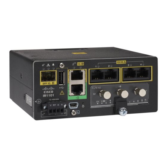
Product Overview SKU Information Figure 1: The IR1101 Industrial Integrated Services Router SKU Information Table 1 lists the different SKUs available for the Cisco IR 1101. Table 1: Supported SKUs for Cisco IR1101 SKU ID Description IR1101-K9 IR1101 Base Unit... -
Page 17: Cisco Ir1101 Series Platform Features
Cisco IR1101 Series Platform Features This section describes the different components of the router. Cisco IR1101 Base Router The following lists the hardware platform features for the Cisco IR1101. • External Power Entry • Nominal: 12 to 48VDC • Absolute min/max: 9.6 to 60VDC •... - Page 18 Cisco IR1101 Base Router Figure 2: Cisco IR1101 Industrial Integrated Services Router Figure 3 Figure 4 shows the IR1101 Base Module Front. Figure 3: Cisco IR1101 Integrated Services Router with USB covers in place Item Details USB 2.0 Port Cover Mini-USB Console Cover...
-
Page 19: Cisco Irm-1100-Spmi Expansion Module
Product Overview Cisco IRM-1100-SPMI Expansion Module Figure 4 shows the front panel details of the Cisco IR1101. Figure 4: Cisco IR1101 Front Panel SFP GE WAN Grounding Point (on side of device) USB 2.0 DC Power and Alarm Input RJ45 GE WAN... - Page 20 Product Overview Cisco IRM-1100-SPMI Expansion Module Figure 5: IR-1100-SPMI Expansion Module The following lists the hardware platform features for the Cisco IR-1100-SPMI: • 1 GE SFP (see the supported list of SFP’s here: SFP Module, page 26 • 1 Pluggable slot •...
- Page 21 The pinouts for the Digital I/O are described in Table 2 Table 2: Digital I/O Pinouts Pin # Name Direction Description DIO1 Digital IO 1 DIO2 Digital IO 2 DIO3 Digital IO 3 DIO4 Digital IO 4 IR1101 Industrial Integrated Services Router Hardware Installation Guide...
- Page 22 • Reverse voltage protected and causes no damage to the equipment. • Digital input and output can coexist on different channel. • LED Indicator: provision-able, On: Active, Off: Non-active. • Electrical isolation: 2000 VDC. • 4kV Surge protected (IEC 61000-4-5). IR1101 Industrial Integrated Services Router Hardware Installation Guide...
-
Page 23: Cisco Ir-1100-Sp Expansion Module
Pluggable LTE Module Highlights of the LTE Pluggable Module are: • All Cellular interfaces are supported through a Pluggable Module • Micro-Sim, 3FF size. Cisco recommends Industrial Temp micro SIMs that are rated from -40C to +105C. Figures Figure 8 Figure 9 show an example of a Pluggable Module. -
Page 24: Msata Module
(SSDs). The mSATA Pluggable Module plugs into the IR-1100-SPMI Expansion Module. Figure 10 shows the mSATA Pluggable Module. IR1101 Industrial Integrated Services Router Hardware Installation Guide... -
Page 25: Front Panel Icons And Leds
Amber Steady on — Power is OK but possible internal failure Red, Green, and Blue User Configurable Off — No VPN tunnel Steady Green — At least one VPN tunnel is up IR1101 Industrial Integrated Services Router Hardware Installation Guide... - Page 26 Grounding point (located on side of device) Reset Button DC Power Input (12V to 48V) DC Power Return Alarm Return Alarm IN Serial Ports Warning Expansion Module (Top or Left side) Expansion Module (Bottom or Right side) IR1101 Industrial Integrated Services Router Hardware Installation Guide...
-
Page 27: Memory
Product Overview Memory Memory The Cisco IR1101 uses flash memory and main memory. The flash memory contains the Cisco OS software image and the boot flash contains the ROMMON boot code. The memory includes: • 4 GB DRAM (soldered down) •... - Page 28 850-MHz (band 5 CLR), 850-MHz (bands 18 and 19 Low), 900-MHz (band 8), 1500-MHz (band 21), 1800-MHz (band 3), 2100-MHz (band 1), or 2600-MHz (band 7) networks; the multimode Cisco LTE Advanced 3.0 NIMs are backward-compatible with UMTS and DC-HSPA+: 800 MHz (band 19 Japan), 850 MHz (band 5), 850 MHz (band 6 Japan), 900 MHz (band 8), 1800 MHz (band 9), 2100 MHz (band 1), and TD-SCDMA 39.
-
Page 29: Power Supply
Power Supply Power Supply The Cisco IR1101 comes with an external DC power connector. The 4-pin power entry connector (receptacle) is mounted to the unit. The 4-pin power entry mating connector (plug) is attached to the receptacle. It is removed during installation and used to connect to the DC power source, then reattached to provide power to the unit. -
Page 30: Sfp Module
You can use any combination of the supported SFP modules listed in the table that follows. Note: The IR1101 is designed to operate in the Industrial temperature range (-40C to +85C internal component temperature range) and therefore cannot support commercial rated SFPs. - Page 31 Industrial 0C ~ +70C -5C ~ -40C ~ +85C +85C GLC-FE-100FX-RGD 2 km GLC-FE-100LX-RGD 10 km For the most up-to-date list of supported SFP models for Cisco Industrial Ethernet switches, see http://www.cisco.com/en/US/docs/interfaces_modules/transceiver_modules/compatibility/matrix/OL_6981.html#wp138176 IR1101 Industrial Integrated Services Router Hardware Installation Guide...
- Page 32 Product Overview SFP Module IR1101 Industrial Integrated Services Router Hardware Installation Guide...
-
Page 33: Installing The Router
C H A P T E R Installing the Router This chapter describes the equipment and the procedures for successfully installing the Cisco IR1101 ISR. There is a separate section for installing the IR1101 with an Expansion Module. • Installing the Router, on page 27 Installing the Router This chapter describes the equipment and the procedures for successfully installing the Cisco IR1101 ISR. -
Page 34: Equipment, Tools, And Connections
No antenna is shipped with the IR1101 by default. Items Shipped with your Router Unpack the box and verify that all items listed on the invoice were shipped with the Cisco IR1101. The following items are shipped with your router: •... -
Page 35: Mounting On A Wall, Table, Or Other Flat Surface
Mounting on a Wall, Table, or Other Flat Surface The Cisco IR1101 can be mounted in a vertical or horizontal orientation. It can be mounted to a wall or other flat surface, and can also be mounted to a DIN rail. - Page 36 Wall/Floor mounting hole dimensions with mounting brackets attached, on page 31 Figure 15: Wall/Floor mounting clearance and overall dimensions with mounting brackets attached, on page 32 for the dimensions of the mounting holes with the brackets attached to the router IR1101 Industrial Integrated Services Router Hardware Installation Guide...
- Page 37 Mounting on a Wall, Table, or Other Flat Surface Figure 14: Wall/Floor mounting hole dimensions with mounting brackets attached Four #10-32 screws are recommended when mounting the unit with these brackets attached to the neighboring Note surface. IR1101 Industrial Integrated Services Router Hardware Installation Guide...
-
Page 38: Installing A Din Rail
Figure 15: Wall/Floor mounting clearance and overall dimensions with mounting brackets attached Step 5 Route the cables so that they do not put a strain on the connectors or mounting hardware. Installing a DIN Rail The DIN Rail kit is ordered separately. IR1101 Industrial Integrated Services Router Hardware Installation Guide... -
Page 39: Mounting The Din Rail Bracket On The Router
Mounting the DIN Rail Bracket on the Router Note The DIN Rail can be installed on the Base IR1101 in two different orientations, horizontally and vertically. If the Base IR1101 has an Expansion Module attached, horizontal DIN mounting is not supported. -
Page 40: Attaching The Bracket Onto The Din Rail
Once the bracket is attached to the router, it can be mounted onto the DIN Rail. Attaching the Bracket onto the DIN Rail To attach the Cisco IR101 with the bracket to a DIN rail, follow these steps. Refer to the following figure for details. - Page 41 To remove the router from the DIN Rail, simply reverse the procedure. What to do next Note The procedure to attach the unit to the rail is the same with both orientations. IR1101 Industrial Integrated Services Router Hardware Installation Guide...
-
Page 42: Installing The Router Ground Connection
To install the ground connection, follow these steps: Step 1 Locate the grounding lug (1) attached to the side of the Cisco IR1101. It will be attached underneath two screws. Remove the screws holding it to the router and set it aside for reuse. -
Page 43: Pluggable Module
Pluggable Module remove and replace option is shown. The IR1101 may have a blank plate covering the Pluggable Module slot. This will need to be removed prior to installing the cellular modem module. The following example shows the LTE Pluggable Module. - Page 44 Prepare the cellular modem module by inserting the micro sims applicable for your modems into the device. Remove the screw (1) holding the access plate in place that covers the sim slots. It is located on the side of the module, as shown in . IR1101 Industrial Integrated Services Router Hardware Installation Guide...
- Page 45 Install your sims as shown in Figure 22: Sim Installation, on page 39. Make note of the proper slot number and sim orientation. Figure 22: Sim Installation Item Description Micro SIMs SIM 0 (towards the device) IR1101 Industrial Integrated Services Router Hardware Installation Guide...
- Page 46 Tighten the latch lock screw to a torque of 2.8 to 3.8 inch-lbs (0.3 to 0.4 newton meter). Refer to Figure 24: USB Cover Finished Installation, on page 41 for a finished USB cover installation. IR1101 Industrial Integrated Services Router Hardware Installation Guide...
- Page 47 (1) aligns with the screw hole (2) on the front of the device. Push the Pluggable Module all the way into the device until you feel it seat, and then torque the latch lock screw 8-10 inch-pound (0.9 to 1.1 newton meter). IR1101 Industrial Integrated Services Router Hardware Installation Guide...
- Page 48 Step 10 If no antennas are being installed on a port, make sure the caps are installed on the connector. IR1101 Industrial Integrated Services Router Hardware Installation Guide...
-
Page 49: Antenna Selection And Installation
Antenna Selection and Installation NOTE: Before you install the Cisco IR1101 Integrated Services Router on a table, wall, or DIN rail, install the antennas on the Pluggable Module. It is difficult to install the antennas after the router is installed. - Page 50 P-LTE-US or P-LTEA-EA pluggable modules on certain carriers, ensure that both Main and Aux cellular antennas are physically separated from the IR1101 chassis by a minimum of 5 feet (1.5 meters). This note only affects P-LTE-xx receiver operation in Band 5 in a narrow 875 MHz frequency range. No significant effect on the P-LTE-xx cellular Band 5 receiver has been measured when antennas are separated from the chassis by more than 5 feet (1.5 meters).
-
Page 51: Supported Antennas For The Ir1101
1.5 dBi 698-960 MHz 2G/3G/4G Cellular (ANT-4G-OMNI-OUT-N). 2 dBi 1448-1511 MHz Outdoor Omnidirectional Antenna for 2G/3G/4G 3.5 dBi 1710-2700 MHz Cellular antenna is designed to cover domestic LTE700/Cellular/PCS/AWS/MDS, WiMAX 2300/2500, and GSM900/GSM1800/UMTS/LTE2600 bands. IR1101 Industrial Integrated Services Router Hardware Installation Guide... -
Page 52: Gps/Gnss Antennas
LTE-ANTM-SMA-D antennas have high standalone efficiency, and maintain high efficiency when directly installed on front plate of a small or medium size Cisco router. However, depending on chassis size and a variety of other electromagnetic considerations, installing the antenna directly on the chassis is not always recommended. -
Page 53: Supported Rf Cables For The Ir1101
The 4G-LTE-ANTM-O-3-B integrated GPS RF front end is designed to reject collocated RF interference. Supported RF Cables for the IR1101 The following tables provide information for the cables supported by the IR1101: • Table 13: N(m) to N(m) RF cables, on page 47 •... - Page 54 CAB-L240-20-SM-TM SMA(m)-STR to TNC(m)-STRLMR-240, 20ft RF 1.5 dB @ 0.7 GHz1.8 dB @ 1.0 GHz2.4 dB @ 1.7 cableType: outdoor DB (direct burial) GHz2.9 dB @ 2.4 GHz3.1 dB @ 2.7 GHz IR1101 Industrial Integrated Services Router Hardware Installation Guide...
-
Page 55: Cellular Antenna Extension Bases
Antenna Selection and Installation Cellular Antenna Extension Bases Cellular Antenna Extension Bases The following table provide information for the Extension Bases supported by the IR1101. Table 17: Extension Bases Extension Base PID Description RF Loss 4G-AE010-R TNC(m)-STR to TNC(f)-STRLMR-195, 10 foot RF 1.1 dB @ 0.7 GHz 1.4 dB @ 1.0 GHz 1.8 dB @ 1.7... - Page 56 Antenna Selection and Installation Accessories IR1101 Industrial Integrated Services Router Hardware Installation Guide...
-
Page 57: Installing The Irm-1100 Expansion Module
To attach the IRM-1100 to the IR1101, perform the following steps: Step 1 Remove the protective cover from the mating connector on the IR1101 by unscrewing the two Phillips head screws. Refer Figure 26: Protective Cover, on page IR1101 Industrial Integrated Services Router Hardware Installation Guide... - Page 58 Installing the Expansion Module Figure 26: Protective Cover Step 2 After removing the protective connector cover from the IR1101, carefully align the Expansion Module to the IR1101 so that both mating connectors engage. See Figure 27: Mounting the Expansion Module, on page 53.
- Page 59 Step 3 Tighten the screws to a torque of 13-15 in. lbs (1.5-1.7) newton meter). When complete, the two devices form a single assembly as shown in Figure 28: Completed Assembly, on page IR1101 Industrial Integrated Services Router Hardware Installation Guide...
-
Page 60: Mounting The Ir1101 Router With The Irm-1100 Expansion Module Attached
Figure 28: Completed Assembly Mounting the IR1101 Router with the IRM-1100 Expansion Module Attached After the Cisco IRM-1100 is attached to the IR1101, it can be mounted in the following ways: • On a DIN Rail • Using mounting brackets Note: For the remainder of these instructions, we will refer to the combined IR1101/IRM-1100 as the “Device”. - Page 61 To mount the Device on a wall or other flat surface, follow these steps: Step 1 Attach the mounting brackets to the bottom of the Device. Refer to Figure 31: Mounting Brackets, on page 56 for guidance. IR1101 Industrial Integrated Services Router Hardware Installation Guide...
- Page 62 Figure 32: Wall/Floor mounting hole dimensions with mounting brackets attached, on page 57 Figure 33: Wall/Floor mounting clearance and overall dimensions with mounting brackets attached, on page 58 the dimensions of the mounting holes with the brackets attached to the Device. IR1101 Industrial Integrated Services Router Hardware Installation Guide...
- Page 63 Mounting the Device Using Mounting Brackets Figure 32: Wall/Floor mounting hole dimensions with mounting brackets attached Note: Four #10-32 screws are recommended when mounting the Device with these brackets attached to the neighboring surface. IR1101 Industrial Integrated Services Router Hardware Installation Guide...
-
Page 64: Installing A Din Rail
The DIN Rail kit is ordered separately. The Device can only be mounted vertically, with the ground lug on the bottom side as shown in Installing a DIN Rail, on page Figure 34: Device Orientation IR1101 Industrial Integrated Services Router Hardware Installation Guide... -
Page 65: Mounting The Din Rail Bracket On The Device
Step 2 Attach the IR1101 DIN mounting bracket (1) to the Device using the two screws (3) provided in the kit. Position the bracket over the two mounting holes, then use 13-15 in. lbs. (1.5-1.7 newton meter) of torque to screw the bracket onto the Device. - Page 66 Device so that the top hook of the DIN clips (1) clamps to the top section of DIN rail (2). Step 3 To remove the Device from the DIN Rail, simply reverse the procedure. IR1101 Industrial Integrated Services Router Hardware Installation Guide...
-
Page 67: Pluggable Module
Pluggable Module The Pluggable Module provides the IRM-1100 with a number of different configuration options. The installation of the Pluggable Module into the Expansion Module is the same as installing it into the IR1101. See that section at Pluggable Module, on page... - Page 68 I/O is input, the open-collector is open (off). Further details on the Digital I/O connector can be found at Digital I/O Connector, on page Wiring the Alarm Connections To wire the alarm connections on your Cisco IR1101 Expansion Module, follow these steps: Step 1 Locate the alarm connector on the router front panel.
-
Page 69: Installing The Msata Ssd
Mini-SATA, or mSATA, is a low-profile interface connector that enables more effective Serial ATA (SATA) integration in small form-factor drives roughly the size of a business card, such as solid state disks (SSDs). This section provides an overview of the mSATA SSD available for the Cisco IRM-1100 Expansion Module. mSATA Installation Instructions Note: Ensure that you are using proper static discharge techniques such as a wrist strap and static mat. - Page 70 After the module is properly inserted, tighten the module plate to the IRM-1100-SPMI with the two screws (2). The screws should be torqued to 2-3 in-lb (0.2-0.3 newton meter). Step 4 The installation is now complete. IR1101 Industrial Integrated Services Router Hardware Installation Guide...
-
Page 71: Connecting The Router
C H A P T E R Connecting the Router This chapter describes how to connect the IR1101 to Ethernet devices and a network. The chapter contains the following sections: • Connecting the Router, on page 65 Connecting the Router This chapter describes how to connect the IR1101 to Ethernet devices and a network. -
Page 72: Gui-Centric Task Template
60 VDC minimum, 5A maximum. Statement 1005 Warning Connect the unit only to DC power source that complies with the safety extra-low voltage (SELV) requirements in IEC 60950 based safety standards. Statement 1033 IR1101 Industrial Integrated Services Router Hardware Installation Guide... -
Page 73: Plugs And Pin-Outs
Install only in accordance with national and local wiring regulations. Statement 1045 Plugs and Pin-Outs The IR1101 ships with a DC power accessory kit. The power entry receptacle is on the IR1101. The pin-outs are shown in the following figure. Figure 42: Power Connector Pin-outs Table 20: Power connector Descriptions... - Page 74 Remove the two captive screws that attach the power and alarm connector to the router, and remove the connector. IR1101 Industrial Integrated Services Router Hardware Installation Guide...
-
Page 75: Serial Port Cable
Serial Port Cable One of the more common causes for tech support calls to Cisco is improper pinouts for serial port cables. This section will describe the different components that make up the serial cabling for the IoT routers. -
Page 76: Db9 Adapter Side
A common cause of confusion when building a connector is the perspective of how you are viewing the pinouts. The pinouts are different from the male versus female views when building the connector. See Figure 45: DB9 Pinout Views, on page IR1101 Industrial Integrated Services Router Hardware Installation Guide... -
Page 77: Rj-45 Adapter Side
The RJ-45 female side of the connector, as previously mentioned, has fixed wires on the connector. Refer to Figure 46: RJ-45 Female Pinouts, on page 72 for the pinouts, as well as the wire colors. Note: White can also be Gray, depending on the adapter manufacturer. IR1101 Industrial Integrated Services Router Hardware Installation Guide... - Page 78 DB9 side of the connector. This is done with the use of a pinning tool. An example of a common pinning tool is found in Figure 47: Pinning Tool, on page IR1101 Industrial Integrated Services Router Hardware Installation Guide...
- Page 79 Table 21: RJ45 to DB9 Male Adapter, on page 73 Table 22: RJ45 to DB9 Female Null Modem Adapter, on page Table 21: RJ45 to DB9 Male Adapter RJ-45 Wire Color Pins Pins Blue Orange Black Green IR1101 Industrial Integrated Services Router Hardware Installation Guide...
- Page 80 Place the pins into their proper sockets using the pinning tool, and when that is complete you should have a connector that looks similar to the picture in Figure 48: Completed Pinning, on page IR1101 Industrial Integrated Services Router Hardware Installation Guide...
- Page 81 Figure 48: Completed Pinning Snap the DB9 side of the adapter into place on the plastic connector holding the RJ-45 side of the connector. When this is complete, your connector is ready to use. IR1101 Industrial Integrated Services Router Hardware Installation Guide...
-
Page 82: Verifying Connections
To verify that all devices are properly connected to the router, first turn on all the connected devices, then check the LEDs. To verify router operation, refer to the Front Panel Icons and LEDs, on page IR1101 Industrial Integrated Services Router Hardware Installation Guide... -
Page 83: Technical Specifications
C H A P T E R Technical Specifications This appendix provides router, port, cabling specifications, and power adapters for the IR1101. • Technical Specifications, on page 77 Technical Specifications This appendix provides router, port, cabling specifications, and power adapters for the IR1101. -
Page 84: Irm-1100 Expansion Unit
16 hours)NOTE: This product has been safety certified up to 60°C maximum Note: See EM74XX Modem Specifications, on ambient.-500 to 5,000 feet. Derate max operating temperature 1.5°C per 1000 page 79 for the EM74XX Series Modems. feet. Humidity 10 – 95% IR1101 Industrial Integrated Services Router Hardware Installation Guide... -
Page 85: Em74Xx Modem Specifications
EM74XX series will experience reduced (throttled) performance in conditions where the ambient temperature reaches high levels. Refer to the following table for details on temperature/airflow and performance throughput. Table 25: Specifications for the IR1101 and IRM-1100 with EM74XX Series Modems Maximum Ambient Temperature (C/F) - Page 86 Technical Specifications EM74XX Modem Specifications IR1101 Industrial Integrated Services Router Hardware Installation Guide...