Table of Contents
Advertisement
Quick Links
Quick Start Guide for Cisco 910 Industrial Routers
Quick Start Guide for Cisco 910 Industrial
Routers
78-21635-01C0
Overview, page 2
Accessories, page 3
Ports, page 4
LED Definition, page 5
Installation of the Device, page 9
Resetting to Factory Mode, page 20
FCC Class A Notices and Warnings, page 20
RF Exposure Safety Notice, page 20
Regulatory Standards Compliance, page 23
For More Information, page 24
This guide describes how to quickly install the Cisco 910 Industrial Router.
For configuration information, see the Cisco 910 Industrial Router documentation on Cisco.com. For system
requirements, important notes, limitations, open and resolved bugs, and documentation updates, see the release notes
on Cisco.com.
Before installing, configuring, or upgrading the Cisco 910 Industrial Router, refer to the Release Notes for the latest
information.
Note:
If you are using the 3G models of Cisco 910 Industrial Routers, the Mobile Equipment Identifier (MEID), International
Mobile Equipment Identity (IMEI), and Electronic Serial Number (ESN) are necessary for you to set up the 3G interface to
be used for your service provider carriers. You can use the show cellular unit all command to display MEID, IMEI, and
ESN information. For more information, see the "Monitoring Cellular 3G Information" section in Chapter 20, Configuring
Cellular 3G Setting, of the Cisco 910 Industrial Router Software Configuration Guide.
1
Advertisement
Table of Contents

Related Manuals for Cisco 910 Series


Summary of Contents for Cisco 910 Series
-
Page 1: Table Of Contents
For configuration information, see the Cisco 910 Industrial Router documentation on Cisco.com. For system requirements, important notes, limitations, open and resolved bugs, and documentation updates, see the release notes on Cisco.com. Before installing, configuring, or upgrading the Cisco 910 Industrial Router, refer to the Release Notes for the latest information. Note:... -
Page 2: Overview
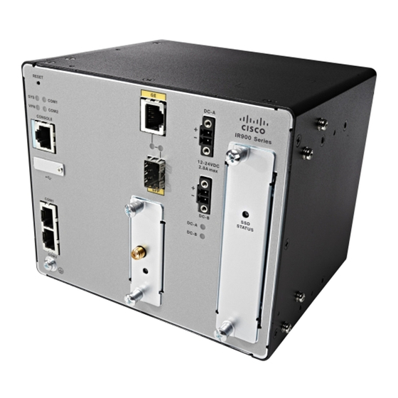
Quick Start Guide for Cisco 910 Industrial Routers Overview Overview The Cisco 910 Industrial Router is available in following models: IR910-K9, IR910G-K9/IR910G-NA-K9, and IR910W-K9 (Figure 1). IR910-K9 supports only the Ethernet combo uplink, IR910W-K9 supports both Wi-Fi and Ethernet combo uplink. -
Page 3: Accessories
Quick Start Guide for Cisco 910 Industrial Routers Accessories Accessories This section describes the basic model accessory kit contents of the Cisco 910 Industrial Router package, and configurable items, spares, and options. Package Contents Figure 2 shows the accessories of the three basic models of the Cisco 910 Industrial Router:... -
Page 4: Ports
All the configurable items, spares, and options should be purchased individually, and are not included by default with the Cisco 910 Industrial Router. Verify that you have received the items you have purchased. If any item is missing or damaged, contact your Cisco representative or reseller. -
Page 5: Led Definition
Quick Start Guide for Cisco 910 Industrial Routers LED Definition LED Definition Figure Figure 4, and Figure 5 show the positions of LEDs on the panel of each model. For detailed LED definitions, see Table Figure 3 LEDs of IR910-K9... - Page 6 Quick Start Guide for Cisco 910 Industrial Routers LED Definition Figure 4 LEDs of IR910W-K9...
- Page 7 Quick Start Guide for Cisco 910 Industrial Routers LED Definition Figure 5 LEDs of IR910G-K9/IR910G-NA-K9...
- Page 8 Quick Start Guide for Cisco 910 Industrial Routers LED Definition Table 3 shows the color and meaning of each LED. Table 3 LED Definition Single/Dual Color Meaning Color Dual System is not powered on or CPU has not completed boot up.
-
Page 9: Installation Of The Device
For detailed installation procedure, see Mounting Kit Assembly Guide for Cisco 910 Industrial Router. Before You Begin Before installing a Cisco 910 Industrial Router, verify that these guidelines are met: — Sufficient front clearance is available so that the LEDs can be seen. —... - Page 10 Caution: Be aware of the size and weight of the Cisco 910 Industrial Router when mounting. Ensure that the mounting location has a stable flat surface and can safely support the weight of the device.
- Page 11 Quick Start Guide for Cisco 910 Industrial Routers Installation of the Device Mounting to a DIN Rail for Indoor Use For indoor use, DIN rail mount is the default mounting solution. Figure 6 shows the mounting of the device to a standard 7.5-mm DIN rail.
- Page 12 Quick Start Guide for Cisco 910 Industrial Routers Installation of the Device Indoor Antenna Installation Follow these steps to install the 3G antenna for IR910G-K9/IR910G-NA-K9, or Wi-Fi antenna for IR910W-K9, for indoor use: Use two M3 screws to fix the antenna on the chassis, as shown in...
- Page 13 Quick Start Guide for Cisco 910 Industrial Routers Installation of the Device Place the antenna clip in the approximate location, as shown in Figure Figure 8 Positioning the Antenna Clip 3G antenna Wire clip Wi-Fi antenna Sensor card antenna Use the clip to fix the cable.
- Page 14 Quick Start Guide for Cisco 910 Industrial Routers Installation of the Device Mounting to a Wall or a Pole for Outdoor Use You can use IP55 enclosure and the wall/pole mount kit to mount the device to a wall or a pole for outdoor use.
- Page 15 Quick Start Guide for Cisco 910 Industrial Routers Installation of the Device Figure 10 IP55 Enclosure Antenna Installation 2 x M3, L14 (mm) screws Sensor card antenna Wi-Fi antenna 3G model in IP55 case Wi-Fi model in IP55 case 3G antenna...
- Page 16 Quick Start Guide for Cisco 910 Industrial Routers Installation of the Device Figure 11 External Antenna Cable Routing 3G or Wi-Fi antenna cable Wi-Fi antenna Sensor card antenna cable 3G antenna Sensor card antenna Mounting to a Wall Figure 12 Figure 13 show the wall mounting of the device.
- Page 17 Quick Start Guide for Cisco 910 Industrial Routers Installation of the Device Figure 12 Mounting to a Wall IP55 case assembly 4 x Wall mount screws Sheet metal wall and pole mount bracket 4 x Fasten screws Figure 13 Wall-Mounting Bracket Feature...
- Page 18 Quick Start Guide for Cisco 910 Industrial Routers Installation of the Device Pole Mounting Figure 14 Figure 15 show the pole mounting of the device. Figure 14 Mounting to a Pole IP55 case assembly 2 x Band straps Sheet metal wall and pole mount bracket...
-
Page 19: Powering On And Logging In To The System
Powering On and Logging In to the System The Cisco 910 Industrial Router supports dual DC power inputs. The voltage range can be from 12 VDC to 24 VDC. When the device is installed in an environment requiring AC inputs, use the optional AC power adapter listed in... -
Page 20: Resetting To Factory Mode
— No parity — None (flow control) Connect the power of the Cisco 910 Industrial Router to an AC/DC power adapter. The PC or terminal displays the bootloader sequence. Press Enter to display the setup prompt. Resetting to Factory Mode To reboot the entire system, press the Reset button and release it immediately. -
Page 21: Declaration Of Conformity With Regard To The Eu Directive 1999/5/Ec (R&Tte Directive)
This declaration is only valid for configurations (combinations of software, firmware and hardware) provided and/or supported by Cisco Systems for use within the EU or countries that have implemented the EU Directives. The use of software or firmware not supported/provided by Cisco Systems may result that the equipment is no longer compliant with the regulatory requirements. - Page 22 Quick Start Guide for Cisco 910 Industrial Routers Declaration of Conformity with Regard to the EU Directive 1999/5/EC (R&TTE Directive) Nederlands Dit apparaat voldoet aan de essentiele eisen en andere van toepassing zijnde bepalingen van de [Dutch]: Richtlijn 1999/5/EC. Malti...
-
Page 23: Regulatory Standards Compliance
Quick Start Guide for Cisco 910 Industrial Routers Regulatory Standards Compliance Regulatory Standards Compliance This section includes all the regulatory, safety, and FCC standards. Table 4 Regulatory Standards Compliance for the Cisco 910 Industrial Routers Specification Model No. Description Safety... -
Page 24: For More Information
Cisco and the Cisco logo are trademarks or registered trademarks of Cisco and/or its affiliates in the U.S. and other countries. To view a list of Cisco trademarks, go to this URL: www.cisco.com/go/trademarks. Third-party trademarks mentioned are the property of their respective owners. The use of the word partner does not imply a partnership relationship between Cisco and any other company.