Cisco IR829 Hardware Installation Manual
Integrated services router
Hide thumbs
Also See for IR829:
- Product manual (16 pages) ,
- Hardware installation manual (56 pages) ,
- Hardware installation manual (69 pages)
Table of Contents
Advertisement
Advertisement
Table of Contents

Related Manuals for Cisco IR829


Summary of Contents for Cisco IR829
- Page 1 Cisco IR829 Integrated Services Router Hardware Installation Guide August 2015 Americas Headquarters Cisco Systems, Inc. 170 West Tasman Drive San Jose, CA 95134-1706 http://www.cisco.com Tel: 408 526-4000 800 553-NETS (6387) Fax: 408 527-0883 Text Part Number:...
- Page 2 OR ITS SUPPLIERS HAVE BEEN ADVISED OF THE POSSIBILITY OF SUCH DAMAGES. Cisco and the Cisco logo are trademarks or registered trademarks of Cisco and/or its affiliates in the U.S. and other countries. To view a list of Cisco trademarks, go to this URL: www.cisco.com/go/trademarks.
-
Page 3: Table Of Contents
C O N T E N T S Cisco IR829 Integrated Services Router Hardware Installation Guide Product Overview C H A P T E R General Description LEDs Memory SKU Information Hardware Features Platform Features for Cisco IR829 Reset Button... - Page 4 Configuring Guest OS Interface on Cisco IOS Enabling Guest OS Console Configuring Guest OS Starting Guest OS Accessing Guest OS Console Setting the Root Password Enabling Remote SSH Access Configuring NAT Troubleshooting Checking Connectivity Related Documentation Cisco IR829 Integrated Services Router Hardware Installation Guide...
- Page 5 Contents Technical Specifications C H A P T E R Router Specifications Cisco IR829 Integrated Services Router Hardware Installation Guide...
- Page 6 Contents Cisco IR829 Integrated Services Router Hardware Installation Guide...
- Page 7 This guide provides an overview and explains how to install, connect, and perform initial configuration for the Cisco IR829. Audience This guide is intended for people who have a high level of technical ability, although they may not have experience with Cisco software. Cisco 829 Integrated Services Router Hardware Installation Guide...
- Page 8 Means the following information will help you solve a problem. The tip information might not be troubleshooting or even an action, but could be useful information. Cisco 829 Integrated Services Router Hardware Installation Guide...
-
Page 9: Safety Warnings
éviter les accidents. Pour prendre connaissance des traductions des avertissements figurant dans les consignes de sécurité traduites qui accompagnent cet appareil, référez-vous au numéro de l'instruction situé à la fin de chaque avertissement. CONSERVEZ CES INFORMATIONS Cisco 829 Integrated Services Router Hardware Installation Guide... - Page 10 Al final de cada advertencia encontrará el número que le ayudará a encontrar el texto traducido en el apartado de traducciones que acompaña a este dispositivo. GUARDE ESTAS INSTRUCCIONES Cisco 829 Integrated Services Router Hardware Installation Guide...
- Page 11 Använd det nummer som finns i slutet av varje varning för att hitta dess översättning i de översatta säkerhetsvarningar som medföljer denna anordning. SPARA DESSA ANVISNINGAR Cisco 829 Integrated Services Router Hardware Installation Guide...
- Page 12 Brug erklæringsnummeret efter hver advarsel for at finde oversættelsen i de oversatte advarsler, der fulgte med denne enhed. GEM DISSE ANVISNINGER Cisco 829 Integrated Services Router Hardware Installation Guide...
- Page 13 Preface Cisco 829 Integrated Services Router Hardware Installation Guide...
- Page 14 Appliance and Material Safety Law prohibits the use of UL-certified cables (that have the “UL” shown on the code) for any other electrical devices than products designated by CISCO. The use of cables that are certified by Electrical Appliance and Material Safety Law (that have “PSE” shown on the code) is not limited to CISCO-designated products.
- Page 15 Ultimate disposal of this product should be handled according to all national laws and regulations. Statement 1040 Warning The covers are an integral part of the safety design of the product. Do not operate the unit without the covers installed. Statement 1077 Cisco 829 Integrated Services Router Hardware Installation Guide...
- Page 16 Obtaining Documentation and Submitting a Service Request For information on obtaining documentation, submitting a service request, and gathering additional information, see the monthly What’s New in Cisco Product Documentation, which also lists all new and revised Cisco technical documentation, at: http://www.cisco.com/en/US/docs/general/whatsnew/whatsnew.html...
-
Page 17: Product Overview
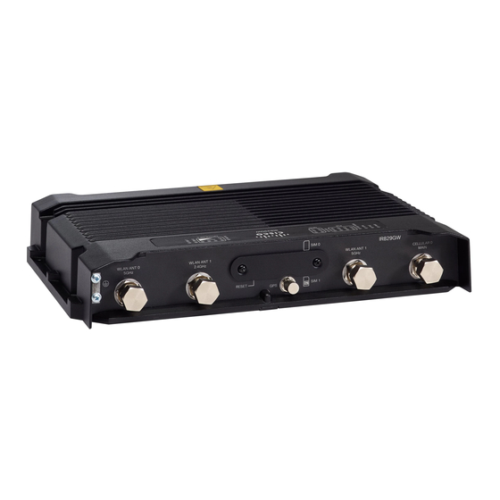
C H A P T E R Product Overview This chapter provides an overview of the features available for the Cisco IR829 Integrated Services Routers (ISRs) and contains the following sections: General Description, page 1-1 • SKU Information, page 1-6 •... - Page 18 Chapter 1 Product Overview General Description Figure 1-2 shows the front panel details of the Cisco IR829. Figure 1-2 Cisco IR829 Front Panel CELLULAR 0 AUX Serial Ports Limited Modularity Slot USB-A Port Gigabit WAN Power Input, Battery, and Ignition connector.
-
Page 19: Chapter 1 Product Overview
Chapter 1 Product Overview General Description Figure 1-4 Behind the SIM Door Figure 1-5 shows the top of the Cisco IR829. Figure 1-5 Cisco IR829 Top Cover Figure 1-6 shows the LED detail. Cisco IR829 Integrated Services Router Hardware Installation Guide... -
Page 20: Leds
Product Overview General Description Figure 1-6 Cisco IR829 LED Detail The following section shows a detailed description of the LEDs. LEDs The following table describes the LEDs for the Cisco IR829. Table 1-1 LED Descriptions Activity Description Power Status Off — No power Green Steady on —... - Page 21 Off — No USIM SIM0/SIM1 Sim cards Green — USIM installed and active Figure 1-7 RSSI LED RSSI RSSI (2) RSSI (1) RSSI (0) Green Green Green/Yellow <110dBm -110 — 90dBm Off On - Yellow Cisco IR829 Integrated Services Router Hardware Installation Guide...
-
Page 22: Sku Information
On - Green Memory The Cisco IR829 uses flash memory and main memory. The flash memory contains the Cisco IOS software image and the boot flash contains the ROMMON boot code. All memory components are factory default and not upgradeable by the end user. -
Page 23: Platform Features For Cisco Ir829
Supported Cisco Antennas and Cables, page 1-10 • Power Supply, page 1-22 • Platform Features for Cisco IR829 The following lists the hardware platform features for the Cisco IR829. Intel Atom Dual-Core Rangeley CPU, 1250 MHz • 2GB DDR3 memory capacity •... -
Page 24: Reset Button
The rear cover must be removed to expose the reset switch. Note Antennas The IR829 has 4 x Wi-Fi antennas (2.4GHz & 5GHz) + 2 antennas for cellular RP-TNC bulkhead connectors. Standard antennas are: Two multiband swivel-mount dipole antennae (ANT-4G-DP-IN-TNC) and one extender •... - Page 25 Ground plane Cisco recommends having a 1 foot ground plane under both the 5-in-1 and 2-in-1 antennas. In case of a metal vehicle roof, the roof itself shall be the ground plane. While Cisco has investigated the effects of ground plane and no ground plane, wireless performance was certified with the 1 foot ground plane.
-
Page 26: Supported Cisco Antennas And Cables
The individual WLAN antenna cables on the 5-in-1 antenna and the 2-in-1 antenna can be connected • to any WLAN port of IR829. There is no one to one assignment requirement. The following section shows some examples of different installation scenarios. - Page 27 • Note available from Cisco R/A-TNC(m) to N(m), LMR-240-FR/CMR, 15', qty 2 • 37-100757-01 Note available from Cisco R/A-TNC(m) to N(m), LMR-240-FR/CMR, 20', qty 2 37-100758-01 • Note available from Cisco Cisco IR829 Integrated Services Router Hardware Installation Guide 1-11...
- Page 28 07-1137-01 CPN: 07-1144-01 -NA-AK9 4G-LTE-ANTM-D • 10ft extension base IR829GW-LTE for TNC dipole -VZ-AK9 antennas 2x TNC(f) —OR qty 2x PID: 4G-AE015-R CPN: 07-1145-01 15ft extension base for TNC dipole antennas Cisco IR829 Integrated Services Router Hardware Installation Guide 1-12...
- Page 29 Need one with Integrated 15' coax integrated coax cable cable, Mounted to top and SMA(m) of Utility Cabinet connector, 17ft, Roof outdoor, IP67 SMA(f), qty 1 qty 1 • 07-1183-01 • GPS-ACT-ANTM-S • Cisco IR829 Integrated Services Router Hardware Installation Guide 1-13...
- Page 30 Chapter 1 Product Overview Antennas Table 1-5 lists the supported Single Band Cisco WiFi antenna for the Cisco IR829. Table 1-5 Supported Single Band Cisco WiFi Antenna Lightning Arrestor or Use Case Radio Module Indoor Cable Adapter Outdoor Cable Antenna...
- Page 31 800-25718-05 • — OR AIR-ANT5170P-R • RP-TNC(plug) to RP-TNC(jack) LMR-400-DB, 50' qty 4 72-2761-02 • AIR-CAB050LL • — OR RP-TNC(plug) to RP-TNC(jack) LMR-600-DB, 100' qty 4 72-2766-02 • AIR-CAB100U • LL-R Cisco IR829 Integrated Services Router Hardware Installation Guide 1-15...
- Page 32 18" LONG RG-58 cable with N(m), 14dBi @ 5 GHz 07-1192-01 • AIR-ANT5114P2M-N • Table 1-6 lists the supported Dual Band Cisco WiFi antenna for Cisco IR829. Table 1-6 Supported Dual Band Cisco WiFi Antenna Lightning Arrestor or Use Case Radio Module...
- Page 33 07-1285-01 • AIR-ANT2547VG-N= • Gray Table 1-7 lists the supported 7 in 1 antenna configuration for transportation for Cisco IR829. Note In the following use cases, Lightning Arrestors are not required, and the Radio Modules are: IR829GW-LTE-GA-EK9 IR829GW-LTE-GA-ZK9 IR829GW-LTE-NA-AK9 IR829GW-LTE-VZ-AK9...
- Page 34 Chapter 1 Product Overview Antennas Cisco IR829 Integrated Services Router Hardware Installation Guide 1-18...
- Page 35 Quinta 5 element 5-in-1 transportation IR829 is located within ~1.0ft of 5-in-1 antenna, black radome color, 2x 4G 7 x RF ports, with the IR829 deployed antenna, and ~2.0ft of WiFi 2-in-1 cellular, 2x dual band WiFi, 1xGPS in a transportation application.
- Page 36 — OR Qty 4x LMR-400-DB RPTNC(plug)-STR RPTNC(jack)-STR, 20ft • AIR-CAB020LL-R 72-2760-02 • — AND GPS port No extension cable required, 5-in-1 antenna comes with integrated active GPS antenna with 17ft cable. Cisco IR829 Integrated Services Router Hardware Installation Guide 1-20...
- Page 37 No extension cables are required if the Tercia 3 element 3-in-1 transportation IR829 unit is located within ~1.0ft of antenna, black radome color, 2x 4G 7 x RF ports, with the IR829 deployed 3-in-1 antenna, and ~2.0ft of WiFi 2-in-1 cellular, 1xGPS in a transportation application.
-
Page 38: Power Supply
GLC-ZX-SM-RGD with digital optical monitoring (DOM) support For minimum software requirements, refer to the Release Notes for your platform. For the most up-to-date list of supported SFP models for Cisco Industrial Ethernet switches, see http://www.cisco.com/en/US/docs/interfaces_modules/transceiver_modules/compatibility/matrix/OL_ 6981.html#wp138176 Cisco IR829 Integrated Services Router Hardware Installation Guide... - Page 39 C H A P T E R Installing the Router This chapter describes the equipment and the procedures for successfully installing the Cisco IR829 and contains the following sections: Equipment, Tools, and Connections, page 2-2 • Installing the Router, page 2-3 •...
-
Page 40: Chapter 2 Installing The Router
• Ethernet Devices, page 2-3 Items Shipped with your Router Unpack the box and verify that all items listed on the invoice were shipped with the Cisco IR829. The following items are shipped with your router: • Getting Started Guide Part Number 78-100611 Power Cable components •... -
Page 41: Ethernet Devices
ASCII terminal or a PC that is running terminal emulation software to connect to the console port. Installing the Router This section describes how to install the Cisco IR829. This router can be installed on a table top or other flat horizontal surface mounted on a wall or DIN rail. - Page 42 High Temperature SIMs are required for 4G operations if the Ambient temperature is above 95F (35C) Note To access the SIM card in the Cisco IR829, follow these steps: Step 1 Place the router on its bottom and ensure that any installed antennas are carefully oriented.
-
Page 43: Installing Antennas
Mounting on a Wall, Table, or Other Flat Surface The Cisco IR829 has mounting holes on the bottom of the chassis for mounting the unit on a wall or other vertical surface. The attachment hardware is provided. When choosing a location for wall-mounting the router, consider cable limitations and wall structure. - Page 44 Route the cables so that they do not put a strain on the connectors or mounting hardware. Cables should Step 3 be routed down relative to the router to prevent water from traveling on the cables. Cisco IR829 Integrated Services Router Hardware Installation Guide...
-
Page 45: Installing The Router Ground Connection
Statement 242 To install the ground connection, follow these steps: Locate the grounding lug attached to the back of the Cisco IR829. It will be attached underneath two Step 1 screws. Remove the screws holding it to the router and set it aside for reuse. - Page 46 Chapter 2 Installing the Router Installing the Router Cisco IR829 Integrated Services Router Hardware Installation Guide...
-
Page 47: Connecting The Router
C H A P T E R Connecting the Router This chapter describes how to connect Cisco IR829 Integrated Services Router (ISRs) to Ethernet devices and a network. The chapter contains the following sections: Preparing to Connect the Router, page 3-1 •... -
Page 48: Chapter 3 Connecting The Router
Ethernet switch port on the router Connect the other end of the cable to the RJ-45 port on the network interface card (NIC) that is installed Step 2 in the PC, server, or workstation. Cisco IR829 Integrated Services Router Hardware Installation Guide... -
Page 49: Connecting A Terminal Or Pc To The Console Port
36 VDC, 5A Statement 1005 Warning This product requires short-circuit (overcurrent) protection, to be provided as part of the building installation. Install only in accordance with national and local wiring regulations. Statement 1045 Cisco IR829 Integrated Services Router Hardware Installation Guide... -
Page 50: Plugs And Pin-Outs
Connecting to DC Power Plugs and Pin-Outs The IR829 ships with a DC power accessory kit that contains a 4-pin locking connector and pins to use for the power connections. Four contacts are supplied, but only three are used. One is a spare. -
Page 51: Wiring The Dc Power
Wires wound at 1 twist per inch Wiring the DC Power To connect the DC power on your Cisco IR829, follow these steps: Step 1 Identify the DC power source and measure 4 strands of copper wire 16 AWG (1.29mm) long enough to connect to the DC power source. -
Page 52: Verifying Connections
Ethernet LAN Single LED per Off — No link Switch Ports port Green Steady on — Link is up Green Blink — Transmitting and Receiving data Yellow — POE Fault, implies no link Cisco IR829 Integrated Services Router Hardware Installation Guide... - Page 53 On — Module is powered on and connected but not transmitting or receiving Slow Blink — Module is powered on and searching for connection Fast Blink — Module is transmitting or receiving. Cisco IR829 Integrated Services Router Hardware Installation Guide...
-
Page 54: Chapter 4 Initial Configuration
C H A P T E R Initial Configuration This chapter provides instructions for initial configuration of the Cisco IR829 Integrated Services Routers (ISRs). To create the initial configuration, the setup command facility prompts you for basic information about your router and network. - Page 55 A summary of the available interfaces is displayed. The following is an example summary and may not reflect your configuration: Current interface summary Any interface listed with OK? value "NO" does not have a valid configuration Interface IP-Address OK? Method Status Protocol GigabitEthernet0 20.1.0.165 YES DHCP GigabitEthernet1 unassigned unset Cisco IR829 Integrated Services Router...
-
Page 56: Verifying The Initial Configuration
Use the enabled mode 'configure' command to modify this configuration. Press RETURN to get started! RETURN The user prompt is displayed. Router> Verify the initial configuration. See the “Verifying the Initial Configuration” section on page 4-4 Step 12 verification procedures. Cisco IR829 Integrated Services Router Hardware Installation Guide... -
Page 57: Verifying The Initial Configuration
Where To Go From Here There are a wide variety of configuration options available on the Cisco IR829. The rest of this chapter will discuss different pieces of documentation to refer to, as well as point out the differences between this device and the rest of the 800 series routers. -
Page 58: Cisco Ir829 Differences
Cisco IR829 Differences Cisco IR829 Differences This section will discuss some of the ways that the Cisco IR829 differs from the rest of the 800 series. LEDs The Cisco IR829 has LEDs that are discussed in previous chapters in this guide. There is also a command that will show you the status of the LEDs if you are not near the device. -
Page 59: Software Bundle Installation
Software Bundle Installation The Cisco IR829 ships with the latest software available with the configuration that was ordered. There should be no reason to have to upgrade unless a failure occurs or you have been instructed to reload all software. - Page 60 *Jun 25 19:03:13.685: %SYS-5-RELOAD: Reload requested by console. Reload Reason: Reload Command. Download the 4G firmware or AP image. Instructions for uploading firmware are located here: Step 4 http://www.cisco.com/c/en/us/td/docs/routers/access/interfaces/software/feature/guide/EHWIC-4G-LT ESW.html Search for “Upgrading the Modem Firmware”. Cisco IR829 Integrated Services Router Hardware Installation Guide...
- Page 61 Chapter 4 Initial Configuration Cisco IR829 Differences Cisco IR829 Integrated Services Router...
-
Page 62: Guest Operating System Overview
Cisco IOS interacts closely with the platform and underlying Hypervisor. Cisco Guest OS allows you to run the Linux operating system (if within the memory, disk, and CPU budget) next to Cisco IOS on the Hypervisor. Cisco Guest OS does not require signing, allowing maximum deployment latitude; however you must ensure the integrity and proper behavior for any Guest OS that you install. -
Page 63: Prerequisites
Cisco IOS, Guest OS, and Hypervisor. Use the following procedure to upgrade your router to the latest software bundle. It can take several minutes for the router to upgrade and install all of the images (Hypervisor, Cisco IOS, and Guest OS). DETAILED STEPS Copy the bundle image to the IR829 IOS flash partition using scp or sftp. -
Page 64: Configuring Cisco Ios
Linux Guest OS is configured to use DHCP. This section outlines the task to configure a Cisco IOS DHCP pool to provision the Linux Guest OS with an IP address, and an external Ethernet interface in Cisco IOS to allow the Guest OS network connectivity. -
Page 65: Enabling Ipv4 Gigabit Ethernet
::2:0:0:0:1/64 ipv6 enable Enabling IPv4 Gigabit Ethernet To enable an external Gigabit Ethernet IPv4 interface on the IR829 to provide network connectivity, enter the following commands: Command Purpose config terminal Enters global configuration mode. -
Page 66: Configuring Guest Os Interface On Cisco Ios
9.1.2.1 255.255.255.0 Sets the IPv4 address. no shutdown There exists a condition where the IR829 could display slow performance if the guest OS is consuming Note too many CPU resources. By default, Guest OS gets 50% of one of the cores of the CPU. The following command allows you to change the percentage of CPU allocation to VDS out of 100. -
Page 67: Enabling Guest Os Console
Note Accessing Guest OS Console The Guest OS console is accessible at port 2070 on any Cisco IOS interface. Use the following commands to access the Linux Guest OS console from Cisco IOS. You must first enable the Guest OS console as described in Enabling Guest OS Console. -
Page 68: Setting The Root Password
By default, SSH access is disabled to prevent unauthorized access to Guest OS. To enable SSH server on the guest OS: Launch the vi editor to edit the sshd_config file: Step 1 vi /etc/ssh/sshd_config Set the PermitRootLogin and PasswordAuthentication parameters to yes. Step 2 Cisco IR829 Integrated Services Router Hardware Installation Guide... -
Page 69: Configuring Nat
• 9.1.1.131 is the external IP address made available for Guest OS access. • 192.168.1.0 is the private subnet created for Guest OS to Cisco IOS connectivity. This is not directly • reachable outside the IR829. The IP address acquired by Guest OS through IOS local DHCP pool is 192.168.1.2. This address •... -
Page 70: Troubleshooting
Use standard Linux tools (for example, ping and traceroute) to check Guest OS connectivity. Related Documentation Find Cisco 1000 Series Connected Grid Routers product documentation at: www.cisco.com/go/cgr1000-docs. Find Connected Grid Modules for Cisco 1000 Series Connected Grid Routers documentation at: www.cisco.com/go/cg-modules Cisco IR829 Integrated Services Router Hardware Installation Guide... - Page 71 Cisco ASR 1000 Series Aggregation Services Routers Configuration Guide Cisco 3945 Series Integrated Services Router Cisco 2000 Series Connected Grid Routers Installation and Configuration Guide for Cisco Services Ready Engine Virtualization 1.1 Cisco IOS IP Application Services Command Reference Cisco IR829 Integrated Services Router...
-
Page 72: Technical Specifications
Regulatory Compliance and Safety Information for Cisco 800 Series and SOHO Series Routers. Router Specifications Table 6-1 lists the operational limits of the Cisco IR829. Operating the router outside of the limits specified is not supported. Table 6-1 Cisco IR829 Specifications... -
Page 73: C H A P T E R 6 Technical Specifications
UL 60950-1, 2nd edition; CAN/CSA C22.2 No. 60950-1, 2nd edition, EN 60950-1, 2nd edition; CB to IEC 60950-1, 2nd edition with all group differences and national deviations Transportation/Storage Conditions Temperature –40 to158°F (–40 to 85°C) Humidity 5–95% Altitude 4570 m (15,000 ft) Cisco IR829 Integrated Services Router... - Page 74 LL THE AFETY NFORMATION EFORE NSTALLING THE ARDWARE Getting Started and Product Document of Compliance for the Cisco IR829 Integrated Services Router Cisco Information, page 2 • Introduction, page 2 • • Items Shipped with your Router, page 2 •...
-
Page 75: Cisco Information
This document also contains Product Compliance and Safety information. Items Shipped with your Router Unpack the box and verify that all items listed on the invoice were shipped with the Cisco IR829. The following items are shipped with your router: •... -
Page 76: Related Documentation
Related Documentation To access resources or to display the latest Cisco 800 Series Router documentation on-line, go to this URL:www.cisco.com/go/800 This portal has all of the information you need to get to know your router, install and configure it, as well as access software. -
Page 77: Installation Warning And Caution Statements
Use twisted-pair supply wires suitable for 86°F (30°C) above surrounding ambient temperature Warning outside the enclosure. Statement 1067 Installation of the equipment must comply with local and national electric codes. Statement 1074 Warning Getting started with the Cisco 829 Integrated Services Router 78-100611-01A0... -
Page 78: Grounding The Router
1.0 in. (25.4 mm) around all surfaces of the Router. Contact your Cisco Technical Assistance Centre (TAC) if tighter spacings are required. This equipment is suitable for use in Class I, Division 2, Groups A, B, C, D, or only nonhazardous Caution locations. -
Page 79: Connecting Dc Power
Statement 1058 Explosion Hazard—The area must be known to be nonhazardous before installing, servicing, or Warning replacing the unit. Statement 1082 Getting started with the Cisco 829 Integrated Services Router 78-100611-01A0... - Page 80 IEC 60950 based safety standards. Statement 1033 Plugs and Pin-Outs The following is a brief overview of connecting to DC power. Details can be found in the Cisco IR829 Integrated Services Router Hardware Installation Guide and should be understood before beginning. See...
-
Page 81: Connecting To The Router Gateway Ports
- a connection (to the USB port) can only be made in a non-hazardous environment - the USB port cover must be reinstalled before the router can be deployed in a hazardous environment Getting started with the Cisco 829 Integrated Services Router 78-100611-01A0... -
Page 82: Emc Information
Class A Notice for FCC Modifying the equipment without Cisco’s authorization may result in the equipment no longer complying with FCC requirements for Class A digital devices. In that event, your right to use the equipment may be limited by FCC regulations, and you may be required to correct any interference to radio or television communications at your own expense. -
Page 83: Industry Canada
This device must accept any interference received, including interference that may cause undesired operation. Cisco® 829 Industrial Integrated Services Routers are certified to the requirements of RSS-210. The use of this device in a system operating either partially or completely outdoors may require the user to obtain a license for the system according to the Canadian regulations. -
Page 84: Declaration Of Conformity For Rf Exposure
Note This equipment is intended to be used in all EU and EFTA countries. Outdoor use may be restricted to certain frequencies and/or may require a license for operation. For more details, contact Cisco Corporate Compliance. The product carries the CE Mark: Declaration of Conformity for RF Exposure This section contains information on compliance with guidelines related to RF exposure. - Page 85 This Device Meets International Guidelines for Exposure to Radio Waves The IR829 series device includes a radio transmitter and receiver. It is designed not to exceed the limits for exposure to radio waves (radio frequency electromagnetic fields) recommended by international guidelines.
-
Page 86: Emc Class A Notices And Warnings
This Device Meets the Industry Canada Guidelines for Exposure to Radio Waves The IR829 series device includes a radio transmitter and receiver. It is designed not to exceed the limits for exposure to radio waves (radio frequency electromagnetic fields) as referenced in Health Canada Safety Code 6. - Page 87 Cisco and the Cisco logo are trademarks or registered trademarks of Cisco and/or its affiliates in the U.S. and other countries. To view a list of Cisco trademarks, go to this URL: www.cisco.com/go/trademarks. Third-party trademarks mentioned are the property of their respective owners. The use of the word partner does not imply a partnership relationship between Cisco and any other company.