Cisco Catalyst IR1800 Rugged Series Hardware Installation Manual
Hide thumbs
Also See for Catalyst IR1800 Rugged Series:
- Installation manual (96 pages) ,
- Connecting (4 pages) ,
- Installation manual (11 pages)
Table of Contents
Advertisement
Advertisement
Table of Contents

Related Manuals for Cisco Catalyst IR1800 Rugged Series


Summary of Contents for Cisco Catalyst IR1800 Rugged Series
- Page 1 Cisco Catalyst IR1800 Rugged Series Router Hardware Installation Guide First Published: 2021-02-03 Last Modified: 2022-03-21 Americas Headquarters Cisco Systems, Inc. 170 West Tasman Drive San Jose, CA 95134-1706 http://www.cisco.com Tel: 408 526-4000 800 553-NETS (6387) Fax: 408 527-0883...
- Page 2 Cisco and the Cisco logo are trademarks or registered trademarks of Cisco and/or its affiliates in the U.S. and other countries. To view a list of Cisco trademarks, go to this URL: https://www.cisco.com/c/en/us/about/legal/trademarks.html. Third-party trademarks mentioned are the property of their respective owners. The use of the word partner does not imply a partnership relationship between Cisco and any other company.
-
Page 3: Table Of Contents
Front Panel Overview Rear Panel Overview Pluggable Modules Cellular Pluggable Interface Module (PIM) SSD Module GPS Module SFP Modules Wireless Interface Module (WIM) Gigabit Ethernet Combo Port Gigabit Ethernet Copper Ports Cisco Catalyst IR1800 Rugged Series Router Hardware Installation Guide... - Page 4 C H A P T E R 4 Antenna Selection and Installation Introduction to Selecting Antennas Antenna Installation Best Practices Supported Antennas for the IR1800 Series Router Pluggable Interface Modules Wi Fi Modules Indoor Antennas Outdoor Antennas Cisco Catalyst IR1800 Rugged Series Router Hardware Installation Guide...
- Page 5 C H A P T E R 1 0 Digital I/O, Ignition, and CAN Bus Connectivity Overview of the Digital I/O, Ignition, and CAN Bus Connectivity Digital I/O Features The Digital I/O Connector Cisco Catalyst IR1800 Rugged Series Router Hardware Installation Guide...
- Page 6 Related Documentation Installation Warning and Caution Statements Hazardous Locations Standards and Marking Strings EMC Information Class A Notice for FCC Industry Canada Canadian Compliance Statement European Community, Switzerland, Norway, Iceland, and Liechtenstein Cisco Catalyst IR1800 Rugged Series Router Hardware Installation Guide...
- Page 7 ステートメント 191—日本向け VCCI クラス A に関する警告 Statement 1008—Class 1 Laser Product ステートメント 1008—クラス 1 レーザー製品 Statement 1051—Laser Radiation ステートメント 1051:レーザー放射 Statement 1255—Laser Compliance Statement 聲明4011—國家通信委員會警告 Intended Use of equipment Changing Output Power Obtaining Documents from Cisco.com Cisco Catalyst IR1800 Rugged Series Router Hardware Installation Guide...
- Page 8 Contents Cisco Catalyst IR1800 Rugged Series Router Hardware Installation Guide viii...
-
Page 9: Preface
RFP documentation, or language that is used by a referenced third-party product. Objective This guide provides an overview of and explains how to install and connect your Cisco IR1100 Router. Audience This guide is intended for people who have a high level of technical ability, although they may not have experience with Cisco software. -
Page 10: Conventions
Use the statement number provided at the end of each warning to locate its translation in the translated safety warnings that accompanied this device. Statement 1071 Cisco Catalyst IR1800 Rugged Series Router Hardware Installation Guide... - Page 11 Suchen Sie mit der am Ende jeder Warnung angegebenen Anweisungsnummer nach der jeweiligen Übersetzung in den übersetzten Sicherheitshinweisen, die zusammen mit diesem Gerät ausgeliefert wurden. BEWAHREN SIE DIESE HINWEISE GUT AUF. Cisco Catalyst IR1800 Rugged Series Router Hardware Installation Guide...
- Page 12 Al final de cada advertencia encontrará el número que le ayudará a encontrar el texto traducido en el apartado de traducciones que acompaña a este dispositivo. GUARDE ESTAS INSTRUCCIONES Cisco Catalyst IR1800 Rugged Series Router Hardware Installation Guide...
- Page 13 Use o número da declaração fornecido ao final de cada aviso para localizar sua tradução nos avisos de segurança traduzidos que acompanham o dispositivo. GUARDE ESTAS INSTRUÇÕES Cisco Catalyst IR1800 Rugged Series Router Hardware Installation Guide...
- Page 14 Brug erklæringsnummeret efter hver advarsel for at finde oversættelsen i de oversatte advarsler, der fulgte med denne enhed. GEM DISSE ANVISNINGER Cisco Catalyst IR1800 Rugged Series Router Hardware Installation Guide...
- Page 15 Law prohibits the use of UL-certified cables (that have the “UL” shown on the code) for any other electrical devices than products designated by CISCO. The use of cables that are certified by Electrical Appliance and Material Safety Law (that have “PSE” shown on the code) is not limited to CISCO-designated products.
-
Page 16: Related Documentation
The covers are an integral part of the safety design of the product. Do not operate the unit without the covers installed. Statement 1077 Warning Hot surface. Statement 1079 Warning Intended for installation in a restricted access location. Related Documentation All of the IR1101 documentation can be found online here: https://www.cisco.com/c/en/us/support/routers/1101-industrial-integrated-services-router/model.html Cisco Catalyst IR1800 Rugged Series Router Hardware Installation Guide... -
Page 17: Searching Cisco Documents
Full Reader Search window to search multiple PDF files simultaneously and to change case sensitivity and other options. Adobe Reader’s online help has more information about how to search PDF documents. Cisco Catalyst IR1800 Rugged Series Router Hardware Installation Guide... - Page 18 Preface Searching Cisco Documents Cisco Catalyst IR1800 Rugged Series Router Hardware Installation Guide...
-
Page 19: Product Overview
USB Ports, on page 22 Overview of Features This chapter provides an overview of the features available in the Cisco Catalyst IR1800 Rugged Series Router (referred to as the IR1800 in the rest of this document). The IR1800 is a next-generation modular industrial router based on Cisco IOS-XE, with advanced features such modular Wi-Fi, modular cellular WAN, Controller Area Network (CAN bus), solid-state drive (SSD), digital I/O, and GPS dead reckoning. -
Page 20: Cisco Ir1800 Series Platform Features
(1) RS232 DTE Interface (1) RS232 DCE/RS485 (1) RS232 (1) RS232 Cisco IR1800 Series Platform Features This section describes the different components of the router. Cisco IR1821 Router Figure 1: Cisco IR1821 Router Cisco Catalyst IR1800 Rugged Series Router Hardware Installation Guide... -
Page 21: Cisco Ir1831 Router
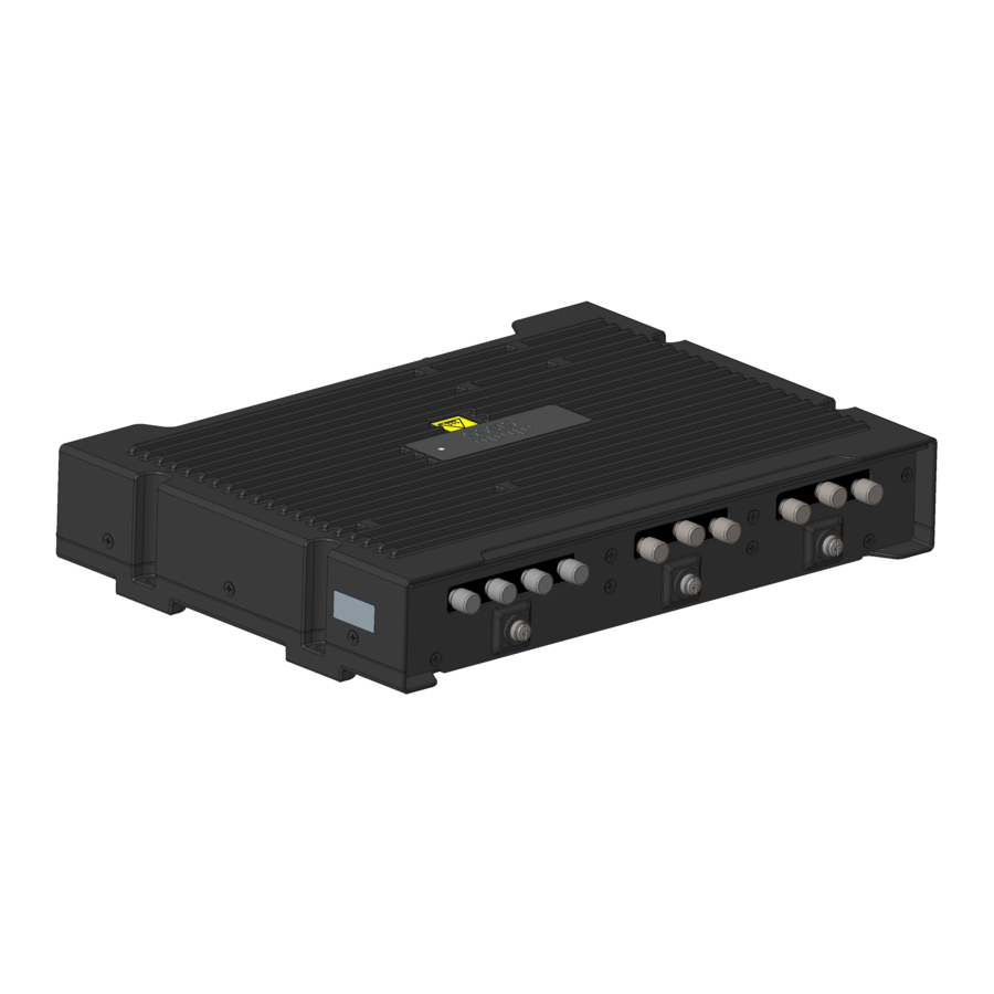
Figure 4: Cisco IR1835 Router Front Panel Overview This section describes the components of the IR1800 router. The IR1835 is used as an example since this SKU is the full featured router. Cisco Catalyst IR1800 Rugged Series Router Hardware Installation Guide... -
Page 22: Rear Panel Overview
This section describes the components of the IR1800 router. The IR1835 is used as an example since this SKU is the full featured router. Item Description Wi-Fi Interface Module (WIM) 0/3/0 Cisco Catalyst IR1800 Rugged Series Router Hardware Installation Guide... -
Page 23: Pluggable Modules
Table 3: Supported Gigabit Ethernet SFPs Gigabit Ethernet Distance Fiber Commercial Extended Industrial Digital Optical Monitoring 0C to +70C -5C to -40C to +85C +85C GLC-SX-MM-RGD 220-550 m — — — Cisco Catalyst IR1800 Rugged Series Router Hardware Installation Guide... - Page 24 80 km Duplex — — DWDM-SFP-3112 80 km Duplex — — GLC-BX-D-I 10 km Single — — Strand GLC-BX-U-I 10 km Single — — Strand GLC-TE 100 km Copper — — Cisco Catalyst IR1800 Rugged Series Router Hardware Installation Guide...
-
Page 25: Wireless Interface Module (Wim)
Product Overview Wireless Interface Module (WIM) For the most up-to-date list of supported SFP models for Cisco Industrial Devices, see the Cisco Optics-to-Device Compatibility Matrix. Wireless Interface Module (WIM) The Wireless Interface Module (WIM) Complete details on the WIM are found in this chapter:... - Page 26 Either the SFP or the RJ45 LED will Flashing Green: Link with activity. Note be On, depending on what type of Off: No link, or port is off. interface is used in the combo port. Cisco Catalyst IR1800 Rugged Series Router Hardware Installation Guide...
-
Page 27: Reset Button
Antenna Selection and Installation, on page 37 lists the supported antennas and accessories for the IR1800 with a wireless pluggable module. For detailed information about Cisco antennas for industrial routers, see the Cisco Industrial Routers and Industrial Wireless Access Points Antenna Guide. - Page 28 Module offers 5G capability to the IoT Module, on page 49 chapter. Industrial Router family. The product ID for the pluggable module is P-5GS6-GL. The P-5GS6-GL uses the FN980 Telit modem. Cisco Catalyst IR1800 Rugged Series Router Hardware Installation Guide...
-
Page 29: Power Supply
The IR1800 obtains GPS service through either the installed PIM modules, or from the dedicated IRM-GNSS-ADR module. Cisco supports GPS only with the initial IOS XE release 17.7.1. Please inquire with your sales representative for a roadmap of support for additional constellations. -
Page 30: Usb Ports
• A connection to the USB port can only be made in a nonhazardous environment. • The USB port cover must be reinstalled before the router can be deployed in a hazardous environment. Cisco Catalyst IR1800 Rugged Series Router Hardware Installation Guide... -
Page 31: Installing The Router
Only trained and qualified personnel should be allowed to install, replace, or service this equipment. Statement 1030 Warning Ultimate disposal of this product should be handled according to all national laws and regulations. Statement 1040 Cisco Catalyst IR1800 Rugged Series Router Hardware Installation Guide... -
Page 32: Equipment, Tools, And Connections
No antennas are shipped with the IR1800 Series router. Items Shipped with Your Router Unpack the box and verify that all the items listed in the invoice are shipped with the Cisco IR1800. The following items are shipped with your router: •... -
Page 33: Installing The Router
1/4 in. (6 to 7 mm). Mounting on a Wall, Table, or Other Flat Surface The Cisco IR1800 can be mounted in a vertical or horizontal orientation. It can be mounted using screws into studs in the wall, or using anchor mounting for hollow walls. - Page 34 Figure 6: Mounting Hole Dimensions Note Mount the router in a proper wall structure to carry the weight of the device. Whenever possible, use a mounting location where the screws will go into wall studs. Cisco Catalyst IR1800 Rugged Series Router Hardware Installation Guide...
-
Page 35: Installing A Din Rail
Use appropriate wall anchor mounts. Installing a DIN Rail The DIN rail kit must be ordered separately. The Cisco part number is IR1800-DINRAIL. Note The DIN rail brackets come assembled in horizontal orientation. If your installation requires vertical orientation, disassemble the components and reassemble them. -
Page 36: Mounting The Din Rail Bracket On The Router (Horizontal)
After the bracket is attached to the router, it can be mounted onto the DIN rail. Attaching the Bracket to the DIN Rail To attach the Cisco IR1800 with the bracket to a DIN rail, see the following image and follow the steps provided. - Page 37 Release the plastic latches after the DIN rail is firmly within the clamps to secure it. The router is now installed in the DIN rail. Step 4 To remove the router from the DIN rail, reverse the procedure. Cisco Catalyst IR1800 Rugged Series Router Hardware Installation Guide...
-
Page 38: Changing The Bracket Orientation
Horizontal orientation is shown in the following figure: Figure 8: Horizontal Orientation A vertical orientation is shown in the following figure: Cisco Catalyst IR1800 Rugged Series Router Hardware Installation Guide... -
Page 39: Bracket Disassembly
Installing the Router Bracket Disassembly Figure 9: Vertical Orientation Bracket Disassembly To disassemble the bracket hardware, see the following figure and follow the steps provided. Cisco Catalyst IR1800 Rugged Series Router Hardware Installation Guide... - Page 40 Slide the DIN rail clamps (2) away from the plastic latches (4) and remove them. Step 3 Slide the plastic latches (4) off the DIN rail plate, and remove the two springs (3). Cisco Catalyst IR1800 Rugged Series Router Hardware Installation Guide...
-
Page 41: Bracket Reassembly
See the following figure and follow the steps provided. Screws DIN rail clamps Springs Plastic latches DIN rail clips Procedure Step 1 Slide the two springs (3) onto the thin tabs. Cisco Catalyst IR1800 Rugged Series Router Hardware Installation Guide... -
Page 42: Mounting The Din Rail Bracket On The Router (Vertical)
Reattach the two DIN rail clips (5) to the mounting bracket in a vertical orientation using 9 in-lbs of torque. Mounting the DIN Rail Bracket on the Router (Vertical) Procedure Step 1 Attach the DIN rail bracket to the back of the router, as shown in the following figure. Cisco Catalyst IR1800 Rugged Series Router Hardware Installation Guide... -
Page 43: Installing The Router Ground Connection
Note Cable distribution system should be grounded (earthed) in accordance with ANSI/NFPA 70, the National Electrical Code (NEC), in particular Section 820.93, Grounding of Outer Conductive Shield of a Coaxial Cable. Cisco Catalyst IR1800 Rugged Series Router Hardware Installation Guide... - Page 44 What to do next After you install and properly ground the router, you can connect the power wiring, the LAN cables, and the cables for administrative access, as required for your installation. Cisco Catalyst IR1800 Rugged Series Router Hardware Installation Guide...
-
Page 45: Antenna Selection And Installation
Introduction to Selecting Antennas Note Before you install the Cisco IR1800 router on a table, wall, or DIN rail, install the antennas on the pluggable module. It is difficult to install the antennas after the router is installed. This chapter contains information about selecting antennas for the IR1800 router. - Page 46 Install the IR1800, pluggable modules, and antennas above floor level in office environments, or near the ceiling, for better performance because most obstructions tend to be near the floor level. Cisco Catalyst IR1800 Rugged Series Router Hardware Installation Guide...
-
Page 47: Supported Antennas For The Ir1800 Series Router
LTE. For details of which bands each antenna supports, please consult the detailed information for each antenna. Cisco Catalyst IR1800 Rugged Series Router Hardware Installation Guide... -
Page 48: Pluggable Interface Modules
4x single-band Wi-Fi (2x 2.4 GHz and 2x 5 GHz) W-ANTM2050D-RPSMA Indoor Antennas Antenna Antenna Specifications Indoor LTE LTE-ANTM2-SMA-D Antenna Type: Dipole Frequency Band: 617-960 MHz 1400-1700 MHz 1710-2690 MHz 3400-3900 MHz 5150-6000 MHz Connector: SMA (m) Cisco Catalyst IR1800 Rugged Series Router Hardware Installation Guide... -
Page 49: Outdoor Antennas
698-960 MHz 1695-2690 MHz 3400-3800 MHz Connector: N-type (f) Mast-Mounted Outdoor ANT-5G-OMNI-OUT-N Antenna Type: Dipole 5G, FR1 Frequency Band: 617-960 MHz 1448-1511 MHz 1695-2690 MHz 3300-4200 MHz 5150-7125 MHz Connector: N-type (f) Cisco Catalyst IR1800 Rugged Series Router Hardware Installation Guide... -
Page 50: Outdoor And Transportation Antennas
Supported Extension Bases and Cables Antenna Type Antenna PID Cable PID Extension Base Indoor (cellular) LTE-ANTM2-SMA-D CAB-L240-10-SM-TM LTE-AE-MAG-SMA CAB-L240-15-SM-TM CAB-L240-20-SM-TM Indoor (Wi-Fi) W-ANTM2050D-RPSMA= — — Outdoor ANT-4G-OMNI-OUT-N CAB-L240-10-SM-NM — (cellular) ANT-5G-OMNI-OUT-N Cisco Catalyst IR1800 Rugged Series Router Hardware Installation Guide... -
Page 51: Pluggable Interface Modules
• Installing a PIM, on page 44 Introduction to Installing Pluggable Interface Modules This section describes the equipment and the procedures for successfully installing the Cisco Pluggable Interface Modules (PIM). The highlights of the LTE PIM are: • All cellular interfaces are supported through a PIM •... -
Page 52: Installing A Pim
Remove the screw (1) holding the access plate which covers the SIM slots. The access plate is located on the side of the module, as shown in the following figures. Cisco Catalyst IR1800 Rugged Series Router Hardware Installation Guide... - Page 53 Access plate screw Step 4 Install your SIMs as shown in the following figure. Make note of the slot number and SIM orientation. Figure 14: SIM Installation Micro SIMs SIM 0 Cisco Catalyst IR1800 Rugged Series Router Hardware Installation Guide...
- Page 54 USB port Step 7 Tighten the latch lock screw to a torque of 2.8 to 3.8 inch-lbs (0.3 to 0.4 Newton meter). The following figure shows a finished USB cover installation. Cisco Catalyst IR1800 Rugged Series Router Hardware Installation Guide...
- Page 55 Attach your antenna cables to the ports on the pluggable module. There are different instructions for each antenna type. So be sure to consult the corresponding antenna documentation for proper orientation and torque to install them. Cisco Catalyst IR1800 Rugged Series Router Hardware Installation Guide...
- Page 56 Pluggable Interface Modules Installing a PIM If no antenna cables are being installed on a port, make sure the caps are installed on the unused Note connector. Cisco Catalyst IR1800 Rugged Series Router Hardware Installation Guide...
-
Page 57: Sub-6 Ghz Pluggable Interface Module
• On the IR1101, when plugged into the base, the module is accessible via Cellular 0/1/0, 0/1/1. • On the IR1101, the module is not supported on the expansion module. • On the IR1800, the cellular modems are accessible via Cellular 0/4/0, 0/4/1, 0/5/0, 0/5/1. Cisco Catalyst IR1800 Rugged Series Router Hardware Installation Guide... -
Page 58: Pluggable Interface Module Overview
Figure 18: 5G Pluggable Interface Module - P-5GS6-GL Antenna 1 (SMA) GPS (SMA) Antenna 3 (SMA) Antenna 0 (SMA) Antenna 2 (SMA) Enable LED SIM 0 LED SIM 1 LED GPS LED M3.5 thumb-screw Service LED Cisco Catalyst IR1800 Rugged Series Router Hardware Installation Guide... -
Page 59: Led Behaviors
• Off: GPS not configured • Yellow: Software defined • Green: GPS configured • Green Flash: GPS acquiring (flashing done by SW) Service Green, Yellow, Blue Service Indication LED • Yellow: 3G Cisco Catalyst IR1800 Rugged Series Router Hardware Installation Guide... -
Page 60: Rf Band And Port Mapping For The P-5Gs6-Gl Antenna
B39, B40, B41, B42, B43, B46, B48, B66 5G NR FR1 n1, n2, n3, n7, n25, n41, n66, n1, n2, n3, n7, n25, n38, n40, n41, n48, n66, n77, n77, n78, n79 n78, n79 Cisco Catalyst IR1800 Rugged Series Router Hardware Installation Guide... -
Page 61: Thermal Mitigation
This applies to both the 4G LTE and 5G NR FR1 operation of the P-5GS6-GL. Table 9: Thermal Mitigation Levels Level Description Level 0 Normal mode, no thermal throttling. Level 1 Uplink throttling, via reduced UL TX duty cycle. Cisco Catalyst IR1800 Rugged Series Router Hardware Installation Guide... - Page 62 “no service” for the P-5GS6-GL . Thermal Shutdown This occurs after Level 3. Note Cisco does not recommend operation deep into level 2 as this may affect communication range via MTPL backoff. Table 10: Thermal Mitigation Table - IR1101 Hardware...
-
Page 63: Attaching An Antenna
Normal, Level 0 70°/158° Throttled, Level 1 70°/158° Normal, Level 0 75°/167° Throttled, Level 1 Attaching an Antenna To attach the antenna in the Pluggable Interface Module, perform the below steps: Cisco Catalyst IR1800 Rugged Series Router Hardware Installation Guide... - Page 64 1. Attach each SMA cable to the ports as indicated in the table mappings. 2. Ensure that you tighten and secure each SMA cable into the SMA connector on the PIM. Cisco Catalyst IR1800 Rugged Series Router Hardware Installation Guide...
-
Page 65: Cisco Wi-Fi Interface Module (Wim)
This overview describes the Cisco Wide Pluggable Form Factor WIFI6 AP Module for Industrial Routers. The PID is WP-WIFI6-x. The Cisco Wi-Fi Interface Module will be refered to as the WIM from this point forward. Highlights of the WIM are: •... - Page 66 Power is on, module is not yet functional Green Module is fully functional Table 13: Wi-Fi LED LED Status Status Type Description Solid Green Association Status Normal operating condition, but no wireless client associated. Cisco Catalyst IR1800 Rugged Series Router Hardware Installation Guide...
-
Page 67: Installation
Installation The Cisco Wi-Fi Interface Module remove and replace options are shown in the following steps. The Router may have a blank plate covering the Wi-Fi Interface Module slot. This will need to be removed prior to installing the Wi-Fi Interface Module. The following example shows the Wi-Fi Interface Module. - Page 68 (2) on the face of the device. Push the Wi-Fi Module all the way into the device until you feel it seat, and then torque the latch lock screw 8-10 inch-pound (0.9 to 1.1 newton meter). Cisco Catalyst IR1800 Rugged Series Router Hardware Installation Guide...
-
Page 69: Transmit Power And Receive Sensitivity
5 GHz Radio 2.4 GHz Radio Spatial Streams Number of Active Total TX power RX sensitivity Total TX power RX sensitivity Antennas (dBm) (dBm) (dBm) (dBm) 6 Mbps 24 Mbps 54 Mbps Cisco Catalyst IR1800 Rugged Series Router Hardware Installation Guide... - Page 70 Spatial Streams Number of Active Total TX power RX sensitivity Total TX power RX sensitivity Antennas (dBm) (dBm) (dBm) (dBm) MCS0 — — MCS9 — — MCS0 — — MCS9 — — Cisco Catalyst IR1800 Rugged Series Router Hardware Installation Guide...
- Page 71 Table 23: 802.11ax HE80 5 GHz Radio 2.4 GHz Radio Spatial Streams Number of Active Total TX power RX sensitivity Total TX power RX sensitivity Antennas (dBm) (dBm) (dBm) (dBm) MCS0 — — Cisco Catalyst IR1800 Rugged Series Router Hardware Installation Guide...
-
Page 72: Thermal Mitigation
2.4 and 5 GHz radios may throttle to 1x1 SISO. In 1x1 SISO mode only antenna port A is active, and each radio is restricted to single spatial stream data rates. Cisco Catalyst IR1800 Rugged Series Router Hardware Installation Guide... -
Page 73: Ssd Module
The highlights of the SSD module are: • Provides an additional 100 GB of additional Flash memory storage. • Provides space to store application data for Cisco IOx. • The SSD is a Field Replaceable Unit, but is not hot-swappable. -
Page 74: Installing An Ssd Module
Step 2 Insert the SSD module into the slot in the panel such that the previously removed screws (1) align with the screw holes (2), as shown in the following figure. Cisco Catalyst IR1800 Rugged Series Router Hardware Installation Guide... - Page 75 After the module is properly inserted, tighten the module plate to the panel with the two screws. The screws should be torqued to 2-3 in-lb (0.2-0.3 Newton meter). Step 4 The installation is now complete. Cisco Catalyst IR1800 Rugged Series Router Hardware Installation Guide...
- Page 76 SSD Module Installing an SSD Module Cisco Catalyst IR1800 Rugged Series Router Hardware Installation Guide...
-
Page 77: Gps Field Replaceable Unit Module
LTE module, for more accurate dead reckoning performance. The part number is IRM-GNSS-ADR. The following figure shows a GPS FRU module. Figure 26: GPS FRU Module Cisco Catalyst IR1800 Rugged Series Router Hardware Installation Guide... -
Page 78: Installation And Removal Of A Gps Fru Module
GPS Field Replaceable Unit Module Installation and Removal of a GPS FRU Module The IRM-GNSS-ADR hardware is capable of supporting various GNSS constellations. Cisco supports GPS only on this module with IOS XE release 17.7.1. Please inquire with your sales representative for a roadmap of support of additional constellations on the IRM-GNSS-ADR module. - Page 79 Step 4 The installation is now complete. Step 5 To remove the module, reverse the steps: a. Power off the device. b. Remove the screws. c. Pull out the module. Cisco Catalyst IR1800 Rugged Series Router Hardware Installation Guide...
- Page 80 GPS Field Replaceable Unit Module Installation and Removal of a GPS FRU Module Cisco Catalyst IR1800 Rugged Series Router Hardware Installation Guide...
-
Page 81: Digital I/O, Ignition, And Can Bus Connectivity
• Digital input and output can coexist on different channels. • LED Indicator: Provisionable; On: Active, Off: Non-active. • 4kV surge protected (IEC 61000-4-5). The Digital I/O Connector The following figure shows the connector. Cisco Catalyst IR1800 Rugged Series Router Hardware Installation Guide... - Page 82 For vehicle installations, it is required to connect the ignition input, and use the Ignition Power Management feature of the router. This eliminates unnecessary power cycling of the router whenever the vehicle is turned off and then turned back on. Cisco Catalyst IR1800 Rugged Series Router Hardware Installation Guide...
-
Page 83: Digital I/O Specifications
• High-speed CAN Bus 2.0B: ISO 11898-1 data link layer, ISO 11898-2 and ISO-11898-5 physical layer up to 1 Mbs data rate (software dependent) • Maximum cable length between 500 m (125 kbit/s) and 40 m (1 Mbit/s) • 120-ohms CAN Bus termination Cisco Catalyst IR1800 Rugged Series Router Hardware Installation Guide... -
Page 84: Can Bus Power Connector
• The OBDII port is always powered up, even when the vehicle is turned off • When connecting an IR1800 CAN Bus, the vehicles owner must review the characteristics of the ODB2 power and fuse protection Cisco Catalyst IR1800 Rugged Series Router Hardware Installation Guide... - Page 85 The list of cables is illustrated in the following figure. The box labeled Vehicle Conn is the connector that is connected to a car or truck. The box labeled Tool Conn is for attaching diagnostic tool. The box labeled MiniFit-Jr is the connector that connects to the IR1800. Cisco Catalyst IR1800 Rugged Series Router Hardware Installation Guide...
- Page 86 Digital I/O, Ignition, and CAN Bus Connectivity On-Board Diagnostic (OBD-II) Cisco Catalyst IR1800 Rugged Series Router Hardware Installation Guide...
-
Page 87: Connecting The Router
If you connect or disconnect the console cable with power applied to the switch or any device on the network, an electrical arc can occur. This could cause an explosion in hazardous location installations. Be sure that power is removed or the area is nonhazardous before proceeding. Statement 1080 Cisco Catalyst IR1800 Rugged Series Router Hardware Installation Guide... -
Page 88: Connecting A Pc, Server, Or Workstation
If your laptop or PC warns you that you do not have the proper drivers to communicate with the router, you can obtain them from your computer manufacturer or from this location: https://www.silabs.com/developers/usb-to-uart-bridge-vcp-drivers Cisco Catalyst IR1800 Rugged Series Router Hardware Installation Guide... -
Page 89: Connecting To Dc Power And Can Bus Wiring
The IR1800 uses a DC power accessory kit (part number PWR-MF4-125W-AC). This needs to be ordered separately. The power entry receptacle is on the IR1800. The pinouts are shown in the following figure. Cisco Catalyst IR1800 Rugged Series Router Hardware Installation Guide... -
Page 90: Verifying Connections
(CAB-PWR-15-MF4). The following is a diagram of the cable: Verifying Connections To verify that all the devices are properly connected to the router, turn on all the connected devices, and then check the LEDs. Cisco Catalyst IR1800 Rugged Series Router Hardware Installation Guide... -
Page 91: Installing The Ip54 Kit
The intent of the IP54 kit is to provide supplementary protection to the router against dust and occasional splashing water. Cisco cannot guarantee prolonged reliable operation of the router if these guidelines are violated. - Page 92 • Screws to build the kit and attach it to IR1800 The front cover is shipped disassembled because it must be assembled onto the IR1800. The front cover comprises four parts. Figure 32: Front Cover Parts Top Cover Plate Cisco Catalyst IR1800 Rugged Series Router Hardware Installation Guide...
-
Page 93: Installing The Ip54 Kit
The front cover of the IP54 kit is installed around the IR1800 using the four parts previously listed and the screws provided. Before you begin Make sure all cables are removed and that the desired FRUs or blanks are installed before assembling the front IP54 cover. Cisco Catalyst IR1800 Rugged Series Router Hardware Installation Guide... - Page 94 Step 5 Attach the top cover to the bottom cover using four of the provided screws. Note All the cables should be wedged between the top and bottom foam pieces. Cisco Catalyst IR1800 Rugged Series Router Hardware Installation Guide...
- Page 95 IP54 back cover, it will interfere with the installation. Step 2 Attach the back cover to the back of the chassis over the pluggable modules using eight of the provided screws. Cisco Catalyst IR1800 Rugged Series Router Hardware Installation Guide...
- Page 96 Tighten the screws to a torque of 5 to 6 in-lbs. Step 4 After the cover is in place, the antenna cables can be attached to the pluggable modules, as needed. The following figure shows the final assembly. Cisco Catalyst IR1800 Rugged Series Router Hardware Installation Guide...
-
Page 97: Technical Specifications
This chapter provides specifications for the IR1800. Complete specifications for the IR1800 can be found in the marketing data sheet. Router Specifications The following table lists the specifications of the Cisco IR1800. Description Design Specification Dimensions 11.00”W x 7.16” x 2.02”... - Page 98 Storage Temperature and Altitude Temperature: -40 to +85 degrees C Altitude: up to 15,000 feet Input Voltage Nominal voltage: 12V/24V (+/-20%) Min/Max voltage: +9.6V to +36V DC input Typical Current 5.5A Typical/Maximum Power Consumption Cisco Catalyst IR1800 Rugged Series Router Hardware Installation Guide...
-
Page 99: Regulatory Compliance
Changing Output Power, on page 104 • Obtaining Documents from Cisco.com, on page 104 Related Documentation The following are the various locations containing important information: • Cisco.com: www.cisco.com • Warranty Information: www.cisco-warrantyfinder.com Cisco Catalyst IR1800 Rugged Series Router Hardware Installation Guide... -
Page 100: Installation Warning And Caution Statements
Regulatory Compliance Installation Warning and Caution Statements • Cisco Information Packet, consisting of Cisco Limited Warranty, Disclaimer of Warranty, End User License Agreement, and United States Federal Communications Commission Notice: www.cisco.com/en/US/docs/general/warranty/English/SL3DEN.html • Cisco Marketplace: www.cisco.com/pcgi-bin/marketplace/welcome.pl • Cisco Product Documentation: www.cisco.com/go/techdocs •... -
Page 101: Hazardous Locations Standards And Marking Strings
• Class 1, Div 2, Groups A B C D • Class I, Zone 2, AEx ec IIC T4 Gc • UL 21 ATEX 2512X • Ex ec IIC T4 Gc Cisco Catalyst IR1800 Rugged Series Router Hardware Installation Guide... -
Page 102: Emc Information
Class A Notice for FCC Modifying the equipment without Cisco’s authorization may result in the equipment no longer complying with FCC requirements for Class A digital devices. In such an event, your right to use the equipment may be limited by FCC regulations, and you may be required to correct any interference to radio or television communications at your own expense. -
Page 103: European Community, Switzerland, Norway, Iceland, And Liechtenstein
® Cisco Catalyst IR1800 Rugged Series Router are certified to the requirements of RSS-247. The use of this device in a system operating either partially or completely outdoors may require the user to obtain a license for the system according to the Canadian regulations. For further information, contact your local Industry Canada office. -
Page 104: Declaration Of Conformity For Rf Exposure
Note This equipment is intended to be used in all EU and EFTA countries. Outdoor use may be restricted to certain frequencies or may require a license for operation or both. For more details, contact the Cisco Corporate Compliance team. -
Page 105: This Device Meets Fcc Guidelines For Exposure To Radio Waves
L’émetteur/récepteur exempt de licence contenu dans le présent appareil est conforme aux CNR d’Innovation, Sciences et Développement économique Canada applicables aux appareils radio exempts de licence. L’exploitation est autorisée aux deux conditions suivantes : Cisco Catalyst IR1800 Rugged Series Router Hardware Installation Guide... -
Page 106: This Device Meets The Industry Canada Guidelines For Exposure To Radio Waves
CAN ICES-3 (A)/NMB-3(A) The Country Code Selection feature is disabled for products marketed in the US/Canada. Additional Information on RF Exposure You can find additional information on RF exposure in the following links: Cisco Catalyst IR1800 Rugged Series Router Hardware Installation Guide... -
Page 107: Emc Class A Notices And Warnings
Cisco Systems for use within the EU or countries that have implemented the EU directives. The use of software or firmware not supported or provided by Cisco Systems may result in the equipment not being compliant with the regulatory requirements. - Page 108 Urządzenie jest zgodne z ogólnymi wymaganiami oraz szczególnymi warunkami określonymi Dyrektywą UE: 2014/53/UE. Português [Portuguese]: Este equipamento está em conformidade com os requisitos essenciais e outras provisões relevantes da Directiva 2014/53/UE. Cisco Catalyst IR1800 Rugged Series Router Hardware Installation Guide...
-
Page 109: National Restrictions
Questo prodotto è conforme alla specifiche di Interfaccia Radio Nazionali e rispetta il Piano Nazionale di ripartizione delle frequenze in Italia. Se non viene installato all’interno del proprio fondo, l’utilizzo di prodotti Wireless LAN richiede una “Autorizzazione Generale”. Consultare http://www.mise.gov.it/index.php/it/comunicazioni Cisco Catalyst IR1800 Rugged Series Router Hardware Installation Guide... -
Page 110: Latvia
This is a Class A product based on the standard of the VCCI Council. If this equipment is used in a domestic environment, radio interference may occur, in which case, you may be required to take corrective actions. ステートメント 191 日本向け VCCI クラス A に関する警 告 警告 この装置は、クラスA機器です。この装置を住宅環境で使用すると電波妨害を引き 起こすことが あります。この場合には使用者が適切な対策を講ずるよう要求される ことがあります。 VCCI-A Cisco Catalyst IR1800 Rugged Series Router Hardware Installation Guide... -
Page 111: Statement 1008-Class 1 Laser Product
Pluggable optical modules comply with IEC 60825-1 Ed. 3 and 21 CFR 1040.10 and 1040.11 with or without exception for conformance with IEC 60825-1 Ed. 3 as described in Laser Notice No. 56, dated May 8, 2019. Cisco Catalyst IR1800 Rugged Series Router Hardware Installation Guide... -
Page 112: 聲明4011-國家通信委員會警告
• For Cisco IR1800 Series products, go here. Note If you still have questions regarding the compliance of these products, or you cannot find the information you are looking for, send an email to Cisco at complianceinfo@cisco.com. Cisco Catalyst IR1800 Rugged Series Router Hardware Installation Guide...