Table of Contents
Advertisement
Quick Links
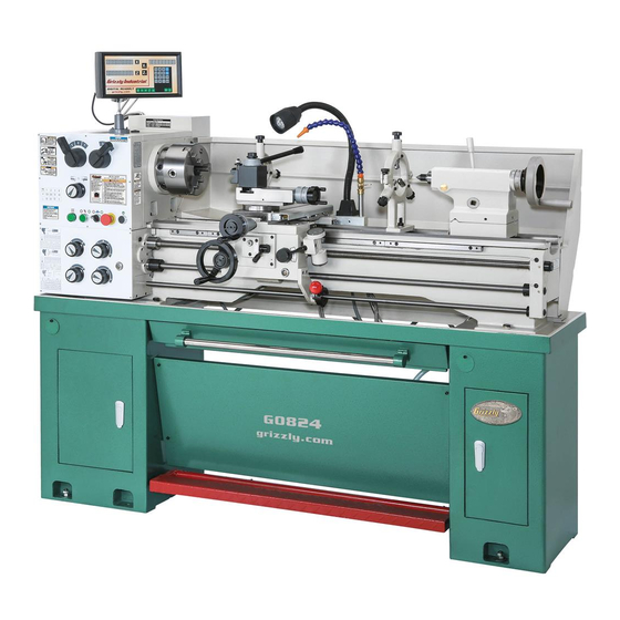
MODEL G0824
14" X 40" GUNSMITH LATHE
OWNER'S MANUAL
(For models manufactured since 12/16)
COPYRIGHT © MARCH, 2017 BY GRIZZLY INDUSTRIAL, INC. REVISED JUNE, 2018 (HE)
WARNING: NO PORTION OF THIS MANUAL MAY BE REPRODUCED IN ANY SHAPE
OR FORM WITHOUT THE WRITTEN APPROVAL OF GRIZZLY INDUSTRIAL, INC.
#BLJHKB18736 PRINTED IN CHINA
V1.06.18
Advertisement
Table of Contents

Related Manuals for Grizzly G0824


Summary of Contents for Grizzly G0824
- Page 1 OWNER'S MANUAL (For models manufactured since 12/16) COPYRIGHT © MARCH, 2017 BY GRIZZLY INDUSTRIAL, INC. REVISED JUNE, 2018 (HE) WARNING: NO PORTION OF THIS MANUAL MAY BE REPRODUCED IN ANY SHAPE OR FORM WITHOUT THE WRITTEN APPROVAL OF GRIZZLY INDUSTRIAL, INC.
- Page 2 This manual provides critical safety instructions on the proper setup, operation, maintenance, and service of this machine/tool. Save this document, refer to it often, and use it to instruct other operators. Failure to read, understand and follow the instructions in this manual may result in fire or serious personal injury—including amputation, electrocution, or death.
-
Page 3: Table Of Contents
Table of Contents INTRODUCTION ..........2 Threading ............. 54 Contact Info............ 2 Coolant System..........58 Manual Accuracy ........... 2 SECTION 5: ACCESSORIES ......59 Identification ........... 3 Controls & Components ......... 4 SECTION 6: MAINTENANCE ......63 Machine Data Sheet ........7 Schedule ............ -
Page 4: Introduction
ID label (see below). This information is required for us to provide proper tech support, and it helps us determine if updated documenta- tion is available for your machine. Manufacture Date Serial Number Model G0824 (Mfd. Since 12/16) -
Page 5: Identification
Compound Rest U. Storage Cabinet Cross Slide V. Quick-Change Gearbox Controls (see Page K. Coolant Valve 4 for details) Steady Rest To reduce your risk of serious injury, read this entire manual BEFORE using machine. Model G0824 (Mfd. Since 12/16) -
Page 6: Controls & Components
E. Quick-Change Gearbox Dials: Control the leadscrew and feed rod speed for threading and feeding operations. Thread Dial Chart: Indicates where on the thread dial to engage the half nut when cut- ting inch threads. Model G0824 (Mfd. Since 12/16) - Page 7 Cross Slide Handwheel: Moves the cross slide toward and away from the workpiece. ⁄ " Square-Drive Lock-Down: Used with a Dial is graduated in increments of 0.002" torque wrench for precise alignment of centers. (0.200" per full revolution). Model G0824 (Mfd. Since 12/16)
- Page 8 Figure 6. End gear components. Configuring the end gears (shown in Figure 6) controls the speed of the leadscrew for threading, or the feed rod for power feed operations. Foot Brake Figure 7. Foot brake and spindle lever. Model G0824 (Mfd. Since 12/16)
-
Page 9: Machine Data Sheet
Machine Data Sheet MACHINE DATA SHEET Customer Service #: (570) 546-9663 · To Order Call: (800) 523-4777 · Fax #: (800) 438-5901 MODEL G0824 14" X 40" GUNSMITH LATHE WITH 2" SPINDLE BORE Product Dimensions: Weight................................1300 lbs. Width (side-to-side) x Depth (front-to-back) x Height..............78 x 31 x 61-1/2 in. - Page 10 The information contained herein is deemed accurate as of 5/5/2019 and represents our most recent product specifications. Model G0824 PAGE 2 OF 3 Due to our ongoing improvement efforts, this information may not accurately describe items previously purchased. Model G0824 (Mfd. Since 12/16)
- Page 11 Fluid Capacities Headstock Capacity..........................3.5 qt. Headstock Fluid Type............. ISO 32 (e.g. Grizzly T23963, Mobile DTE Light) Gearbox Capacity............................. 24 oz. Gearbox Fluid Type..............ISO 68 (e.g. Grizzly T23962, Mobile Vactra 2) Apron Capacity............................7 oz. Apron Fluid Type............... ISO 68 (e.g. Grizzly T23962, Mobile Vactra 2) Coolant Capacity............................
-
Page 12: Section 1: Safety
Never operate under the influence of drugs or injury or blindness from flying particles. Everyday alcohol, when tired, or when distracted. eyeglasses are NOT approved safety glasses. -10- Model G0824 (Mfd. Since 12/16) - Page 13 Make sure they are properly installed, you experience difficulties performing the intend- undamaged, and working correctly BEFORE ed operation, stop using the machine! Contact our operating machine. Technical Support at (570) 546-9663. -11- Model G0824 (Mfd. Since 12/16)
-
Page 14: Additional Safety For Metal Lathes
CLEARING CHIPS. Metal chips can be razor MEASURING WORKPIECE. To reduce risk of sharp. Avoid clearing them by hand or with a rag. Use a brush or vacuum instead. entanglement, never measure rotating workpieces. -12- Model G0824 (Mfd. Since 12/16) -
Page 15: Additional Chuck Safety
Always disconnect the lathe from power additional training from an experienced chuck user before performing these procedures. before using a chuck. -13- Model G0824 (Mfd. Since 12/16) -
Page 16: Section 2: Power Supply
To reduce the risk of these hazards, avoid over- loading the machine during operation and make sure it is connected to a power supply circuit that meets the specified circuit requirements. -14- Model G0824 (Mfd. Since 12/16) - Page 17 -15- Model G0824 (Mfd. Since 12/16)
-
Page 18: Section 3: Setup
IMPORTANT: Save all packaging materials until you are completely satisfied with the machine and have resolved any issues between Grizzly or the shipping agent. You MUST have the original pack- aging to file a freight claim. It is also extremely helpful if you need to return your machine later. -
Page 19: Inventory
Z. Dead Center MT#3 Carbide Tip ....1 AA. Dead Center MT#3 HSS Tip ...... 1 AB. Handwheel Handles ........2 AC. Tool Holder (One Installed) ......2 AD. End Gear 120/127T (Installed) ....1 Figure 11. Toolbox inventory. -17- Model G0824 (Mfd. Since 12/16) -
Page 20: Cleanup
Figure 12. T23692 Orange Power Degreaser. Repeat Steps 2–3 as necessary until clean, then coat all unpainted surfaces with a quality metal protectant to prevent rust. -18- Model G0824 (Mfd. Since 12/16) -
Page 21: Site Considerations
Wall 96" 30" Minimum Electrical Box Access Cover Lathe Keep Workpiece 32" Loading Area Unobstructed 24" Minimum Figure 13. Minimum working clearances. -19- Model G0824 (Mfd. Since 12/16) -
Page 22: Assembly
(if applicable). With the exception of the handwheels and DRO unit, the Model G0824 is shipped fully assembled. To assemble lathe: Thread handles into handwheels, as shown in Figure 14. -
Page 23: Lifting & Placing
(see Page 4 for reference). 10. Lower lathe into position. Remove back splash so it does not get dam- 11. Re-install back splash. aged when lathe is raised. -21- Model G0824 (Mfd. Since 12/16) -
Page 24: Anchoring To Floor
Sold individually. Stud size: M12-1.75 x 72. Front Mounting Holes Rear Mounting Figure 20. G7160 Machine Mount. Holes Figure 18. Locations for mounting lathe. -22- Model G0824 (Mfd. Since 12/16) -
Page 25: Leveling
Add the coolant of your choice now. For detailed instructions on where the coolant tank is located and how to add fluid, refer to Coolant System Service on Page 69. Figure 21. Model H2683 Master Machinist's Level. -23- Model G0824 (Mfd. Since 12/16) -
Page 26: Power Connection
Refer to Extension Cords on Page 15 for more terminals. information. Ground Wire Connected Hot Wires Connected Incoming Power Cord Figure 23. Incoming ground and hot wires connected. -24- Model G0824 (Mfd. Since 12/16) -
Page 27: Test Run
Secure chuck and jaws, if installed (refer to Chuck Installation on Page 30). Note: If a chuck is not installed on the lathe, you do not need to install one for this test. -25- Model G0824 (Mfd. Since 12/16) - Page 28 Make sure spindle lever is in OFF (middle) position (see Figure 26) to prevent unex- pected startup when power is enabled. Note: You need to pull the lever out (or right) to disengage the lug in order to adjust the position. -26- Model G0824 (Mfd. Since 12/16)
-
Page 29: Spindle Break-In
Press Emergency Stop/RESET button and DISCONNECT MACHINE FROM POWER! Congratulations! The spindle break-in is com- plete. We recommend changing the headstock and gearbox oil before operating the machine further (refer to Lubrication on Page 64). -27- Model G0824 (Mfd. Since 12/16) -
Page 30: Section 4: Operations
Read books/magazines or get formal training before beginning any proj- ects. Regardless of the content in this sec- tion, Grizzly Industrial will not be held liable for accidents caused by lack of training. -28- Model G0824 (Mfd. Since 12/16) -
Page 31: Chuck & Faceplate Mounting
Note: It is normal for studs to have a small amount of play or looseness after installing and tightening the cap screws. -29- Model G0824 (Mfd. Since 12/16) -
Page 32: Chuck Safety & Support Devices
LARGE, VERY HEAVY CHUCKS Fabricated Steel Pre-Threaded Hole Lifting Hook for Lifting Eye Figure 29. Inserting camlock studs into spindle cam holes. Figure 28. Examples of common devices used during chuck installation and removal. -30- Model G0824 (Mfd. Since 12/16) - Page 33 Spindle & Chuck Camlock Registration Marks Spindle INCORRECT INCORRECT Stud Too High: Stud Too Low: Turn In Turn Out One-Turn One-Turn Figure 32. Registration mark locations. Figure 31. Correcting an improperly installed stud. -31- Model G0824 (Mfd. Since 12/16)
-
Page 34: Chuck Removal
60° and tap it Cylinder again. Make sure all marks on cams and spindle are properly aligned for removal. Poor Scroll CORRECT Gear Engagement INCORRECT Figure 34. Jaw selection and workpiece holding. -32- Model G0824 (Mfd. Since 12/16) -
Page 35: Chuck Jaw Reversal
Rotate Top With help from another person or a holding Jaw 180º device, position workpiece so it is centered in chuck. Figure 35. Reversing the chuck jaws. -33- Model G0824 (Mfd. Since 12/16) -
Page 36: Faceplate
To reduce this risk, use a minimum of THREE independent clamping devices to hold the workpiece onto the faceplate. Figure 37. Example of non-cylindrical workpiece correctly mounted on the 4-jaw chuck. -34- Model G0824 (Mfd. Since 12/16) -
Page 37: Tailstock
This is a matter of trial and error, and it requires the use of precision measuring tools. -35- Model G0824 (Mfd. Since 12/16) - Page 38 Tang relock tailstock. Start spindle rotation, unlock quill lock lever, then turn quill handwheel clockwise to feed tool into workpiece. Figure 41. Example photos of inserting tools with tangs into the tailstock. -36- Model G0824 (Mfd. Since 12/16)
- Page 39 Note: The marks on the offset indicator (see Figure 43) are arbitrary. For a precise offset, use a dial indicator to check quill movement while adjusting the screws. Tool Needed Hex Wrench 4mm ..........1 -37- Model G0824 (Mfd. Since 12/16)
- Page 40 Mount test or dial indicator so that plunger is on tailstock quill. Note: If necessary in the following step, refer to the Offsetting Tailstock subsection for detailed instructions. Figure 44. Turning a dead center. -38- Model G0824 (Mfd. Since 12/16)
-
Page 41: Centers
Using low amount of taper. spindle speeds will also reduce the heat and wear from friction. Figure 47. Adjust tailstock away from the operator. Repeat Steps 6–8 until desired accuracy is achieved. -39- Model G0824 (Mfd. Since 12/16) - Page 42 -40- Model G0824 (Mfd. Since 12/16)
- Page 43 Also, over-tightening will result in excessive friction and Drift Key Slot heat, which may damage the workpiece or center. Figure 51. Drift key slot in the side of the quill. -41- Model G0824 (Mfd. Since 12/16)
-
Page 44: Drill Chuck & Arbor
Refer to Mounting Figure 54 to secure it in place. Center in Tailstock and Removing Center from Tailstock. -42- Model G0824 (Mfd. Since 12/16) -
Page 45: Follow Rest
Lock the fingers with the set screws and jam nuts, then tighten the clamp knob. Tip: To reduce the effects of friction, lubricate the fingers with way oil during operation. -43- Model G0824 (Mfd. Since 12/16) -
Page 46: Carriage & Compound Locks
This will allow you to quickly return the compound rest to that exact angle the next time you need to cut threads. -44- Model G0824 (Mfd. Since 12/16) -
Page 47: Tool Post
DO NOT extend a cutting tool more than 2.5 be aligned to the spindle centerline (refer to times the width of its cross-section (e.g., Aligning Tailstock To Spindle Centerline 2.5 x 0.5" = 1.25"). on Page 38 for detailed instructions). -45- Model G0824 (Mfd. Since 12/16) -
Page 48: Spindle Spider
Merely tightening the spider screws against the Figure 61. Cutting tool aligned to the tailstock workpiece and leaving the jam nuts loose is not center. safe. Spiders screws that loosen during operation can crash into the lathe end cover. -46- Model G0824 (Mfd. Since 12/16) -
Page 49: Manual Feed
The compound rest has an indirect-read gradu- ated dial with 0.001" (0.02mm) increments. One full revolution of the handwheel moves the slide 0.100" (2.54mm). -47- Model G0824 (Mfd. Since 12/16) -
Page 50: Spindle Speed
Also, there are a large number of easy-to-use spindle speed calculators that can be found on the internet. These sources will help you take into account the applicable variables in order to deter- mine the best spindle speed for the operation. -48- Model G0824 (Mfd. Since 12/16) -
Page 51: Power Feed
If the feed selection lever and the half nut are engaged at the same time, machine damage could occur. Even though there is a lock-out device to prevent this, it could break if forced. -49- Model G0824 (Mfd. Since 12/16) - Page 52 (toward the tailstock), or the cross feed will travel toward the front of the lathe when the spindle is rotating clockwise (or toward the rear of the lathe). -50- Model G0824 (Mfd. Since 12/16)
- Page 53 0.0018 in./rev., as shown in Figure 71. The cross slide is now set up for a power feed rate of 0.0018 in./rev. 60T Gear 0.0018 in./rev. Figure 71. 0.0018 in./rev. location on feed chart. -51- Model G0824 (Mfd. Since 12/16)
-
Page 54: End Gears
"a " Position 127T Gear "a" row 127T Gear 120T Gear 60T Gear Bottom Position "b " "b" row Position Figure 76. Metric feed chart end gears. Figure 74. Power feed chart end gears. -52- Model G0824 (Mfd. Since 12/16) - Page 55 Figure 78. and cap screws removed earlier. "b" "a" Position Position Gear Gear (Flat Face (Stepped Out) Face Out) Support 120/127T Gears Screw Arm Support Support Hex Nut Figure 78. Arm support and end gears. -53- Model G0824 (Mfd. Since 12/16)
-
Page 56: Threading
14. Re-install end gear cover. 1 & V Dials A & C Dials 18 TPI Figure 81. 18 TPI and corresponding dial positions. Install 60T and 54T gears, as instructed in End-Gear Configuration Example on Page 53. -54- Model G0824 (Mfd. Since 12/16) - Page 57 Figure 82. Gearbox dial settings for 18 TPI. The lathe is now set up to cut 18 TPI threads. Disengaged Cross Slide Disengaged Carriage Halfnut Lever Feed Selection Engaged Lever Figure 83. Apron threading controls. -55- Model G0824 (Mfd. Since 12/16)
- Page 58 Important: You can engage on the number 1 on the thread dial to cut any thread if you do not want to use the chart, or if you forget any of the rules on the next page. -56- Model G0824 (Mfd. Since 12/16)
- Page 59 Odd TPI: For threading odd numbered TPI, use any numbered line on the thread dial (see the example in Figure 88). Table Thread Dial T.P.I. SCALE 1, 3, 5, 7 Figure 88. Any number on dial for threading odd numbered TPI. -57- Model G0824 (Mfd. Since 12/16)
-
Page 60: Coolant System
IMPORTANT: Promptly clean any splashed fluid. Check the coolant regularly and promptly fluid from the floor to avoid a slipping hazard. change it when it becomes overly dirty or rancid, or as recommended by the fluid manufacturer. -58- Model G0824 (Mfd. Since 12/16) -
Page 61: Section 5: Accessories
Indexable inserts ensure cutting surfaces To reduce this risk, only install accessories stay sharp. recommended for this machine by Grizzly. NOTICE Refer to our website or latest catalog for additional recommended accessories. T23962—ISO 68 Moly-D Way Oil, 5 gal. - Page 62 ⁄ "~ ⁄ " ⁄ " ⁄ " ⁄ " G5701 G5704 G5705 G5703 G5700 G5699 Figure 95. Quick-change tool holders. Figure 97. HSS Ground Center-Drill Sets. www.grizzly.com 1-800-523-4777 order online at or call -60- Model G0824 (Mfd. Since 12/16)
- Page 63 Set includes a molded case for protection and also limits free-floating movement. convenience. Figure 101. T10665 PTG Reamer Holder MT#3. Figure 99. G9849 Magnetic base/dial indicator combo. www.grizzly.com 1-800-523-4777 order online at or call -61- Model G0824 (Mfd. Since 12/16)
- Page 64 (such as ten thousandths of an inch). Mounts directly onto the tool post of your lathe. Maximum lathe swing compatibility: 12"–22". An excellent quality unit! Figure 103. T10720 Crown Savers. Figure 105. T27400 Tool Post Grinder. -62- Model G0824 (Mfd. Since 12/16)
-
Page 65: Section 6: Maintenance
(to prevent crashes upon startup). vulnerable to rust if left unprotected (especially • Ensure carriage lock bolt is loose. parts that are exposed to water soluble cutting fluid). Use way oil to prevent corrosion. -63- Model G0824 (Mfd. Since 12/16) -
Page 66: Lubrication
Quick-Change Gearbox Daily Apron Daily Headstock Bedways Daily Oil Type ..Grizzly T23963 or ISO 32 Equivalent Longitudinal Leadscrew Daily Oil Amount .......... 3.5 Quarts Ball Oilers Daily Check/Add Frequency ......... Daily Change Frequency ....... Semi-Annually... - Page 67 Quick-Change Gearbox Adding Oil The oil fill plug is located on top of the headstock, Oil Type ..Grizzly T23962 or ISO 68 Equivalent as shown in Figure 107. Oil Amount ..........24 Ounces Check/Add Frequency ......... Daily Change Frequency ........ Annually...
- Page 68 Apron Bedways Oil Type ..Grizzly T23962 or ISO 68 Equivalent Oil Type ..Grizzly T23962 or ISO 68 Equivalent Oil Amount ..........7 Ounces Oil Amount ......... As Needed Check/Add Frequency ......... Daily Lubrication Frequency ......... Daily Change Frequency ........ Annually Before lubricating the bedways (see Figure 112), clean them with mineral spirits.
- Page 69 Ball Oilers Oil Type ..Grizzly T23963 or ISO 32 Equivalent Oil Amount ........1 or 2 Squirts Lubrication Frequency ......... Daily This lathe has 15 ball oilers that should be oiled on a daily basis before beginning operation. Refer to Figures 113–118 for their locations.
- Page 70 Make sure the end gear cover remains installed whenever possible to keep the gears free of dust or debris from the outside environment. -68- Model G0824 (Mfd. Since 12/16)
-
Page 71: Coolant System Service
BIOLOGICAL & POISON HAZARD! Use correct personal protection equipment Pump & Chip Drawer when handling coolant. Tank w/Drain Chute Follow federal, state, and fluid manufacturer Figure 121. Additional coolant components. requirements for proper disposal. -69- Model G0824 (Mfd. Since 12/16) - Page 72 Safety Wear ....See Hazards on Page 69 New Coolant ........10.0 Quarts Add coolant as instructed on this page. Hex Wrench 5mm ..........1 Disposable Shop Rags ...... As Needed Magnets (Optional) ..... As Many As Desired -70- Model G0824 (Mfd. Since 12/16)
-
Page 73: Machine Storage
Loosen or remove V-belts so they do not become stretched during storage period. Note: Be sure to place a maintenance note near power button as a reminder that belts have been loosened or removed. -71- Model G0824 (Mfd. Since 12/16) -
Page 74: Section 7: Service
(Page 79). 4. Motor fan rubbing on fan cover. 4. Fix/replace fan cover; replace loose/damaged fan. 5. Pulley loose or misaligned. 5. Re-align/replace pulley/shaft, pulley set screw, and key. 6. Motor mount loose/broken. 6. Tighten/replace. -72- Model G0824 (Mfd. Since 12/16) - Page 75 5. Gibs are out of adjustment. 6. Cutting tool is dull. 6. Replace or resharpen cutting tool. 7. Use recommended spindle speed (Page 48), and 7. Spindle speed or feed rate is incorrect. feed rate (Page 49). -73- Model G0824 (Mfd. Since 12/16)
- Page 76 6. Ways are dry and in need of lubrication. 7. Loosen gib screw(s) slightly (Page 77). 7. Gibs are too tight. 8. Gears broken. 8. Replace gears. 9. Increase clutch spring pressure (Page 81). 9. Feed clutch is slipping. -74- Model G0824 (Mfd. Since 12/16)
-
Page 77: Backlash Adjustment
0.003", as indicated on graduated dial. Rotate cross slide handle clockwise to feed leadscrew nut out from under cross slide, as Secure setting with set screw. shown in Figure 124. Repeat adjustments above if necessary. -75- Model G0824 (Mfd. Since 12/16) -
Page 78: Leadscrew End-Play Adjustment
Hold leadscrew flange bolt with 24mm wrench, and tighten set screw until it is snug at bottom of its bore. -76- Model G0824 (Mfd. Since 12/16) - Page 79 Re-installing these components is difficult and time consuming. Carriage Lock Front End of Gib Figure 127. Cross slide gib components. Repeat adjustments as necessary until gib screw drag is acceptable. Figure 129. Location of carriage lock. -77- Model G0824 (Mfd. Since 12/16)
-
Page 80: Half Nut Adjustment
Hold set screws in place and tighten jam Repeat Steps 3–5, if necessary, until you nuts. are satisfied with half nut adjustment, then re-install thread dial. -78- Model G0824 (Mfd. Since 12/16) -
Page 81: V-Belt Tension & Replacement
Install new V-belts as a matched set so they equally share the load. Figure 132. Checking V-belt deflection. Tension belts. (Refer to Tensioning V-Belts Push down on motor and re-tighten mounting on this page.) hex bolts. Secure end gear cover. -79- Model G0824 (Mfd. Since 12/16) -
Page 82: Leadscrew Shear Pin Replacement
Pointer Set to "N" case of a carriage crash or the lathe is overloaded. Contact Grizzly Customer Service at (570) 546-9663 to order a replacement shear pin (Part P08241060). Figure 135. Gearbox dial set to "N" . -
Page 83: Feed Clutch Adjustment
Never completely tighten the feed clutch past its normal setting in an attempt to completely elimi- nate clutch slip. Doing so will void the warranty, and can lead to a non-slipping clutch, resulting in catastrophic gearbox damage. -81- Model G0824 (Mfd. Since 12/16) -
Page 84: Gap Insert Removal & Installation
Figure 138. Gap retaining fasteners. tact the gap. Tighten the preload set screw inward until it contacts the headstock and resistance can be felt, then tighten it an additional ⁄ -turn. -82- Model G0824 (Mfd. Since 12/16) -
Page 85: Bearing Preload
Run lathe for 20 minutes on high speed to end of the spindle as explained in Step 7, to bring lathe to a normal temperature. help unload the spindle and break the span- ner nut loose. DISCONNECT MACHINE FROM POWER! -83- Model G0824 (Mfd. Since 12/16) - Page 86 Steps 7–8, then re-tighten the inner spanner nut until it has reached the zero end-play position. Figure 143. Example of dial indicator setup. Move carriage an additional 0.100" toward headstock. -84- Model G0824 (Mfd. Since 12/16)
- Page 87 Step 12 in the pre- stock and cause headstock to compress, or ceding instructions. crack, or cause bearing failure. Outer Spanner Nut Figure 146. Outer spanner nut re-installed. 13. Re-install outboard spindle cover. -85- Model G0824 (Mfd. Since 12/16)
-
Page 88: Section 8: Wiring
Technical Support at (570) 546-9663. The photos and diagrams included in this section are best viewed in color. You can view these pages in color at www.grizzly.com. -86- Model G0824 (Mfd. Since 12/16) -
Page 89: Wiring Overview
SWITCH (Page 91) Ground MAIN MOTOR (Page 90) (Viewed from Behind) WORK LAMP UNIT X-Axis Sensor SINO KA-500 200H Work Lamp Junction Block Z-Axis Sensor SINO KA300 1020H READ ELECTRICAL SAFETY -87- Model G0824 (Mfd. Since 12/16) ON PAGE 86! -
Page 90: Electrical Cabinet Wiring
To Brake To DRO To Control To Spindle Cord Lamp Motor (Page 90) Switch Unit Panel Switch (Page 90) (Page 87) (Page 87) (Page 87) (Page 87) (Page 91) READ ELECTRICAL SAFETY -88- Model G0824 (Mfd. Since 12/16) ON PAGE 86! -
Page 91: Electrical Cabinet
Electrical Cabinet Figure 147. Electrical cabinet wiring. READ ELECTRICAL SAFETY -89- Model G0824 (Mfd. Since 12/16) ON PAGE 86! -
Page 92: Main & Pump Motor Wiring
Main & Pump Motor Wiring Start Capacitor 150M 250V Ground Motor Run Capacitor 20M 450V Figure 148. Spindle motor junction box. Pump Motor Capacitor 2 MFD 450V Figure 149. Coolant pump motor. READ ELECTRICAL SAFETY -90- Model G0824 (Mfd. Since 12/16) ON PAGE 86! -
Page 93: Control Panel Wiring
Control Panel Wiring Power Pump STOP/Reset Jog Button Light Switch Switch ON Button Figure 150. Control panel wiring. Headstock Power Light ON Button Pump Switch Ground Control Jog Button STOP/Reset Panel Switch -91- Model G0824 (Mfd. Since 12/16) -
Page 94: Section 9: Parts
SECTION 9: PARTS We do our best to stock replacement parts when possible, but we cannot guarantee that all parts shown are available for purchase. Call (800) 523-4777 or visit www.grizzly.com/parts to check for availability. Headstock Case & Shift -92-... - Page 95 P08240049 SET SCREW M6-1 X 10 CUP-PT P08240022 FEED DIRECTION DIAL COLLAR P08240050 SHIFT FORK P08240023 FLAT HD SCR M4-.7 X 10 P08240051 GEAR SHAFT 19T P08240024 KEY 4 X 6 X 14 RE -93- Model G0824 (Mfd. Since 12/16)
-
Page 96: Headstock Drive
Headstock Drive -94- Model G0824 (Mfd. Since 12/16) - Page 97 KEY 6 X 6 X 120 P08240091 GEAR 34T P08240070 KEY 5 X 5 X 50 P08240092 GEAR 53T P08240071 TOOTHED COLLAR GEAR P08240093 O-RING 47 X 3.1 P08240072 GEAR 29T P08240094 FRONT END COVER B P08240073 GEAR 46T -95- Model G0824 (Mfd. Since 12/16)
-
Page 98: Headstock Spindle
Headstock Spindle -96- Model G0824 (Mfd. Since 12/16) - Page 99 KEY 8 X 8 X 84 RE P08240133 GEAR 37T P08240113 O-RING 25 X 2.4 P08240134 EXT RETAINING RING 20MM P08240114 SHAFT D P08240135 SPIDER SCREW M10-1.5 X 35 P08240115 INT RETAINING RING 42MM P08240136 HEX NUT M10-1.5 -97- Model G0824 (Mfd. Since 12/16)
-
Page 100: Change Gears
P08240222 CHANGE GEAR 57T P08240210 BEARING HOUSING P08240223 CHANGE GEAR 56T P08240211 SLEEVE P08240224 CHANGE GEAR 54T P08240212 SWING ARM FRAME P08240225 CHANGE GEAR 30T P08240213 GEAR SUPPORT SHAFT M10-1.5 P08240226 CHANGE GEAR 40T -98- Model G0824 (Mfd. Since 12/16) -
Page 101: Quick Change Gearbox
Quick Change Gearbox 383 384 302 303 379 380 305 306 308 309 310 311 322 305 315 316 335 336 308 309 337 338 310 312 -99- Model G0824 (Mfd. Since 12/16) - Page 102 GEAR 32T P08240385 STEEL BALL 6MM P08240342 E-CLIP 15MM P08240386 PHLP HD SCR M4-.7 X 8 P08240343 GEAR 32T/16T P08240387 CAP SCREW M5-.8 X 25 P08240344 SHIFT FORK A P08240388 ROLL PIN 5 X 40 -100- Model G0824 (Mfd. Since 12/16)
-
Page 103: Apron
Apron 476 477 470A 425-1 -101- Model G0824 (Mfd. Since 12/16) - Page 104 RIVET 3 X 5MM NAMEPLATE P08240479 GEARED SHAFT 14T P08240439 THREAD DIAL CHART P08240480 CAP SCREW M8-1.25 X 30 P08240440 DRAIN PLUG 1/8 NPT P08240481 TAPER PIN 8 X 40 P08240441 HALF-NUT INDICATOR PLATE -102- Model G0824 (Mfd. Since 12/16)
-
Page 105: Cross Slide
Cross Slide 523 524 519A 532 533 -103- Model G0824 (Mfd. Since 12/16) - Page 106 BACKLASH ADJUSTMENT DISC P08240520 SHLDR SCR M8-1.25 X 12, 10 X 66 P08240543 SET SCREW M6-1 X 25 P08240521 SADDLE CASTING P08240544 CAP SCREW M8-1.25 X 55 P08240522 PHLP HD SCR M5-.8 X 10 -104- Model G0824 (Mfd. Since 12/16)
-
Page 107: Compound Slide & Tool Post
HANDWHEEL TYPE-10 61D B-K P08240633 KNURLED THUMB NUT M10-1 P08240616 GIB ADJUSTING SCREW P08240634 SET SCREW M10-1 X 45 P08240617 SWIVEL SLIDE P08240635 SET SCREW M10-1.5 X 14 PILOT P08240618 CAP SCREW M8-1.25 X 16 -105- Model G0824 (Mfd. Since 12/16) -
Page 108: Steady & Follow Rests
P08240722 FOLLOW REST CASTING P08240710 T-BOLT M12-1.75 X 65 P08240723 CAP SCREW M8-1.25 X 45 P08240711 CLAMP BLOCK P08240724 STEADY REST ASSEMBLY P08240712 FLAT WASHER 12MM P08240725 FOLLOW REST ASSEMBLY P08240713 HEX NUT M12-1.75 -106- Model G0824 (Mfd. Since 12/16) -
Page 109: Tailstock
P08240851 COMPRESSION SPRING P08240824 QUILL LOCK LEVER P08240852 TAILSTOCK LOCK BLOCK P08240825 STOP PIN M8-1.25 X 37L P08240853 FLAT WASHER 16MM P08240826 HUB LOCK P08240854 HEX BOLT M16-2 X 120 P08240827 TAILSTOCK QUILL MT#3 -107- Model G0824 (Mfd. Since 12/16) -
Page 110: Pump
LOCK WASHER 6MM P08240911 OIL PAN P08240905 RECTANGULAR CONNECTOR P08240912 CAPACITOR 2M 450V 13 X 25 X 37 P08240906 RETURN TUBE 16" P08240913 FLOW CONTROL VALVE P08240907 NOZZLE MOUNTING BASE P08240914 COOLANT PIPE W/NOZZLE 60" -108- Model G0824 (Mfd. Since 12/16) -
Page 111: Motor & Feed Rod
1059 1013 1022 1058 1056 1055 1025 1026 1054 1029 1042 1053 1052 1041 1030 1040 1031 1043 1039 1032 1051 1038 1044 1050 1037 1033 1049 1035 1034 1045 1036 1012 1046 1047 -109- Model G0824 (Mfd. Since 12/16) - Page 112 1066 P08241066 KNURLED KNOB M8-1.25, 16 X 25 1028 P08241028 THRUST BEARING 8104 1067 P08241067 SPIDER SAFETY GUARD 1029 P08241029 HOUSING 1068 P08241068 THREADED RECEIVER M16-2 X 40 1030 P08241030 BEARING COVER 1069 P08241069 HEX NUT M16-2 -110- Model G0824 (Mfd. Since 12/16)
-
Page 113: Cabinet & Brake
1102 1111 1112 1128 1109 1108 1110 1119 1115 1112 1118 1117 1102 1127 1116 1105 1125 1114 1113 1123 1132 1124 1130 1131 1127 1102 1121 1120 1122 1129 1126 1127 1125 1127 -111- Model G0824 (Mfd. Since 12/16) - Page 114 1129 P08241129 STAND PLATE BRACKET (LEFT) 1114 P08241114 HEX BOLT M8-1.25 X 40 1130 P08241130 LIMIT SWITCH SHANGHAI MACHINE LXW5 1115 P08241115 EXTENSION SPRING 1131 P08241131 STAND PLATE 1116 P08241116 PEDAL ARM 1132 P08241132 STAND PLATE BRACKET (RIGHT) -112- Model G0824 (Mfd. Since 12/16)
-
Page 115: Main Electrical Breakdown
1223 P08241223 STRAIN RELIEF TYPE-7 1/4 ST METAL 1211 P08241211 ELECTRICAL BOX ASSEMBLY 1224 P08241224 PHLP HD SCR M5-.8 X 6 1212 P08241212 STRAIN RELIEF TYPE-3 M20-1.5 ST PLASTIC 1225 P08241225 ELECTRICAL BOX COVER 1213 P08241213 INDICATOR LIGHT X01013 GREEN -113- Model G0824 (Mfd. Since 12/16) -
Page 116: Digital Readout
1310 1331 1311 1342 1343 1335 1344 1340 1341 1336 1345 1337 1338 1339 1346 1347 1348 1363 1349 1364 1365 1358 1359 1350 1351 1352 1360 1361 1362 1353 1354 1355 1356 1357 -114- Model G0824 (Mfd. Since 12/16) - Page 117 1331 P08241331 DRO ATTACHMENT PLATE 1363 P08241363 SPACER 5.2 X 6 X 18OD 1332 P08241332 SPACER 1364 P08241364 FLAT WASHER 5MM 1333 P08241333 CAP SCREW M6-1 X 70 1365 P08241365 CAP SCREW M5-.8 X 16 -115- Model G0824 (Mfd. Since 12/16)
-
Page 118: Accessories
P08241421 DRILL CHUCK KEY 1412-1 P08241412-1 3-JAW CHUCK WRENCH 1422 P08241422 TAILSTOCK LEVER 1/2 DRIVE 1412-2 P08241412-2 3-JAW CHUCK TOP JAW SET 1423 P08241423 TOOL HOLDER WRENCH 1412-3 P08241412-3 3-JAW CHUCK BOTTOM JAW SET -116- Model G0824 (Mfd. Since 12/16) -
Page 119: Labels & Cosmetics
1518 P08241518 HAZARD AREA CAUTION LABEL 1508 P08241508 GRIZZLY NAMEPLATE-LARGE 1519 P08241519 BIOLOGICAL/POISON LABEL 1509 P08241509 CHECK OIL LEVEL TAG 1520 P08241520 TOUCH-UP PAINT, GRIZZLY GREEN 1510 P08241510 TRAINED PERSONNEL NOTICE LABEL 1521 P08241521 TOUCH-UP PAINT, GRIZZLY PUTTY 1511 P08241511 EYE-FACE WARNING LABEL -117- Model G0824 (Mfd. -
Page 120: Section 10: Appendix
SECTION 10: APPENDIX Threading & Feed Charts -118- Model G0824 (Mfd. Since 12/16) - Page 121 Would you recommend Grizzly Industrial to a friend? _____ Yes _____No Would you allow us to use your name as a reference for Grizzly customers in your area? Note: We never use names more than 3 times. _____ Yes _____No 10.
- Page 122 FOLD ALONG DOTTED LINE Place Stamp Here GRIZZLY INDUSTRIAL, INC. P.O. BOX 2069 BELLINGHAM, WA 98227-2069 FOLD ALONG DOTTED LINE Send a Grizzly Catalog to a friend: Name_______________________________ Street_______________________________ City______________State______Zip______ TAPE ALONG EDGES--PLEASE DO NOT STAPLE...
-
Page 123: Warranty & Returns
WARRANTY & RETURNS Grizzly Industrial, Inc. warrants every product it sells for a period of 1 year to the original purchaser from the date of purchase. This warranty does not apply to defects due directly or indirectly to misuse, abuse, negligence, accidents, repairs or alterations or lack of maintenance.