Makita HP331D Repair Manual
Hide thumbs
Also See for HP331D:
- Instruction manual (76 pages) ,
- Instruction manual (73 pages) ,
- Instruction manual (73 pages)
Table of Contents
Advertisement
T
ECHNICAL INFORMATION
Model No.
Description
C
ONCEPT AND MAIN APPLICATIONS
We are going to launch a new 10.8V (12V max*
has been developed based on the current one, and features newly developed
slide Li-ion battery instead of stick one; use of the new battery provides stable contact
between battery and tool and the same ergonomic handle as LXT series models
to obtain more satisfaction from professional users.
Model HP331D is one of the first new 10.8V (12V max*
to launch.
The main features and benefits are:
• Increased motor power for higher application speed and max tightening torque
• Best possible ergonomic handle for drilling/driving applications
*1 For Asia, Central and South America, Australia and North America
S
pecification
Specification
Voltage: V
Capacity: Ah
Energy capacity: Wh
Battery
Cell
Type
Charging time: min
Max output power: W
No load speed:
min -ı = rpm
Impacts per minute:
min -ı = ipm
Capacity of drill chuck: mm (")
Capacity: mm (")
Torque setting
Clutch torque setting: N·m (in·lbs)
Max tightening
torque: N·m (in·lbs) Soft joint
Max lock torque: N·m (in·lbs)
Electric brake
Mechanical speed control
Variable speed control
Reversing switch
LED job light
Weight according to
EPTA-Procedure 01/2003: kg (lbs)
S
tandard equipment
Battery*
Battery cover*
4
Charger*
Belt clip
4
*4 Battery, charger and plastic carrying case are not supplied with "Z" model.
*5 Supplied with the same quantity of extra Battery.
Note: The standard equipment may vary by country or model variation.
O
ptional accessories
Battery BL1015*
Battery BL1016*
6
Battery BL1020B*
Battery BL1021B*
6
Battery BL1040B*
Battery BL1041B*
6
*6 For all countries except Asia, Central and South America, Australia and North America
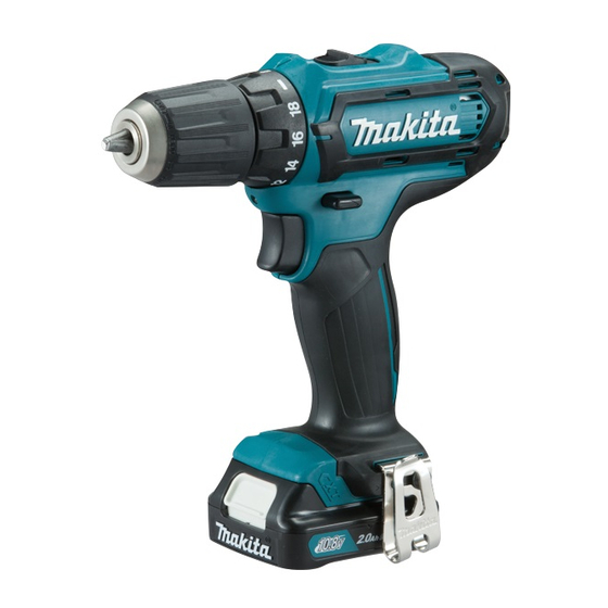
HP331D
Cordless Hammer Driver Drill
1
Model
2nd (High)
1st (Low)
2nd (High)
1st (Low)
Steel
Wood
Masonry
Hard joint
Phillips bit 2-45 (for N-type areas) or 2-50 (for M-type areas)
5
Plastic carrying case*
Charger DC10SA*
1
Charger DC10WC*
1
1
) platform. The new platform
) platform models
1
HP331D
10.8
1.5, 2.0, 4.0
17, 22, 44
Li-ion
Slide
50, 70, 130 with DC10WC
22, 30, 60 with DC10SA
170
0-1,700
0-450
0-25,500
0-6,750
0.8 (1/32) - 10 (3/8)
10 (3/8)
21 (13/16)
8 (5/16)
18 stages + drill mode
0.5 (4) - 3.5 (30)
30 (270)
14 (130)
28 (250)
Yes
Yes (2-speed)
Yes (by trigger)
Yes
Yes
1.1 (2.5)*
2
1.3 (2.9)*
3
4
Charger DC10SB*
6
Charger DC10WD*
6
OFFICIAL USE
for ASC & Sales Shop
PRODUCT
P 1/ 18
September 2015
L
W
Dimensions: mm (")
Length (L)
201 (7-7/8)
Width (W)
66 (2-5/8)
209 (8-1/4)*
Height (H)
228 (9)*
*2 With BL1015/ BL1020B
*3 With BL1040B
Driver bits
Belt clip
1
Socket bits
Bit holder
1
Holster
H
2
3
Advertisement
Table of Contents

Related Manuals for Makita HP331D


Summary of Contents for Makita HP331D
- Page 1 Li-ion battery instead of stick one; use of the new battery provides stable contact between battery and tool and the same ergonomic handle as LXT series models to obtain more satisfaction from professional users. Model HP331D is one of the first new 10.8V (12V max* ) platform models to launch.
- Page 2 October 2015 CORDLESS HAMMER DRIVER DRILL HP331D CORDLESS DRIVER DRILL DF331D CORDLESS DRIVER DRILL DF031D REPAIR MANUAL 2 / 18...
-
Page 3: Table Of Contents
About This Manual ..................................7 Repair ..................................... 7 2.1. NECESSARY REPAIRING TOOLS ............................7 2.2. DISASSEMBLY/ASSEMBLY .............................. 8 2.2.1. DRILL CHUCK (Only for HP331D, DF331D) ......................8 2.2.1.1. Disassembling ..............................8 2.2.1.2. Assembling ..............................10 2.2.2. Gear ass’y and motor section ..........................10 2.2.2.1. -
Page 4: Exploded Diagram
October 2015 EXPLODED DIAGRAM Figure 1 4 / 18... - Page 5 October 2015 Figure 2 5 / 18...
- Page 6 October 2015 Figure 3 6 / 18...
-
Page 7: About This Manual
October 2015 ABOUT THIS MANUAL The number in the parenthesis () is the item number on the exploded diagram (Figure Figure Figure REPAIR Repair the machine in accordance with “Instruction manual” or “Safety instructions”. 2.1. NECESSARY REPAIRING TOOLS Code No. Description Use for 1R003... -
Page 8: Disassembly/Assembly
October 2015 2.2. DISASSEMBLY/ASSEMBLY 2.2.1. DRILL CHUCK (ONLY FOR HP331D, DF331D) 2.2.1.1. DISASSEMBLING 1. Remove M6x22(-) Flat head screw by turning it clockwise with Impact driver. Note: M6x22(-) Flat head screw: HP331D M5x22(-) Pan head screw: DF331D Stable operation is available if you tighten claws of Drill chuck with a Round -bit in advance. - Page 9 4. Use 1R359 to remove Keyless drill chuck if it cannot be removed in the previous step. 5. The component of Gear assembly is as follows. 6. Apply a small amount of Makita grease FA No. 2 if needed. Lock...
-
Page 10: Assembling
5. If you reuse the Screw removed from Drill chuck, apply ThreeBond 1342 or Loctite 243 to the thread of the Screws. Figure 8 Note: M6x22(-) Flat head screw: HP331D M5x22(-) Pan head screw: DF331D 2.2.2. GEAR ASS’Y AND MOTOR SECTION 2.2.2.1. DISASSEMBLING It is required to remove Drill chuck when replacing Gear assembly. - Page 11 October 2015 2. Remove Gear ass'y (11), Motor (12) and Speed change (12) lever (1) from Housing L (14) at a time. (11) (14) Figure 10 3. Remove Speed change lever ass’y (1) from Gear ass'y (11). Note: Be careful not to lose Compression springs 4. Remove (11) Compression spring 4...
-
Page 12: Assembling
October 2015 2.2.2.2. ASSEMBLING 1. Set the Speed change lever ass’y of Gear ass’y (11) to High speed mode. 2. Remove Motor bracket by turning Gear ass'y (11) counterclockwise when you replace it. (11) Motor bracket Figure 14 (13) Red mark (12) Motor bracket Figure 15... -
Page 13: Bit Installation Portion Of Gear Ass'y
October 2015 6. Fit the concave portion of F/R change lever (6) to the projection of Switch (7). Concave portion of F/R change lever (6) Projection of switch (7) Figure 17 2.2.3. BIT INSTALLATION PORTION OF GEAR ASS'Y 2.2.3.1. DISASSEMBLING 1. -
Page 14: Assembling
October 2015 2.2.3.2. ASSEMBLING Assemble by reversing the disassembly procedure. 2.2.4. SPEED CHANGE LEVER ASS’Y 2.2.4.1. ASSEMBLING Assemble by reversing the disassembly procedure. Compression spring 4 (x2) 1. Assemble Compression spring 4 (x2) as drawn. Note: Hook one roll of the spring to the notches of Speed change lever. -
Page 15: Leaf Spring
October 2015 2.2.5. LEAF SPRING 2.2.5.1. ASSEMBLING 1. Assemble Leaf spring as shown. (14) Face projection inside. Leaf spring Figure 23 15 / 18... -
Page 16: Circuit Diagram
October 2015 CIRCUIT DIAGRAM Color index of lead wires' sheath DC Motor Black Red mark circuit Blue 24AWG, UL1685 White Line filter A Flag receptacles Yellow φ10-11mm w/o lock (if used) (#187, t=0.5) 16AWG 16AWG Straight receptacles With lock (#187, t=0.8) Resistor AWG22 Line filter B... -
Page 17: Repair Of Led Circuit
October 2015 3.1. REPAIR OF LED CIRCUIT Use Non-insulated connector and Polyolefin tube (inner diameter: ø4.0mm) as shown below. Figure 24. (Cut lead wires if necessary.) When repairing, put terminals in the designated position shown in Cut Lead wire in the position shown on the left. Cutting position of Red lead wire (The same surface as the root of Tab terminal)... -
Page 18: Wiring Diagram
October 2015 WIRING DIAGRAM Motor connector portion Assemble receptacles to Motor as drawn. Connector Bend motor terminal as drawn. Rib A Do not put Receptacle Red mark (with Black lead wire) Receptacle over Rib A. (with Black lead wire) Put Line filter A (if used) in this space. Gear ass’y DC Motor Pass Lead wire (Red)