Cisco Catalyst 9600 Series Hardware Installation Manual
Hide thumbs
Also See for Catalyst 9600 Series:
- Installation note (18 pages) ,
- Installation manual (34 pages) ,
- Manual (13 pages)
Table of Contents
Advertisement
Advertisement
Table of Contents

Related Manuals for Cisco Catalyst 9600 Series


Summary of Contents for Cisco Catalyst 9600 Series
- Page 1 Cisco Catalyst 9600 Series Switches Hardware Installation Guide First Published: 2019-04-15 Americas Headquarters Cisco Systems, Inc. 170 West Tasman Drive San Jose, CA 95134-1706 http://www.cisco.com Tel: 408 526-4000 800 553-NETS (6387) Fax: 408 527-0883...
-
Page 2: Table Of Contents
Site Requirements Temperature Air Flow Humidity Altitude Dust and Particles Corrosion EMI and Radio Frequency Interference Shock and Vibration Power Source Interruptions System Grounding Maintaining Safety with Electricity Preventing Electrostatic Discharge Damage Cisco Catalyst 9600 Series Switches Hardware Installation Guide... - Page 3 Removing the Fan Tray from the Rear of the Chassis Installing a Fan Tray Installing the Fan Tray from the Front Panel of the Chassis Installing the Fan Tray from the Rear of the Chassis Verifying Fan Tray Installation Cisco Catalyst 9600 Series Switches Hardware Installation Guide...
- Page 4 Supervisor Module LEDs Line Card LEDs A P P E N D I X C Accessory Kit and Shelf Kit Contents Standard Accessory Kit Contents Shelf Kit Contents 23-Inch Rack Mount Kit Contents Cisco Catalyst 9600 Series Switches Hardware Installation Guide...
-
Page 5: Product Overview
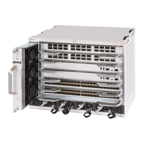
Power Supply Module Overview, on page 6 Chassis Overview The Cisco Catalyst 9606R Switch is a six-slot chassis, with two redundant supervisor module slots, four module slots, four power supply modules and a fan tray. Table 1: Cisco Catalyst 9600R Switch Features... - Page 6 Has 4 power supply slots that supports upto 4 AC/DC power supply modules. Backplane Provides 6.4Tbps bandwidth per slot. 1G is currently not supported. Figure 1: Front view of a Cisco Catalyst 9606R Chassis handholds Power switches Chassis Radio Frequency ID System ground with ground lug...
-
Page 7: Fan Tray Assembly
Fan Tray Assembly The fan tray assembly (C9606-FAN) in Cisco Catalyst 9600 Series Switches consists of a fan tray and a connector that is attached to the fan tray. It is responsible for cooling the entire chassis and interfacing with environmental monitors to trigger alarms when conditions exceed thresholds. - Page 8 The following lists the features and functionalities of a Cisco Catalyst 9600 fan tray: • Has nine individual fans (three rows of three each) and supports a minimum airflow of 720 cubic feet per minute (cfm) at 100 percent fan throttle.
-
Page 9: High Availability
To ensure high availability, the system is designed to respond to fan failures by either minimising impact or by compensating and operating at a worst case scenario specification. • If a single fan fails, the remaining fans in the row compensate with increased speed. Cisco Catalyst 9600 Series Switches Hardware Installation Guide... -
Page 10: Thresholds, Alarms, And Abnormal Acoustic Conditions
The power supplies distribute power to all slots using an internal bus-bar based power distribution mechanism. All power supply modules have internal fans and support front-to-rear airflow. The following are the supported power supply modules: Table 2: Power Supply Modules Supported on Cisco Catalyst 9600 Series Switches Part Number Description... -
Page 11: Ac Power Supply Module
Power cord connector Release latch The following are the features supported by a Cisco Catalyst 9600 Series AC power supply module: • Self-cooling, with a minimum airflow of 17 cubic feet per minute (CFM) at 100 percent load. • Supports only single-phase source AC. Source AC can be out of phase between multiple power supplies or multiple AC-power plugs on the same power supply because all AC power supply inputs are isolated. -
Page 12: Dc Power Supply Module
Figure 5: Cisco Catalyst 9600 Series 2000W DC Power Supply PSU fan Release handle Power cord connector Release latch The following are the features supported by a Cisco Catalyst 9600 Series DC power supply module: Cisco Catalyst 9600 Series Switches Hardware Installation Guide... -
Page 13: Power Supply Modes
Voltage differential between inputs is unlimited. Power Supply Modes Cisco Catalyst 9600 Series Switches offer redundant and combined configuration modes for power supplies. In both the modes, the power supplies will share the load equally. The number of power supply modules installed and the system load determine the power-level that the system expects to draw from each power supply module and consequently, the power supply mode that will be suitable. - Page 14 2000W 3940W 5880W For detailed software configuration information, see the required version of the Software Configuration Guide. In the guide, go to Contents → System Management → Environmental Monitoring and Power Management. Cisco Catalyst 9600 Series Switches Hardware Installation Guide...
-
Page 15: Preparing For Installation
Appliance and Material Safety Law prohibits the use of UL-certified cables (that have the "UL or CSA" shown on the code) for any other electrical devices than products designated by CISCO. The use of cables that are certified by Electrical Appliance and Material Safety Law (that have "PSE" shown on the code) is not limited to CISCO-designated products. - Page 16 Only trained and qualified personnel should be allowed to install, replace, or service this equipment. Statement 1030 Warning Hazardous voltage or energy is present on the backplane when the system is operating. Use caution when servicing. Statement 1034 Cisco Catalyst 9600 Series Switches Hardware Installation Guide...
- Page 17 Viewing the laser output with certain optical instruments (for example, eye loupes, magnifiers, and microscopes) within a distance of 100 mm may pose an eye hazard. Statement 1056 Cisco Catalyst 9600 Series Switches Hardware Installation Guide...
-
Page 18: Site Requirements
Observe the following guidelines: • Ensure that the system is operating in an environment that is— • 23 to 113 °F (-5 to 45 °C) up to 6000 feet (1800m) Cisco Catalyst 9600 Series Switches Hardware Installation Guide... -
Page 19: Air Flow
Note Failure to maintain adequate spacing between chassis may cause the switch chassis that is drawing in the hot exhaust air to overheat and fail. Cisco Catalyst 9600 Series Switches Hardware Installation Guide... - Page 20 Preparing for Installation Air Flow Figure 6: Air Flow Direction - Cisco Catalyst 9600 Series Switches Chassis air intake Chassis air exhaust Power supply air intake Power supply air exhaust If you are installing your switch in an enclosed or partially enclosed rack, we strongly recommend that you verify that your site meets the following guidelines: •...
-
Page 21: Humidity
The standards listed below provide guidelines for acceptable working environments and acceptable levels of suspended particulate matter: • National Electrical Manufacturers Association (NEMA) Type 1 • International Electrotechnical Commission (IEC) IP-20 Cisco Catalyst 9600 Series Switches Hardware Installation Guide... -
Page 22: Corrosion
Category 5e, Category 6, and Category 6a cables can store large levels of static electricity because of the dielectric properties of the materials used in their construction. Always ground the cables (especially in new cable runs) to a suitable and safe earth ground before connecting them to the module. Cisco Catalyst 9600 Series Switches Hardware Installation Guide... -
Page 23: Shock And Vibration
Leaving the system on may cause problems when the power is restored; all other appliances left on in the area may create large voltage spikes that may damage the system. Cisco Catalyst 9600 Series Switches Hardware Installation Guide... -
Page 24: System Grounding
Commercial building is located in an High Best grounding practices must be closely area where lightning storms occur followed. frequently, but is not prone to direct lightning strikes. Cisco Catalyst 9600 Series Switches Hardware Installation Guide... - Page 25 Category 5e, Category 6, and Category 6a cables can store large levels of static electricity because of the dielectric properties of the materials used in their construction. Always ground the cables (especially in new cable runs) to a suitable and safe earth ground before connecting them to the module. Cisco Catalyst 9600 Series Switches Hardware Installation Guide...
-
Page 26: Maintaining Safety With Electricity
• Use the correct external power source. Operate the product only from the type of power source indicated on the electrical ratings label. If you are not sure of the type of power source required, consult the Cisco Technical Assistance Center or a local electrician. -
Page 27: Preventing Electrostatic Discharge Damage
This may cause the output voltage waveform to the switch to become distorted, resulting in an undervoltage situation in the system. Cabling Requirements When running power and data cables together in overhead cable trays or subfloor cable trays, be aware of the following caution: Cisco Catalyst 9600 Series Switches Hardware Installation Guide... -
Page 28: Rack-Mounting Guidelines
We strongly recommend that power cabling runs and other potential noise sources be located as far away as practical from LAN cabling that terminates on Cisco equipment. In situations where this type of long parallel cable runs exist and cannot be separated by at least 3.3 feet (1 meter), we recommend that you shield these potential noise sources. -
Page 29: Site Preparation Checklist
Site Preparation Checklist The following table lists the site-planning activities that you should perform prior to installing the switch. Completing each activity helps ensure a successful switch installation. Cisco Catalyst 9600 Series Switches Hardware Installation Guide... - Page 30 • UPS for power failures Grounding evaluation • Circuit breaker size • CO ground (AC powered systems) Cable and interface equipment evaluation • Cable type • Connector type • Cable distance limitations • Interface equipment (transceivers) Cisco Catalyst 9600 Series Switches Hardware Installation Guide...
- Page 31 Refer to the power supply'VA rating as a sizing criteria in determining the output required by the UPS. The power supply kVA rating value is listed in the specifications table for each power supply in Appendix A (power supply specifications). Cisco Catalyst 9600 Series Switches Hardware Installation Guide...
- Page 32 Preparing for Installation Site Preparation Checklist Cisco Catalyst 9600 Series Switches Hardware Installation Guide...
-
Page 33: Installing The Switch
Do not discard the shipping container when you unpack the switch. Flatten the shipping cartons and store them with the pallet. You will require these containers if you have to move or ship the switch in the future. Cisco Catalyst 9600 Series Switches Hardware Installation Guide... -
Page 34: Install The Switch As Shipped
Figure 7: Attaching the Cable Guides Screws to attach the cable guides to the Cable guides L-brackets on the chassis Step 2 Secure the chassis to the rack rails with four screws on each side. Cisco Catalyst 9600 Series Switches Hardware Installation Guide... - Page 35 Installing the Cable Guide on the Chassis with L-Brackets Preinstalled on the Chassis Figure 8: Mounting the Chassis to the Rack Screws to attach the chassis to the rack post Cable guide installed Cable guide installation is complete. Cisco Catalyst 9600 Series Switches Hardware Installation Guide...
-
Page 36: Rack-Mounting The Chassis As Shipped
Installing the Switch Rack-Mounting the Chassis as Shipped Figure 9: Chassis with Cable Guide Attached Rack-Mounting the Chassis as Shipped This procedure shows how to rack mount the chassis as shipped. Cisco Catalyst 9600 Series Switches Hardware Installation Guide... - Page 37 Insert the rear of the chassis between the mounting posts of the rack. Step 2 Align the mounting holes in the L bracket on the switch or on the cable mount (if installed) with the mounting holes in the equipment rack. Cisco Catalyst 9600 Series Switches Hardware Installation Guide...
- Page 38 Figure 10: Securing the Chassis to the Rack Posts 10-32 or 12-24 pan head screws Cable guides Step 3 Secure the chassis to the rack with either 10-32 or 12-24 pan head screws from the chassis standard accessory kit. Cisco Catalyst 9600 Series Switches Hardware Installation Guide...
- Page 39 2. Installing and connecting the power supplies to the power source. 3. Connecting the network interface cables to the supervisor module and line card modules. This may involve installing transceivers before you attach the network interface cables. Cisco Catalyst 9600 Series Switches Hardware Installation Guide...
-
Page 40: Install The Switch With Shelf Brackets
You have ordered and received the shelf kit. Procedure Step 1 Remove and discard the L-brackets and the ten mounting screws that the chassis is shipped with. Do not re-use them during any part of the installation process. Cisco Catalyst 9600 Series Switches Hardware Installation Guide... - Page 41 Installing the Switch Installing the Shelf Kit L-Brackets Figure 12: L-Brackets the Chassis is Shipped with Left L-bracket Right L-bracket Cisco Catalyst 9600 Series Switches Hardware Installation Guide...
- Page 42 Installing the Switch Installing the Shelf Kit L-Brackets Figure 13: Removing L-Brackets the Chassis is Shipped With Mounting screws the chassis is shipped with Cisco Catalyst 9600 Series Switches Hardware Installation Guide...
- Page 43 Step 3 Using the M4 x 8 mm Phillips flat head screws in the shelf kit, secure the L-brackets to the front-left and front-right sides of the chassis (four on each side). Cisco Catalyst 9600 Series Switches Hardware Installation Guide...
-
Page 44: Installing The Shelf Brackets And The Crossbar
You have to front-mount the shelf brackets. Before you begin Determine the clearance between the insides of the left and right rails of your rack system and install the shelf brackets accordingly. Keep these tools handy: Cisco Catalyst 9600 Series Switches Hardware Installation Guide... - Page 45 Use the same type of screws for the left and right shelf bracket. Figure 16: Installing the Shelf Brackets Pan head screws from the shelf kit to secure Shelf brackets the shelf brackets to the rack posts Cisco Catalyst 9600 Series Switches Hardware Installation Guide...
-
Page 46: Installing The Cable Guide On The Chassis With Shelf Kit L-Bracket
Install the cable guide to the chassis. Two people will be required for this task. Installing the Cable Guide on the Chassis with Shelf Kit L-Bracket Procedure Step 1 Position the cable guides and align with the shelf kit L-brackets installed on the chassis. Cisco Catalyst 9600 Series Switches Hardware Installation Guide... -
Page 47: Rack-Mounting The Chassis
Two people are required to lift the chassis. To prevent injury, keep your back straight and lift with your legs, not your back. Statement 164 We recommend that you have a third person to assist in this procedure. Cisco Catalyst 9600 Series Switches Hardware Installation Guide... - Page 48 • Install the shelf kit L brackets on the chassis and the shelf brackets and crossbar on the rack posts. • Install the cable guide. Procedure Step 1 Pull out all four of the handholds on the chassis. Cisco Catalyst 9600 Series Switches Hardware Installation Guide...
- Page 49 Rest the back end of the chassis on the edges of the shelf bracket rails and slide it in until the first pair of handles on both sides of the chassis are near the rack posts. Step 4 Push in the handholds that are closest to the rack posts. Cisco Catalyst 9600 Series Switches Hardware Installation Guide...
- Page 50 Handholds closest to the rack posts, pushed Step 5 Continue sliding the chassis in until the second pair of handholds are near the rack posts. Push in the second pair of handholds. Cisco Catalyst 9600 Series Switches Hardware Installation Guide...
- Page 51 Continue sliding the chassis rests completely on the shelf brackets and the crossbar. Slide in further until the L brackets make contact with the rack posts. Step 7 Secure the chassis to the rack with either the 10-32 or 12-24 pan head screws from the chassis standard accessory kit. Cisco Catalyst 9600 Series Switches Hardware Installation Guide...
- Page 52 Installing the Switch Rack-Mounting the Chassis Figure 22: Securing the Chassis to the Rack Posts 10-32 or 12-24pan head screws Cisco Catalyst 9600 Series Switches Hardware Installation Guide...
- Page 53 What to do next After installing the chassis in its location, complete the installation process by: 1. Connecting the chassis to system ground. 2. Installing and connecting the power supplies to the power source. Cisco Catalyst 9600 Series Switches Hardware Installation Guide...
-
Page 54: Install The Switch In Nebs-Compliant Mode
Before installing the brackets on the chassis, determine whether to install the chassis from the front or the rear of the rack. Cisco Catalyst 9600 Series Switches Hardware Installation Guide... - Page 55 Figure 24: Remove the Mounting Ears Mounting screws Step 2 Install the rack ear brackets on the left and right sides of the chassis. These brackets connect the chassis to the rack. Cisco Catalyst 9600 Series Switches Hardware Installation Guide...
- Page 56 Installing the Switch Rack-Mounting the Chassis in NEBS-Compliant Mode Figure 25: Install the Rack Ear Brackets Screws to secure the rack ear Rack ear brackets brackets Step 3 Install the filter brackets. Cisco Catalyst 9600 Series Switches Hardware Installation Guide...
- Page 57 Installing the Switch Rack-Mounting the Chassis in NEBS-Compliant Mode Figure 26: Install the Filter Brackets M3x6mm flat head screws Step 4 Install the right and the left wall covers. Cisco Catalyst 9600 Series Switches Hardware Installation Guide...
- Page 58 Figure 28: Secure the Chassis to Rack 10-32 or 12-24 pan head screws Step 6 Align the air filter with the top and the bottom edges of the air filter slot. Cisco Catalyst 9600 Series Switches Hardware Installation Guide...
- Page 59 Insert the air filter into its housing with the arrows pointing toward the chassis. The arrows on the top edge of the air filter note the direction of airflow. Airflow direction is from right to left, when you stand facing the chassis. Cisco Catalyst 9600 Series Switches Hardware Installation Guide...
- Page 60 To comply with Telecordia GR-63-Core standard air filter requirements for NEBS deployments, the air filter must be replaced, not cleaned. Step 8 Install the top and base covers as shown in the illustrations: Cisco Catalyst 9600 Series Switches Hardware Installation Guide...
-
Page 61: Establishing System Ground
Establishing System Ground Figure 30: Top Cover and Base Cover 10-32 or 12-24 pan head screws Establishing System Ground To attach the grounding lug and cable to the grounding pad, perform these steps: Cisco Catalyst 9600 Series Switches Hardware Installation Guide... - Page 62 Secure the grounding lug to the system ground connector with two M4 screws. Ensure that the grounding lug and the grounding wire do not interfere with other switch hardware or rack equipment. Cisco Catalyst 9600 Series Switches Hardware Installation Guide...
- Page 63 Figure 31: Locating and Connecting System Ground M4 screws to secure the lug to the connector Grounding lug Stripped end of the grounding wire inserted into the open end of the grounding lug Cisco Catalyst 9600 Series Switches Hardware Installation Guide...
-
Page 64: Attaching An Esd Strap
If you are using the ESD wrist strap supplied with the FRUs, open the wrist strap package and unwrap the ESD wrist strap. Place the black conductive loop over your wrist and tighten the strap such that it touches your bare skin well. Cisco Catalyst 9600 Series Switches Hardware Installation Guide... -
Page 65: Verifying The Switch Chassis Installation
Do not operate the system until all cards, face plates, front covers, and rear covers are in place. Statement 1029 Cisco Catalyst 9600 Series Switches Hardware Installation Guide... - Page 66 When prestaging systems in a nonproduction environment, we recommend that you run all the diagnostic tests, including the disruptive tests, to prescreen the systems for failures, if any. Cisco Catalyst 9600 Series Switches Hardware Installation Guide...
-
Page 67: Installing The Fan Tray
Installation of the equipment must comply with local and national electrical codes. Statement 1074 Removing a Fan Tray The following sections explain the steps to remove a fan tray in a Cisco Catalyst 9600 Series switches. Cisco Catalyst 9600 Series Switches Hardware Installation Guide... -
Page 68: Information About Replacing A Fan Tray
Only trained and qualified personnel should be allowed to install, replace, or service this equipment. Statement 1030 Warning No user-serviceable parts inside. Do not open. Statement 1073 Starting in the privileged EXEC mode, enter the following command: Cisco Catalyst 9600 Series Switches Hardware Installation Guide... -
Page 69: Removing The Fan Tray From The Front Of The Chassis
Use the Phillips-head screwdriver and loosen the two captive installation screws on the front panel of the replacement fan tray (the side with the fan STATUS LED), to detach it from the connector. Cisco Catalyst 9600 Series Switches Hardware Installation Guide... - Page 70 Step 2 Proceed with removing the fan tray from the chassis. Loosen the two captive installation screws on the front panel of the fan tray (the side with the fan STATUS LED). Cisco Catalyst 9600 Series Switches Hardware Installation Guide...
-
Page 71: Removing The Fan Tray From The Rear Of The Chassis
Removing the Fan Tray from the Rear of the Chassis When you remove the fan tray from the rear, the fan tray assembly is removed. This includes the fan tray and the connector. Cisco Catalyst 9600 Series Switches Hardware Installation Guide... - Page 72 The system can safely run without a fan tray only for 2 minutes. So it is important to complete this first step before you remove the fan tray from the rear of the chassis. Cisco Catalyst 9600 Series Switches Hardware Installation Guide...
- Page 73 Figure 35: Fan Tray with the Connector Fan tray with the connector Step 2 Proceed with removing the fan tray from the chassis. Loosen the two captive installation screws on the rear panel of the fan tray. Cisco Catalyst 9600 Series Switches Hardware Installation Guide...
-
Page 74: Installing A Fan Tray
Set the removed fan tray aside and proceed with installing the replacement or spare fan tray. Installing a Fan Tray The following sections provide information about installing a fan tray in Cisco Catalyst 9600 Series switches. Cisco Catalyst 9600 Series Switches Hardware Installation Guide... -
Page 75: Installing The Fan Tray From The Front Panel Of The Chassis
Slide the fan tray into the chassis until the two captive installation screws make contact with the chassis. Step 4 Tighten the two captive installation screws on the front, to secure the fan tray assembly in the chassis. Cisco Catalyst 9600 Series Switches Hardware Installation Guide... -
Page 76: Installing The Fan Tray From The Rear Of The Chassis
STATUS LEDs) are tight. Be careful not to overtighten the screws. Step 2 Hold the fan tray assembly such that the side with the STATUS LED is inserted first. Figure 38: Inserting the Fan Tray from the Rear of the Chassis Cisco Catalyst 9600 Series Switches Hardware Installation Guide... -
Page 77: Verifying Fan Tray Installation
If after several attempts the fans do not operate, or if you experience trouble with the installation (for instance, if the captive installation screws do not align with the chassis holes), contact the Cisco TAC for assistance. Cisco Catalyst 9600 Series Switches Hardware Installation Guide... - Page 78 Installing the Fan Tray Verifying Fan Tray Installation Cisco Catalyst 9600 Series Switches Hardware Installation Guide...
-
Page 79: Installing A Power Supply Unit
• In the combined mode, the module is still hot-swappable as long as the difference between total output power and the total used power is greater than the capacity of the module being removed. Total output power – Total used > Capacity of power supply module being removed. Cisco Catalyst 9600 Series Switches Hardware Installation Guide... - Page 80 Only trained and qualified personnel should be allowed to install, replace, or service this equipment. Statement 1030 Warning Ultimate disposal of this product should be handled according to all national laws and regulations. Statement 1040 Cisco Catalyst 9600 Series Switches Hardware Installation Guide...
-
Page 81: Removing A Power Supply Module
Loosen and remove the retainer strip that is around the power cord. Step 3 Remove the power cord from the power receptacle on the power supply. Step 4 Press the release latch at the right side of the power supply module inwards. Cisco Catalyst 9600 Series Switches Hardware Installation Guide... - Page 82 Do not leave any power supply slot open for any amount of time while the system is powered up. Before inserting a new power supply unit, for instance, when replacing the unit, ensure that there are no foreign, conductive or other objects, or debris in the slot. Cisco Catalyst 9600 Series Switches Hardware Installation Guide...
-
Page 83: Installing A Power Supply Module
Slide the power supply all the way into the power supply bay. Make sure that the power supply is fully seated in the bay. When correctly installed, the latch on the power supply locks-in the module, to avoid accidental removal of the module. Cisco Catalyst 9600 Series Switches Hardware Installation Guide... - Page 84 Verify that all site power and grounding requirements have been met. Step 6 Verify that you have the correct power cord for your location and power supply rating and only then plug the power cord connector into the power supply receptacle. Cisco Catalyst 9600 Series Switches Hardware Installation Guide...
- Page 85 Depending on the width of the power cord, adjust the size of the retainer clamp, if required. c) Press the tabs on the retainer clamp towards each other to secure the power cord. Cisco Catalyst 9600 Series Switches Hardware Installation Guide...
-
Page 86: Connecting To A Power Source
Connecting to an AC Power Source To connect to a power source, follow these steps: Warning Take care when connecting units to the supply circuit so that wiring is not overloaded. Statement 1018 Cisco Catalyst 9600 Series Switches Hardware Installation Guide... -
Page 87: Connecting To A Dc Power Source
Prior to connecting the power supply to a power source, ensure that the chassis is properly grounded. Step 2 Plug the DC power cable into the DC power receptacle on the power supply module. Cisco Catalyst 9600 Series Switches Hardware Installation Guide... - Page 88 Attach the negative cables to the negative terminals of a DC power source, and attach the positive cables to the positive terminals of the same power source. Cisco Catalyst 9600 Series Switches Hardware Installation Guide...
- Page 89 When you first activate the power supply, you can verify the functionality of the LED by checking that LED turns on for a couple of seconds. If the LED is flashing amber or green, check the power connections on the power supply and the power source. Cisco Catalyst 9600 Series Switches Hardware Installation Guide...
-
Page 90: Verifying The Power Supply Installation
Removing and Installing Power Supply Blanks If a power supply bay in a chassis is unused, you must cover it with a power supply blank cover to maintain proper airflow through the chassis. (Part number C9606-PWR-BLANK=). Cisco Catalyst 9600 Series Switches Hardware Installation Guide... - Page 91 To remove the blank cover from a bay, use the release handles to hold the blank cover (with your thumb and index fingers), squeeze both the handles toward each other and slide the cover out of the bay. Cisco Catalyst 9600 Series Switches Hardware Installation Guide...
- Page 92 You can hold the blank cover by the outside edges when you perform this task; alternatively, use the release handles to hold the blank cover. Cisco Catalyst 9600 Series Switches Hardware Installation Guide...
- Page 93 Figure 49: Power Supply Blank Cover Installed Power supply blanks after installation Note Power supply blank covers can be placed in any slot when fewer than 4 power supplies are installed in a chassis. Cisco Catalyst 9600 Series Switches Hardware Installation Guide...
-
Page 94: Finding The Serial Number
Finding the Serial Number If you contact Cisco Technical Assistance, you need to know the serial number. These figures show where the serial number is located. You can also use the show version privileged EXEC command to see the serial number. -
Page 95: Appendix A Technical Specifications
• 23°F to 122°F (-5ºC to +50ºC), up to 6,000 feet (1800 m) altitude for short-term • 23°F to 122°F (-5ºC to +45ºC), up to 10,000 feet (3000 m) exceptional conditions Nonoperating and storage -40° to 167°F (-40° to 75°C) temperature Cisco Catalyst 9600 Series Switches Hardware Installation Guide... - Page 96 -24 db /octave Minimum ambient temperature for cold startup is 0ºC Short-term exceptional conditions are for no longer than a one-year period of—96 consecutive hours, or 360 hours total, or 15 occurrences. Cisco Catalyst 9600 Series Switches Hardware Installation Guide...
-
Page 97: Power Supply Specifications
Power supply output • 100 to 120 VAC operation • 12V output — 1050W • 200 to 240 VAC operation • 12V output — 2000W Output holdup time 20 ms minimum with 1200W output Cisco Catalyst 9600 Series Switches Hardware Installation Guide... -
Page 98: 2000W Dc-Input Power Supply Specifications
The operating altitude in China is 6,561.6 ft. (2000 m) maximum Note • Non-operating: -1,000 to 50,000 feet over allowable temperature range Heat dissipation (in 932 BTU per hour (maximum) British Thermal Units (BTU)) Weight 2.82 lb (1.28 kg) Cisco Catalyst 9600 Series Switches Hardware Installation Guide... -
Page 99: Chassis And Module Power And Heat Values
Line Cards AC-Input DC-Output in Current @ Current @ Current @ Current @ Heat Diss. in Power in Watts 120V 180V 240V BTU / hr. Watts (Power (Power Requested) Allocated) C9600-LC-48YL C9600-LC-24C Cisco Catalyst 9600 Series Switches Hardware Installation Guide... -
Page 100: Weight Specifications
2.82 lb (1.28 kg) Blank Covers PID (add = for spare) Weight C9606-SLOT-BLANK 2.87 lb (1.3 kg) (Cisco Catalyst 9600 Series Blank for Chassis Module Slot) C9606-PWR-BLANK 0.18 lb (0.08 kg) (Cisco Catalyst 9600 Series Blank for Chassis Power Supply Slot) -
Page 101: Leds
Power Supply Modules LEDs LED Position or Colour Meaning Solid Green Indicates that the power supply module is switched on with outputs 12V main and 12Vstandby available and in regulation. Cisco Catalyst 9600 Series Switches Hardware Installation Guide... -
Page 102: Supervisor Module Leds
Indicates a fault in the module due to parity error or failed diagnostic tests or hardware failure. Indicates that the supervisor module is disabled or is not powered up. Solid blue Identifies the supervisor module receiving the beacon signal. BLUE BEACON Cisco Catalyst 9600 Series Switches Hardware Installation Guide... -
Page 103: Line Card Leds
Port link is up and indicating packet activity. PORT LINK Amber Port link is disabled, that is, administratively down. No signal is detected, the link is down, or the port is not connected. Cisco Catalyst 9600 Series Switches Hardware Installation Guide... - Page 104 LEDs Line Card LEDs Cisco Catalyst 9600 Series Switches Hardware Installation Guide...
-
Page 105: Accessory Kit And Shelf Kit Contents
Switch Model Standard Accessory Kit Part Number Catalyst 9606R Switch C9606-ACC-KIT= Cisco Catalyst 9600 Series Switches ship with a standard accessory kit, which includes the following items: Item Quantity 12-24 x 0.75 inch M, Phillips screws 10-32 x 0.75 inch M, Phillips screws... -
Page 106: Shelf Kit Contents
The 23-inch rack mount kit is not part of the standard accessory kit. You must order it separately by using the chassis-specific part number. The 23-inch rack mount kit consists of the following items: Cisco Catalyst 9600 Series Switches Hardware Installation Guide... - Page 107 Accessory Kit and Shelf Kit Contents Accessory Kit and Shelf Kit Contents Table 15: Contents of 23-Inch Rack Mount Kit Parts Description Quantity Rack Mounts M4 Phillips pan-head screws 12-24 x 3/4-inch Phillips binder-head screws Cisco Catalyst 9600 Series Switches Hardware Installation Guide...
- Page 108 Accessory Kit and Shelf Kit Contents Accessory Kit and Shelf Kit Contents Cisco Catalyst 9600 Series Switches Hardware Installation Guide...
- Page 109 Cisco has more than 200 offices worldwide. Addresses and phone numbers are listed on the Cisco website at www.cisco.com/go/offices. Cisco and the Cisco logo are trademarks or registered trademarks of Cisco and/or its affiliates in the U.S. and other countries. To view a list of Cisco trademarks, go to this URL: www.cisco.com...